

OpenEye CM-N217R User Manual
690TVL IR
Indoor Mini Dome Camera
Camera Installation & Conguration
Model no: CM-N217R
Please carefully read these instructions before using this product.
Save this document for future use.
31375AA
Regulatory Compliance
Emissions FCC part 15, subpart B, Class A
CE: EN61000-6-4:2007
Immunity CE: EN60130-4:1995 + A1:1998 + A2:2003
FCC COMPLIANCE
This product has been tested and found to comply with the limits for a Class A
digital device pursuant to Part 15 of the FCC rules. These limits are designed to
provide reasonable protection against harmful interference when the equipment
is operated in a commercial environment. The product generates, uses, and can
radiate radio frequency energy, and, if not installed and used in accordance with
the manufacturer’s instruction manual, may cause harmful interference with radio
communications. Operation of this product in a residential area is likely to cause
harmful interference, in which case you will be required to correct the interference
at your own expense.
This device complies with Part 15 of the FCC Rules. Operation is subject to the
following two conditions:
1. This device may not cause harmful interference.
2. This device must accept any interference received, including interference
that may cause undesired operation.
These limits are designed to provide reasonable protection against harmful
interference in a non-residential installation. However, there is no guarantee that
interference will not occur in a particular installation. If this equipment does cause
harmful interference with the radio or television reception, which can be determined by turning the equipment off and on, you are encouraged to try to correct
the interference by one or more of the following measures:
1. Reorient or relocate the antenna of the radio/television receiver.
2. Increase the separation between this equipment and the radio/television
receiver.
3. Plug the equipment into a different outlet so that the equipment and the
radio/television receiver are on different power mains branch circuits.
4. Consult the dealer or an experienced radio/television technician for
additional suggestions.
General Specications
Model No. CM-N217R
Image Sensor 1/3” Pixim CCD
Type / Format NTSC
Wide Dynamic Range Yes
Minimum Illumination 0.1 Lux @ 50 IRE; 0.06 Lux @ 30 IRE;
Day / Night True Day / Night (IR Cut Filter)
Resolution 690 TVL
Service Monitor Jack Yes
S/N Ratio >52dB
Focal Length 2.8 ~ 12 mm
Iris Control Auto-Iris
Synchronization Internal / Line Lock
Video Output 1.0Vpp 75Ω BNC Unbalanced
White Balance AWB, ATW
Auto White Balance Range 2200K ~ 11000K
Backlight Compensation BLC, HLC, Off
Auto Gain Control Low, Mid, High, Off
Operating Temperature 14˚ ~ 122˚ F (-10˚ ~ 50˚C)
Heater No
Power Consumption 6.12W
Rated Amperage 0.51A (24vAC)
Input Voltage 12vDC / 24vAC
Weight 0.8 lbs (0.36 kg)
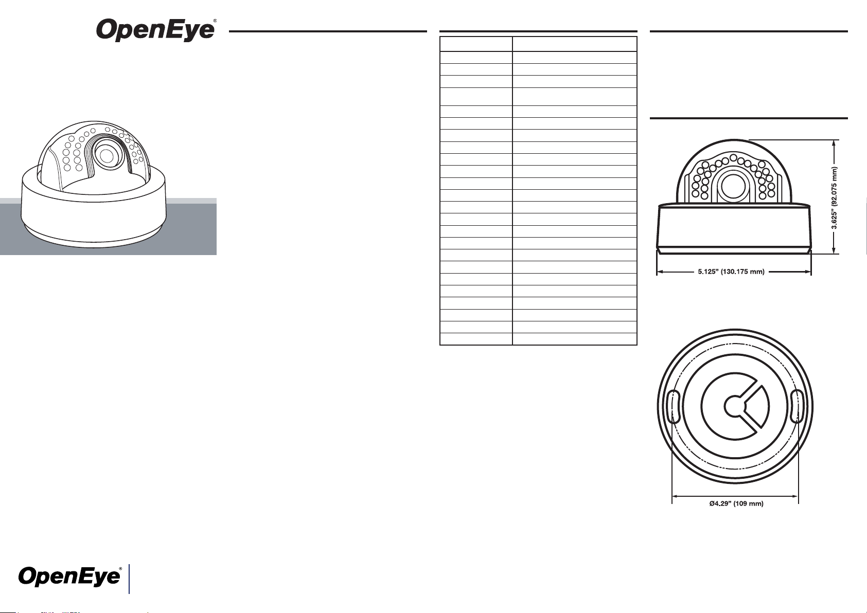
Dimensions Dome : ø5.125” (130.2 mm) x H: 3.625” (92.1 mm)
Housing / Dome Cover White / Clear
0.00 (IR LEDs engaged)
Box Contents
• Screws (x 2)
• BNC service monitor cable
Dimensions
23221 E Knox Ave
Liberty Lake, WA 99019
1.888.542.1103
www.openeye.net
Precaution
• Do not attempt to dismantle the camera module mounted
within the dome. There are no user serviceable parts in
the camera module. Refer servicing to a qualied professional.
• Handle the camera with care. Do not abuse the camera.
Avoid striking or shaking it. Improper handling and storage could damage the camera.
• Do not operate the camera beyond its temperature or
power source rating. Refer to the environmental information provided in this document.
Features
• 690 TV-Line Resolution
• Digital Noise Reduction
• 3-axis camera
• Digital Wide Dynamic Range
• True Day/Night
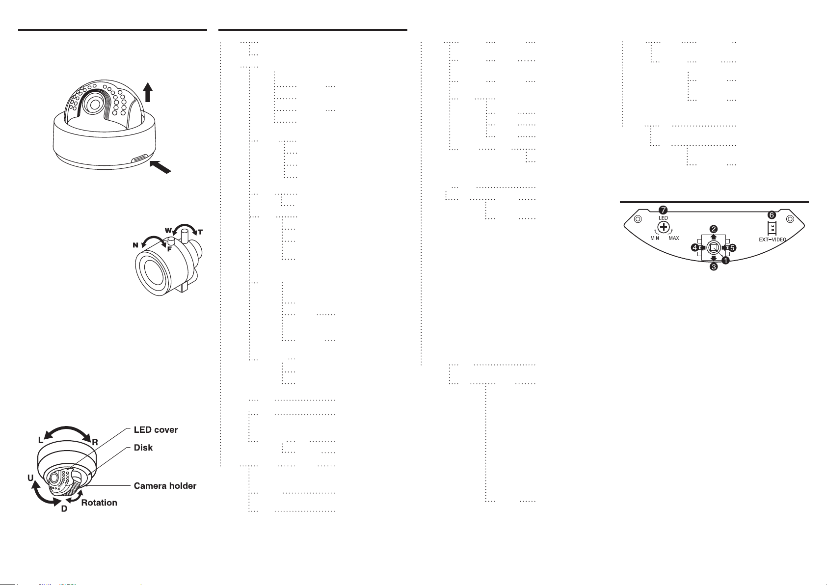
Installation
Opening the Dome
1. Push the latch button.
2. Lift the dome.
Camera Installation
1. Use the supplied screws to mount the camera on a wall
or ceiling.
2. If your camera uses a varifocal lense, adjust the lens
by opening the LED cover.
Turn the Tele-Wide knob to
adjust the eld of view. Turn
the Near-Far knob to set the
focus.
3. Once the camera is mounted
to the desired surface and is
focused correctly, re-assemble
the camera housing.
Adjusting the Camera Angle
1. To adjust the pan, the camera xture left or right within a
range of -160º ~ 190º.
2. To adjust the tilt, grasp the LED cover and adjust the
direction up or down within a range of 6º ~ 90º.
3. To adjust the vertical orientation, rotate the camera
holder within a range of -178º ~ 178º.
Camera OSD Menu
LENS
SELECT
EXPOSURE
WHITE
BALANCE
DAY &
NIGHT
MANUAL
DC
PRESETS *Preset mode for common application to
WDR LOW WDR allows you to
BLC OFF
AGC CUSTOM
SENSE-UPEnable the SENSE-UP function and
FLICKERLESS
ATW Automatic White Balance
AWC Find optimal white bal-
MANUAL R/B Adjust red or blue levels
AUTO INPUT
COLOR Image is always dis-
B/W Image is always dis-
speed up installation
CUSTOM User setting value
INDOOR
WINDOW Maximizing WDR function
OUT-
DOOR
NORMAL
MEDIUM
HIGH
ON
LOW (24)
MEDIUM
(30)
HIGH (36)
select level
OFF
AUTO For use in low light
MANUAL Select between 2X and
OFF Optimized mode fro
CRR
CRR2
KELVIN Adjust color temp.
DELAY
clearly view a subject,
even when there is a
bright light behind it.
situations, between 2X
and 64X)
64X
icker. If CRR is selected,
AWC mode will not be
available in the White
Balance menu.
ance with use of white
paper in eld of view.
The camera automatically
detects light levels and
sets mode accordingly.
played in color
played in black and white
IMAGE
ADJUST
MOTION** OFF No motion detection
PRIVACY OFF No privacy mask function
GAMMA 25 ~ 45 ~
SHARP-
NESS
COLOR
GAIN
FLIP OFF
ZOOM ON Max 4X Zoom
ON AREA
ON MASK
100
MIN ~
MAX
-8 ~ 0 ~ 8 Default: 0
HORZ Horizontal ip
VERT Vertical ip
BOTH Horizontal and vertical ip
SELECT
AREA
1 ~ 4
1-12
MASK
COLOR
Default: 45
Default: MAX
PAN, TILT: Zoomed
image can be moved
horizontally and vertically
Select up to 4 motion
detection areas
• Adjust position and
size of motion detec-
tion area
• Press ENTER to
move the motion
area setting section.
Press ENTER again
to change the mask
color
• When mask is white,
you can move the
mask up, down, left,
and right
• When the mask is
green and red, you
can adjust the mask
size
• Press ENTER for
a few seconds to
escape
• Congure up to 12
privacy masks
• Press SET to open
privacy mask settings.
Press SET again to
change the mask
color
• When mask is white,
black, or red, it can be
moved up, down, left,
and right
• When mask is blue,
you can adjust the
size
• Press SET for a few
seconds to escape
Select the mask
color (WHITE, RED, OR
BLACK)
FUNC-
TION
SETUP
SYNC INT Internal sync with 12V
RS-485
SETUP**
CAMERA
ID SETUP
LL External sync with 24V
CAMERA # ID setting for RS-485
ID DISPLAY
CAMERA IDChange the camera ID
ID
POSITION
V-PHASE Phase controllable at
communication (1 ~ 256)
Display the camera ID on
the screen
Select the position to
display the ID on the
screen
Power
AC power
24V AC
Function Setting
1. Push the lever to access the menu and conrm selection. Push the lever for one second to open or close the
menu. Use the lever to return to the previous menu from
motion detection or privacy mask setting sections.
2. Push the lever up to move the cursor up.
3. Push the lever down to move the cursor down.
4. Push the lever left to move the cursor left.
5. Push the lever right to move the cursor right.
6. Plug a test monitor into the optional EXT-VIDEO terminal to view menu screens during installation.
7. Adjust the LED light level with the screw.
**MOTION and RS-485 SETUP
are not supported by OpenEye
 Loading...