

OpenEye CM-N207, CM-N207R Installation/configuration Manual

650TVL IR
Indoor Mini Dome Camera
Model no: CM-N207
CM-N207R
Camera Installation & Conguration
Please carefully read these instructions before using this product.
Save this document for future use.
31374AA
23221 E Knox Ave
Liberty Lake, WA 99019
1.888.542.1103
www.openeye.net
Precaution
• Do not attempt to dismantle the camera module mounted
within the dome. There are no user serviceable parts in
the camera module. Refer servicing to a qualied professional.
• Handle the camera with care. Do not abuse the camera.
Avoid striking or shaking it. Improper handling and storage could damage the camera.
• Do not operate the camera beyond its temperature or
power source rating. Refer to the environmental information provided in this document.
Features
• 650 TV-Line Resolution
• Digital Noise Reduction
• 3-axis camera
• Digital Wide Dynamic Range
• True Day/Night
General Specications
Model No. CM-N207 CM-N207R
Image Sensor 1/3” Sony CCD
Type / Format NTSC
Wide Dynamic Range Yes, Digital WDR
Minimum Illumination 0.05 Lux @ 50 IRE;
0.01 Lux @ 30 IRE
0.05 Lux @ 50 IRE;
0.01 Lux @ 30 IRE;
0.00 Lux (IR LEDs on)
Day / Night True Day / Night (IR Cut Filter)
Resolution 650 TVL
Service Monitor Jack Yes
S/N Ratio >50dB
Focal Length 2.8 ~ 12 mm
Iris Control Auto-Iris
Synchronization Internal
Video Output 1.0Vpp 75Ω BNC Unbalanced
White Balance AWB, ATW
Auto White Balance Range 2500K ~ 9500K (ATW)
Backlight Compensation BLC, HLC, Off
Auto Gain Control Low, Mid, High, Off
Operating Temperature 14˚ ~ 122˚ F (-10˚ ~ 50˚C)
Heater No
Power Consumption 4.32W (24V AC)
2.16W (12V DC)
10.8W (24V AC)
5.4W (12V DC)
Rated Amperage 0.24A 0.45A
Input Voltage 12vDC / 24vAC
Weight 0.8 lbs (0.36 kg)
Dimensions Dome : ø5.125” (130.2 mm) x H: 3.625” (92.1 mm)
Housing / Dome Cover White / Clear
Box Contents
• Screws (x 2)
• BNC service monitor cable
Regulatory Compliance
Emissions FCC part 15, subpart B, Class A
CE: EN61000-6-4:2007
Immunity CE: EN60130-4:1995 + A1:1998 + A2:2003
FCC COMPLIANCE
This product has been tested and found to comply with the limits for a Class A
digital device pursuant to Part 15 of the FCC rules. These limits are designed to
provide reasonable protection against harmful interference when the equipment
is operated in a commercial environment. The product generates, uses, and can
radiate radio frequency energy, and, if not installed and used in accordance with
the manufacturer’s instruction manual, may cause harmful interference with radio
communications. Operation of this product in a residential area is likely to cause
harmful interference, in which case you will be required to correct the interference
at your own expense.
This device complies with Part 15 of the FCC Rules. Operation is subject to the
following two conditions:
1. This device may not cause harmful interference.
2. This device must accept any interference received, including interference
that may cause undesired operation.
These limits are designed to provide reasonable protection against harmful
interference in a non-residential installation. However, there is no guarantee that
interference will not occur in a particular installation. If this equipment does cause
harmful interference with the radio or television reception, which can be determined by turning the equipment off and on, you are encouraged to try to correct
the interference by one or more of the following measures:
1. Reorient or relocate the antenna of the radio/television receiver.
2. Increase the separation between this equipment and the radio/television
receiver.
3. Plug the equipment into a different outlet so that the equipment and the
radio/television receiver are on different power mains branch circuits.
4. Consult the dealer or an experienced radio/television technician for
additional suggestions.
Dimensions
Camera OSD Menu
EXPOSURE
LENS
SELECT
MANUAL BRIGHTNESS 0 ~ 99
E. SHUTTER AUTO, 1/60 ~
1/100000
DC BRIGHTNESS 0 ~ 99
E. SHUTTER AUTO, 1/60 ~
1/100000
AGC OFF, LOW, MIDDLE, HIGH Auto Day/Night is
disabled if AGC is
OFF
SENSE-UPAUTO, OFF, X2, X4, X8, X16,
X32, X64, X128, X256, X512,
X1024
Use sense-up in low
light environments
BACK-
LIGHT
BLC BLC LEVEL OFF, LOW, MID,
HIGH
TOP 0 ~ 15:
BOTTOM 0 ~ 16
LEFT 0 ~ 15
RIGHT 0 ~ 16
HLC HBLC OFF
MANUAL HBLC LEVEL:
OFF,LOW, MID, HIGH
TOP, BOTTOM, LEFT, RIGHT
same as BLC
MODE ALL DAY, NIGHT
HLC LEVEL 1 ~ 100
Function Setting
1. Push the lever to access the menu and conrm selection. Push the lever for one second to open or close the
menu. Use the lever to return to the previous menu from
motion detection or privacy mask setting sections.
2. Push the lever up to move the cursor up.
3. Push the lever down to move the cursor down.
4. Push the lever left to move the cursor left.
5. Push the lever right to move the cursor right.
6. Plug a test monitor into the optional EXT-VIDEO terminal to view menu screens during installation.
7. Use the debug port to upgrade your camera and for
after-sales services.
MASK 1-4 ON
TOP: 0 ~ 33
BOTTOM: 1 ~ 34
LEFT: 0 ~ 44
RIGHT 1 ~ 45
OFF: HLC MASK
OFF
D-WDR SET LEVEL 0 ~ 20
3D-DNR OFF, LOW, MID, HIGH, AUTO Reduce noise in low
light environments
WHITE BALANCE
AWB
MODE
ATW Color temp. 2500 ~ 9500 K
MANUAL M-WR 0 ~ 128: Adjust the
red value
M-WB 0 ~ 128: Adjust the
blue value
PUSH Optimize white balance for current condi-
tions
R-Y GAIN 0 ~ 255 Adjust red tone of image
B-Y GAIN 0 ~ 255 Adjust blue tone of image
DAY & NIGHT
D&N
MODE
AUTO DAY-NIGHT 7 ~ 30
NIGHT-DAY 6 ~ 29
DELAY TIME 0 ~ 15: Set the
duration
AUTO-
CDS
A. DAY-NIGHT 6 ~ 36
A. NIGHT-DAY 6 ~ 36
C. DAY-NIGHT 0 ~ 255
C. NIGHT-DAY 0 ~ 255
COLOR Fixed at Color
B&W Fixed at B&W
EXT DELAY TIME 0 ~ 15
BURST ON, OFF Enable/disable burst
signal in BW mode
C-SUP 0 ~ 100 Color suppress
control
A-SUP 0 ~ 100 Iris suppress control
SMART IRON, OFF Decreases screen
saturation of objects
within a short range
MIRROR MIRROR, OFF Vertical image
inversion
SHARP-
NESS
0 ~ 30
GAMMA 0.45, 0.55, 0.65
USER GAMMA .20 ~ 1.00 by incre-
ments of .05
PRIVACY
MASK
1 ~ 8
OFF
ON DOT SEL L_TOP, L_BOT,
R_BOT, R_TOP:
Determines location
for Motion Detection
DOT XY ENTER SETTING:
Determines coordinates
MOVE XY ENTER SETTING:
Determines coordinates
COLOR Select mask color
SPECIAL
LANGUAGE Select language (9
available)
TITLE OFF-ON EDIT Display the camera
name on screen
RESET Camera name reset
POSITION Camera name
position
DPC OFF Deactivates Detect
Pixel Correction in
low illumination
AUTO WHITE THR 0 ~ 255: Set the
limited value of white
pixel correction
LUMA THR 0 ~ 255: Set the
limited value of white
pixel correction
RETURN Move back to previ-
ous menu
FACTORY SET YES, NO Reset your camera
to factory default
conditon
EXIT
SAVE AND EXIT Save the value and
exit the menu
EXIT Escape the menu
without saving
Camera Installation
1. Use the supplied screws to mount the camera on a wall
or ceiling.
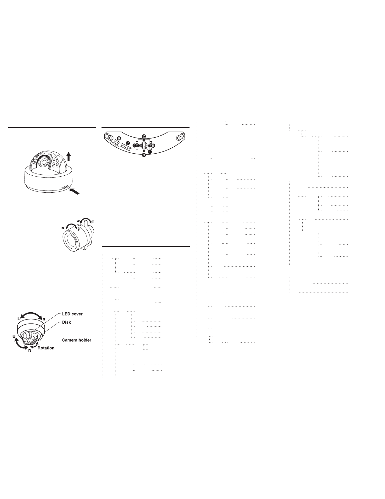
Adjusting the Camera Angle
1. To adjust the pan, the camera xture left or right within a
range of -160º ~ 190º.
2. To adjust the tilt, grasp the LED cover and adjust the
direction up or down within a range of 6º ~ 90º.
3. To adjust the vertical orientation, rotate the camera
holder within a range of -178º ~ 178º.
2. If your camera uses a varifocal lense, adjust the lens
by opening the LED cover.
Turn the Tele-Wide knob to
adjust the eld of view. Turn
the Near-Far knob to set the
focus.
3. Once the camera is mounted
to the desired surface and is
focused correctly, re-assemble
the camera housing.
Installation
Opening the Dome
1. Push the latch button.
2. Lift the dome.
 Loading...