

OpenEye CM-L812, CA-510G, CA-510W, CA-510C, CA-510P25 User Manual
...
Accessories
CA-510G
CA-510W
CA-510C
CA-510P25
CA-510P50
CA-510PML
CA-510PMS
CA-510PA25
CA-510PA50
Camera
CM-L812
www.openeye.net
36x Outdoor IP PTZ Dome
User Manual

2

31648AB 3
36x Outdoor IP PTZ Camera (CM-L812)
User Manual
Manual Edition 31648AB – JULY 2013
©2013, OPENEYE
All Ri ghts Reserved.
No part of this documentation may be reproduced in any means, electronic or mechanical, for
any purpose, except as expressed in the Software License Agreement. OpenEye shall not be
liable for technical or editorial er rors or omissi ons co ntai ned herein. The information in this
document is subject to change without notice.
The information in this publication is provided “as is” without warranty of any kind. The entire
risk arising out of the use of this information remains with recipient. In no event shall
OPENEYE be liable for any direct, consequential, incidental, special, punitive, or other
damages whatsoever (including without limitation, damages for loss of business profits,
business interruption or loss of business information), even if OPENEYE has been advised of
the possibility of such damages and whether in an action or contract or tort, including
negligence.
This documentation is copyrighted. All other rights are reserved to OPENEYE. OPENEYE,
and OpenEye, are registered trademarks of OPENEYE in the United States and elsewhere;
Windows, and Windows XP Embedded are registered trademarks of Microsoft Corporation.
All other brand and product names are trademarks or registered trademarks of the respective
owners.
OPENEYE
Liberty Lake, WA ● U.S.A.

4
Important Safeguards
1. Read Instructions
Read all of the safety and operating instructions before using the product.
2. Retain Instructions
Save these instructions for future reference.
3. Attachments / Accessories
Do not use attachments or accessories unless recommended by the
appliance manufacturer as they may cause hazards, damage product and
void warranty.
4. Installation
Do not place or mount this product in or on an unst abl e or improperly
supported location. Improperly installed product may fall, cau sing seriou s
injury to a child or adult, and damage to the product. Use only with a
mounting device recommended by the manufacturer, or sold with the
product. To insure proper mounting, follow the manufacturer's instructions
and use only mounting ac ces s ories recommended by manuf acturer.
5. Power source
This product should be operated only from the type of power source
indicated on the marking label.
Precautions
Operating
• Before using, make sure power supply and others are proper l y
connected.
• While operating, if any abnormal condition or malfunction is observed,
stop using the camera immediately and then contact your local dealer.
Handling
• Do not disassemble or tamper with parts inside the camera.
• Do not drop or subject the camera to shock and vibration as this can
damage camera.
• Do not block the cooling holes on the bracket. This camera has a
cooling fan inside the housing. Blocking the cooling holes will cause
heat to build up and cause malfunction.
• Care must be taken when you clean the clear dome cover. Scratches
and dust will ruin the image quality of your camera. Do not use strong
or abrasive detergents when cleaning the camera body. Use a dry
cloth to clean the camera when it is dirty. In case the dirt is hard to
remove, use a mild detergent and wipe the camera gently.

31648AB 5
Installation and Storage
• Install electricity w irin g carefully. Please note that input electricity to the
unit is at tolerance of DC 12V/AC 24V ± 10%. The camera is capable
of surge protection; ensure AC power model unit is grounded
appropriately against damage by heavy current or electric shock.
• Do not install the camera in areas of extreme temperatures in excess
of the allowable range. (-50°C ~50°C / -58°F ~ 122°F)
• Avoid installing in humid or dusty places. The relative humidity must
be below 90%.
• Avoid installing in places where radiation is present .
• Avoid installing in places where there are strong magnetic fields and
electric signals.
• Avoid installing in places where the camera would be subject to strong
vibrations.
• Never face the camera toward the sun. Do not aim at bright objects.
Whether the cam era is in use or not, never aim it at the sun or other
extremely bright objects. Otherwise the camera may be smeared and
damaged.
Regulation
This device complies with Part 15 of the FCC Rules. Operation is
subject to the following two conditions: (1) this device may not
cause harmful interference, and (2) this device must accept any
interference received, including interference that may cause
undesired operation.
This symbol on the product or on its packaging indicates that this
product shall not be treated as household waste in accordance with
Directive 2002/96/EC. Instead it shall be handed over to the
applicable collection point for the recycling of electrical and
electronic equipment. By proper waste handling of this product you
ensure that it has no negative consequenc es for t he env iron ment
and human health, which could otherwise be caused if this product
is thrown into the garbage bin. The recycling of materials will help to
conserve natural resources.
For more details information about recycling of th is prod uct, please
contact your local city office, your household waste disposal service
or the shop where you purchased the product.
Compliance is evidenced by written declaration from our suppliers, assuring that any
potential trace contamination levels of restricted substances are below the maximum
level set by EU Directive 2002/95/EC, or are exempted due to their application.
6
Warning
DANGEROUS HIGH VOLTAGES ARE PRESENT INSIDE THE ENCLOSURE.
DO NOT OPEN THE CABINET.
REFER SERVICING TO QUALIFIED PERSONNEL ONLY.
Caution
CAUTION: TO REDUCE THE RISK OF ELECTRIC SHOCK,
DO NOT REMOVE C O VER (OR BACK).
NO USER-SERVICEABLE PARTS INSIDE.
REFER SERVI CI NG T O QUA LIF IED SERVICE PERSONNE L.
CAUTION
RISK OF ELECTRIC SHOCK
DO NOT OPEN

31648AB 7
Standard Warranty
OpenEye warrants all new products to be free from defects in workmanship and
material under normal use for a period of two years after the date of purchase. Any
defective product that falls under this warranty will, at OpenEye's discretion, be
repaired or replaced at no additional charge. OpenEye may elect to replace defective
products with new or factory reconditioned products of equal or greater value.
Repairs made necessary by reason of misuse, alteration, normal wear, or accident
are not covered under this warranty.
Exceptions to this are listed below:
• Three Years on all Digital Recorders
• Three years on all fixed cameras
All products shall be covered by a one year advance replacement warranty*.
OpenEye will warrant all otherwise out of warranty replacement parts and repairs for
90 days from the date of OpenEye shipment.
The above warranty is the sole warranty made by OpenEye and is in lieu of all other
warranties by OpenEye express and implied, including without limitation the
warranties of merchantability and fitness for a particular purpose. Under no
circumstances will OpenEye be liable for any consequential, incidental, special or
exemplary damages arising out of or connected with the sale, delivery, use or
performance of the product, even if OpenEye is apprised of the likelihood of such
damages occurring. In no event shall OpenEye liability exceed the purchase price of
the product.
This warranty gives you specific legal rights and you may also have other rights
which vary from state to state or country to country.
*Requires corresponding security deposit. Advanced Replacement limited to
components only outside of the USA and Canada.
For the most up to date information visit www.openeye.net

8
Table of Contents
Introduction .................................................................................................................................. 11
Overview ................................................................................................................................... 11
Product Featur es ................................................................................................................. 11
Getting Started ............................................................................................................................. 12
Camera Contents ...................................................................................................................... 12
Dome Setup and Cabl e C Onnection ......................................................................................... 13
Preparations for Dome Setup ............................................................................................... 13
Dome Camera Setup ........................................................................................................... 16
Switch Defi nition ............................................................................................................. 16
Dome Cable Defi nition and Requirements ........................................................................... 17
Cable Requirements ....................................................................................................... 17
Power Connection ........................................................................................................... 18
Grounding Recom mendation .......................................................................................... 18
Ethernet Cabl e C onnection ............................................................................................. 18
12-Pin Alarm Input/Output Conn ection ............................................................................ 19
Audio Input/O utput Connection ....................................................................................... 19
Dome Installation ......................................................................................................................... 20
Overview ................................................................................................................................... 20
Dome Dimensions .................................................................................................................... 20
Optional Accessories ................................................................................................................ 21
Dome Camera Accessories.................................................................................................. 21
Mounting Accessories .......................................................................................................... 21
Ceiling Mounting with Pole ................................................................................................... 22
Wall Mounting with Wall Mount Bracket ............................................................................... 23
Wall Mounting with Corner Mount ........................................................................................ 25
Pole Mounting ...................................................................................................................... 26
Locate Camera ............................................................................................................................. 27
OpenEye Networ k Camera manager ........................................................................................ 27
Installation ............................................................................................................................ 27
Starting Netw ork Camera Manager ...................................................................................... 27
Device Addressing ............................................................................................................... 28
Finding Network Devices ................................................................................................ 28
Setup & Configuration ................................................................................................................. 29
Connecting t o the Camera ........................................................................................................ 29
Administr ator/User Privileges ............................................................................................... 29
Connecting a Stream ........................................................................................................... 30
Connecting Over the Internet ............................................................................................... 31

31648AB 9
Viewer Software ........................................................................................................................ 32
Viewer Tabs ......................................................................................................................... 32
Home ................................................................................................................................... 33
System ................................................................................................................................. 36
System ............................................................................................................................ 36
Security ........................................................................................................................... 38
Admin Passwor d ........................................................................................................ 38
Add User .................................................................................................................... 39
Delete User ................................................................................................................ 39
Edit User .................................................................................................................... 39
Network........................................................................................................................... 40
Get IP address automatically (DHCP) ........................................................................ 40
Use Fixed IP Address ................................................................................................ 40
QoS (Quality of S ervice) ............................................................................................ 42
SNMP ........................................................................................................................ 42
UPnP (Universal Plug and Play) ................................................................................ 43
DDNS ............................................................................................................................. 44
Mail ................................................................................................................................. 45
FTP ................................................................................................................................. 46
HTTP .............................................................................................................................. 47
Application ...................................................................................................................... 48
Alarm Pin Selection ......................................................................................................... 49
Alarm Pin Status Settings ............................................................................................... 50
Motion Detection ............................................................................................................. 52
Storage Managem ent ..................................................................................................... 55
Recording ....................................................................................................................... 57
Activating M icro SD/SDHC Car d R ecording ............................................................... 57
Snapshot ......................................................................................................................... 58
Information ...................................................................................................................... 59
System Log ................................................................................................................ 59
View User Information ..................................................................................................... 60
View User Privilege .................................................................................................... 60
Parameter List ................................................................................................................ 61
Software Upgrade ........................................................................................................... 62
Upgrading the Camera Viewer Software .................................................................... 62
Maintenance ................................................................................................................... 63
Video and Audio Streaming Settings .................................................................................... 64
Video Format .................................................................................................................. 64
Video Resolution ........................................................................................................ 65
Text Overlay Settings ................................................................................................. 65
Video Rotate Type ..................................................................................................... 66
GOP Settings ............................................................................................................. 66
H.264 Profile .............................................................................................................. 66
Video Compression ......................................................................................................... 67

10
Video OCX Protocol ............................................................................................................. 68
Multicast M ode ........................................................................................................... 68
Frame Rate Cont rol ........................................................................................................ 69
Audio .............................................................................................................................. 70
Transmission Mode.................................................................................................... 70
Server Gain Sett ings .................................................................................................. 70
Bit Rate ...................................................................................................................... 71
PTZ Settings ............................................................................................................................. 72
Preset .................................................................................................................................. 72
Preset Sett ing ................................................................................................................. 72
Preset Go ........................................................................................................................ 73
Pattern ................................................................................................................................. 73
Pattern Setting ................................................................................................................ 73
Pattern Run ..................................................................................................................... 74
Auto Scan ............................................................................................................................ 74
Auto Scan Setti ng ........................................................................................................... 75
Auto Scan Run ................................................................................................................ 75
Tour ..................................................................................................................................... 76
Tour Set .......................................................................................................................... 77
Tour Run ......................................................................................................................... 77
Home ................................................................................................................................... 78
Home Settings ................................................................................................................ 78
Tilt Range ............................................................................................................................ 79
Privacy Mask Settings .......................................................................................................... 80
Mask Setting ................................................................................................................... 81
Mask Clearing ................................................................................................................. 81
Camera — Exposure ............................................................................................................ 82
Camera — White Balance .................................................................................................... 83
Camera — Misc1 ................................................................................................................. 85
Camera — Misc2 ................................................................................................................. 87
Camera — Default ............................................................................................................... 88
Logout ....................................................................................................................................... 88
Specifications............................................................................................................................... 89
Camera Specifications .............................................................................................................. 89
PTZ Specifications .................................................................................................................... 90
IP Specifications ....................................................................................................................... 90

31648AB 11
INTRODUCTION
OVERVIEW
With an IP66 rating, the CM-L812 Outdoor PTZ IP Camera is suitable for outdoor
installations. The CM-L812 IP camera can transmit video at H.264 and MJPEG,
dual streaming both codecs at D1 at 30IPS. The camera’s IR cut filter and wide
dynamic rage imaging make it perfect for installations with difficult lighting
conditions. The CM-L812 has an IP66 outdoor rating and integrated heater
making the CM-L812 ideal for rugged outdoor installations with temperature as
low as -40°F (-40°C)
Product Featur e s
• 36x Optical Zoom
• Simultaneous dual streams: H.264 and MJPEG
• D1 Real-time Resolution
• 3D de-interlaced video image
• Two-way audio support
• Removable IR Cut Filter
• Wide D y namic Range (WDR)
• 3D Noise Reduction
12
GETTING STARTED
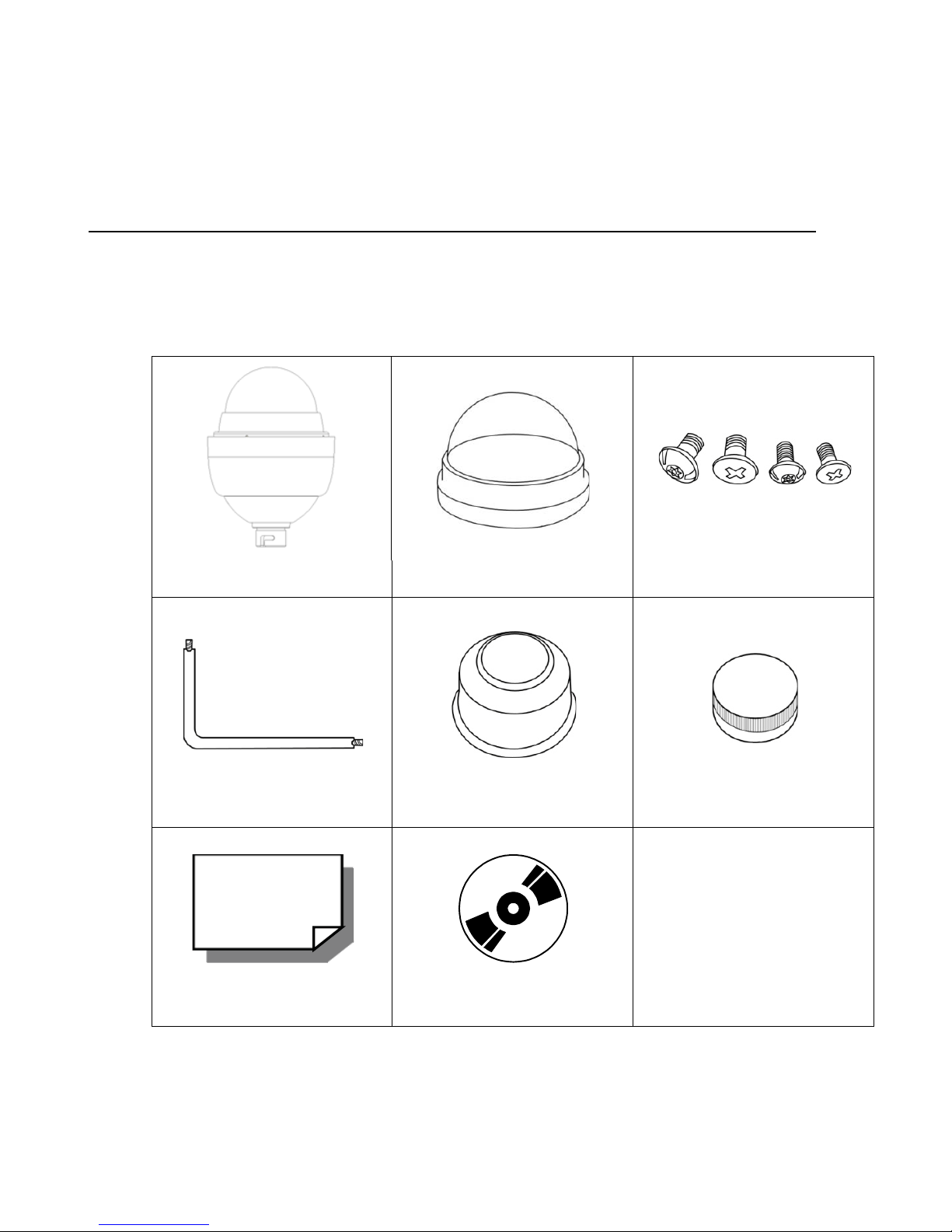
CAMERA CONTENTS
Before proceeding, please ch e ck that the box contains the items listed here. If
any item is missing or has defects, DO NOT install or oper at e the prod uct and
contact your dealer for assistance.
Dome Body Optical Cover Screws
Security Torx Tool Waterproof Gasket Lubricant
Quick Start Guide CD
31648AB 13
DOME SETUP AND CABLE CONNECTION
Before installing or connecting the dome camera, please refer to this section and
complete preparations for dome setup and all switch setti ngs.
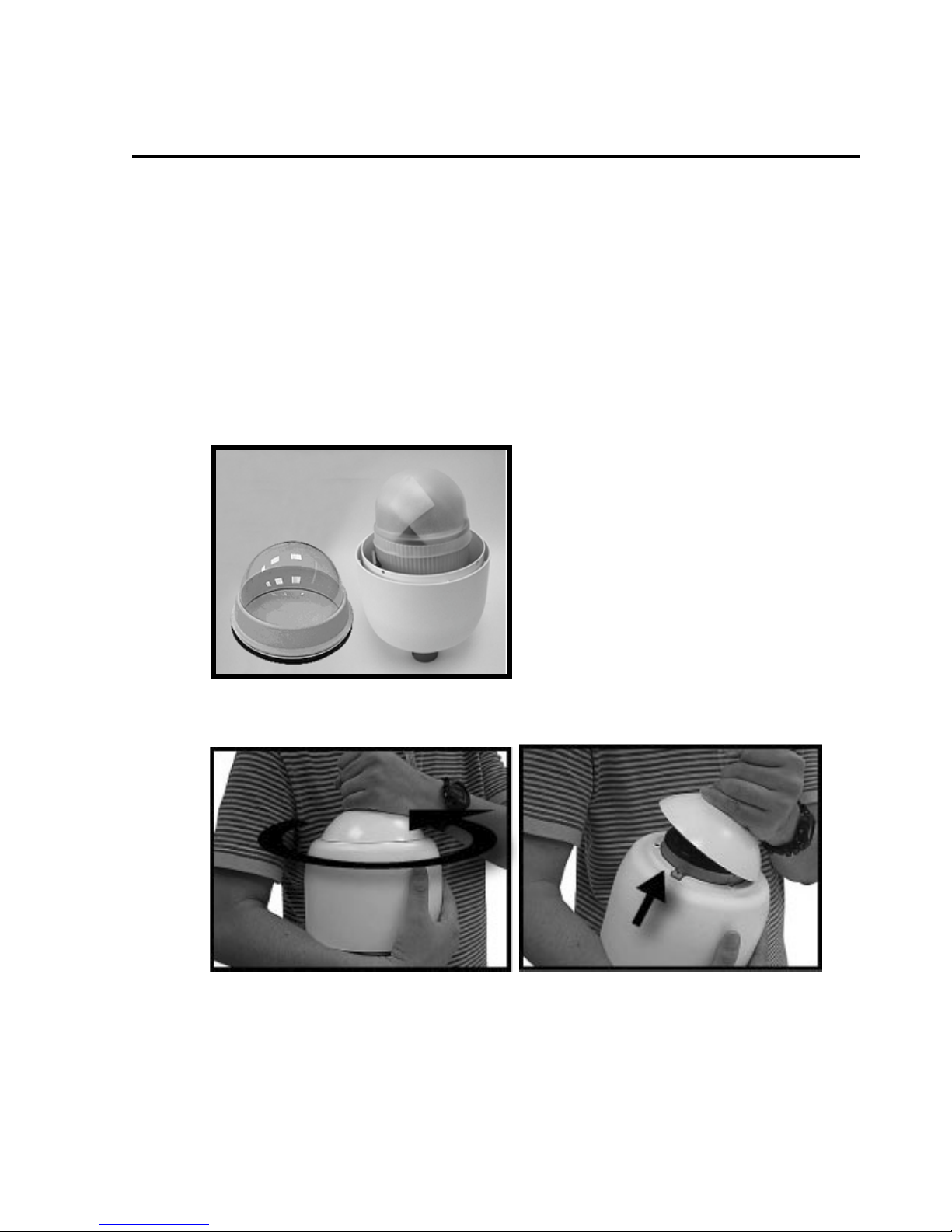
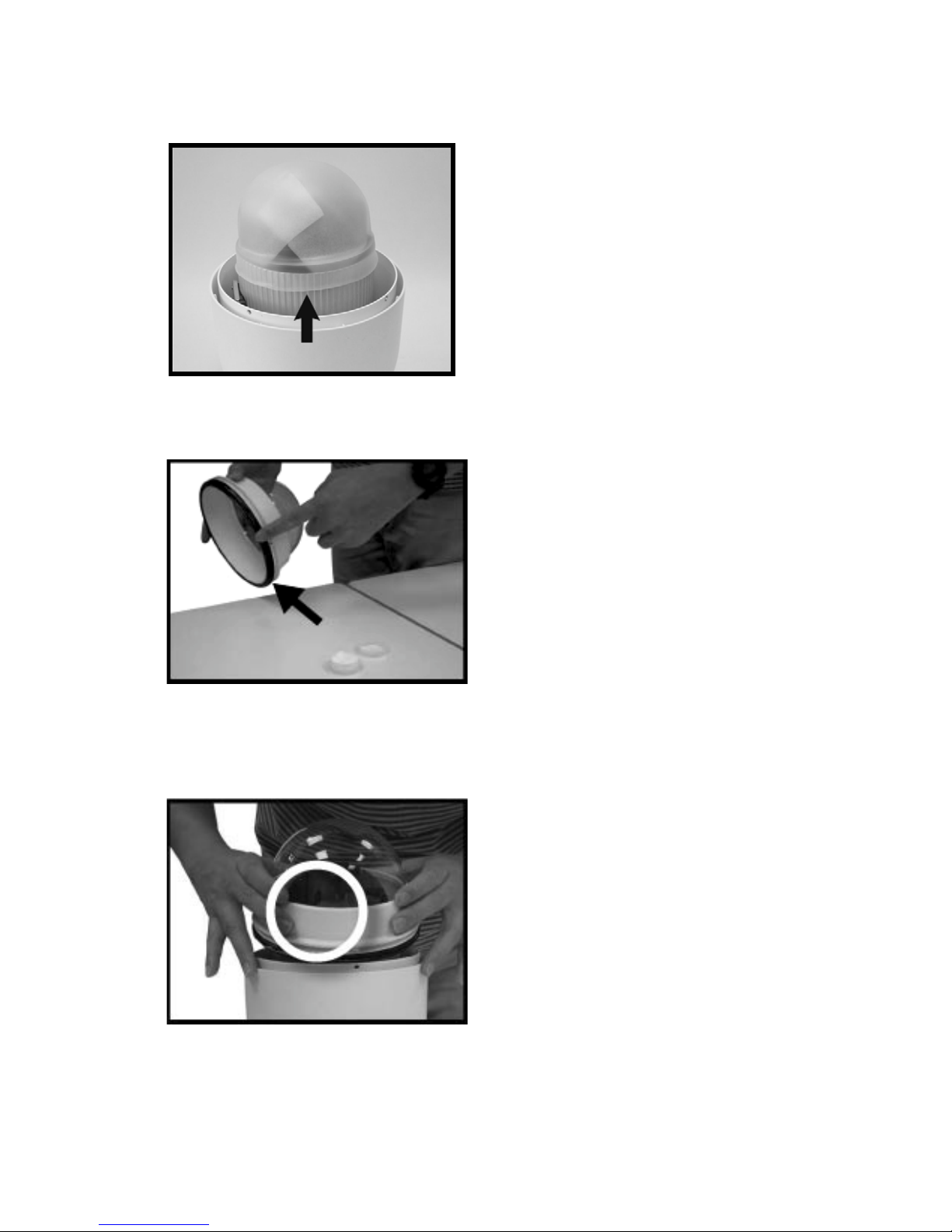
Preparations for Dome Setup
The following installation procedure is for the outdoor dome equipped with the
sunshield housing. Please follow the steps below to complete dome housing
installation.
1. Unpack the dome package and take out the dome body.
2. Rotate the top holder and take it off from the dome body.
14
3. Remove the protective cover and PE sheet.
4. Apply some lubricant on the cover’s waterproof gasket. This helps make
the installation process smoother.
5. Attach the dome cover to the camera body.
6. Note that the tiny protrusion on the cov er mus t align w ith one of the four
holes on the camera body.

31648AB 15
7. Using both hands, gently press the dome cover using both hands.
DO NOT press the dome itself as this may cause damage to the dome or
camera.
8. To secure the dome cover to the camera body, use a screwdriver to
extend the screws outward.
16
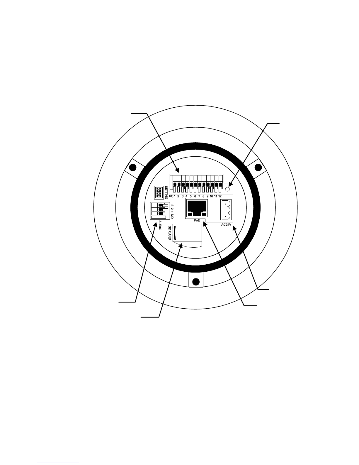
Dome Camera Setup
Switch Definition
Please refer to the following figure for switch location and definitions.
Note Do not change the settings on the camera’s Communication Switch.
Leave the switch at the factory default settings.
Alarm input/output
connections
Audio connection
RJ-45 connector
Reboot
Power connection
SD card

31648AB 17
Dome Cable Definition and Requirements
For operation, the IP dome camera requires a network cable to carry the video
signals to the remote viewing site and a power cable to power the dome.
Cable Requirements
For operation, the CM-L812 IP camera requires AC 24V power to the dome.
Power Wire Length Specifications
Wire
Gauge
Maximum
Distance
Wire
Gauge
Maximum
Distance
22 27 feet 14 175 feet
20 44 feet 12 279 feet
18 69 feet 10 444 feet
16 110 feet
Note Ensure that the power supply corresponds with the dome’s power
requirement or the ca mera ma y be damaged. Contact a qualified
maintenance engineer with any problems.
Network Cable Length Specifications
Cable
Type
Maximum
Distance
Wire
Gauge
Maximum
Distance
CAT5 300 feet CAT6 300 feet
CAT5e 300 feet CAT6a 300 feet
Note An Ethernet crossover cable can be used to connect the camera
directly to a PC during conf igu r ation .

18
Power Connection
1. Connect POSITIVE 24 volt AC power to pin 1.
2. Connect ground wire to pin 2.
3. Connect NEGATIVE 24 volt AC power to pin 3.
Note The ‘notches’ on the left side of the graphic above correspond to
notches in the green plastic of the power connector.
Note Be careful not to pull the cables improperly dur ing ins tal lati on .
OpenEye suggests that you fasten the cables after installation is
complete.
Grounding Recommendation
The GND (ground) wire must be directly connected to the middle pin of the
AC24V power connector. Failure to connect the ground can cause damage and
failure of the camera and may void the warranty.
Ethernet Cable Connection
Connect one end of the CAT 5 Ethernet cable to the RJ-45 connector of the
camera and the other end of the cable to the network switch or recorder.
Note In some cases, you may need to use an Ethernet crossover cable
when connecting the camera directly to the recorder.
Check the status of the link indicator and activity indicator LEDs. If the LEDs are
unlit, check the LAN connection.
The Green link light indicates a good network connection.
The Orange activity light flashes to indicate network activity.
31648AB 19
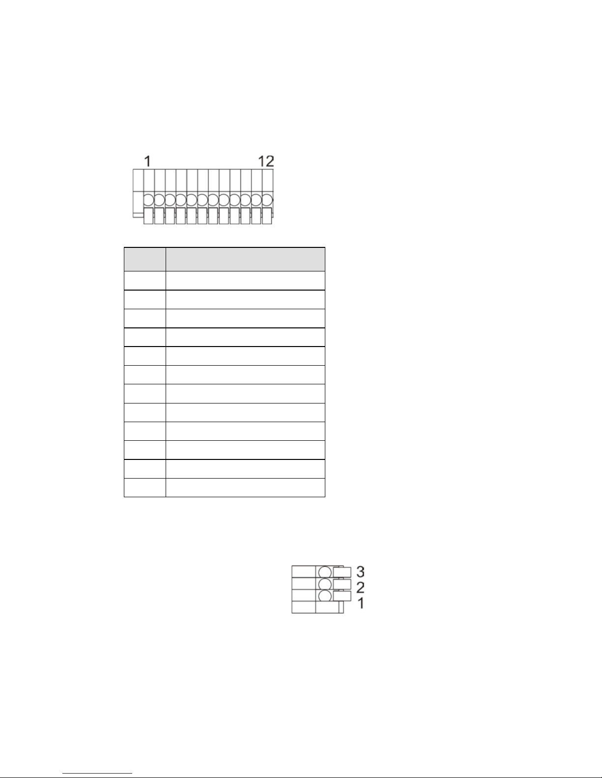
12-Pin Alarm Input/Output Connection
Using the 12-pin connector, installers can connect 4 digital alarm inputs and 2
digital alarm outputs. The alarm pins are serviceable for connecting alarm input
and output devices such as sensors, sirens, or flashing lights to the surveillance
system. For the definition of each pin, refer to the list bel ow.
Pin Definition
1 Alarm OUT NO 1
2 Alarm OUT NC 1
3 Alarm OUT COM 1
4 GROUND
5 Alarm OUT NO 2
6 Alarm OUT NC 2
7 Alarm OUT COM 2
8 GROUND
9 Alarm IN 4
10 Alarm IN 3
11 Alarm IN 2
12 Alarm IN 1
Audio Input/Output Connection
1. Line OUT
2. GROUND
3. Line IN
20
DOME INSTALLATION
OVERVIEW
Depending on your installation environment, the dome can be installed on the
ceiling, on a wall, or a pole. The following section illustrates installation methods
and procedures for installing the dome and mounting accessories.
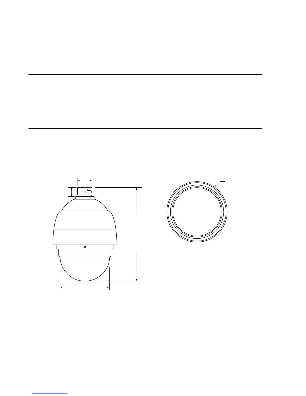
DOME DIMENSIONS
The dome dimensions are Ø172 x 228.71mm (6.77 x 9.0 inches) and Ø191.97 x
282.11mm (7.5 x 11.1 inches) with the sunshield.
11.1” (282 mm)
6.75” (171.5 mm)
1” (25 mm)
1.75” (44.45 mm)
Ø 7.5” (190.5 mm)

31648AB 21
OPTIONAL ACCESSORIES
Dome Camera Accessories
Transparent/Smoke Cover – Part Number: CA-510-DT
Mounting Accessori es
Wall Mount Bracket (w/ Anti Drop) – Part Number: CA-510W
Long Wall Mount Bracket (w/ Anti Drop) – Part Number: CA-510WL
50 cm Pole – Part Number: CA-510P50
25 cm Pole – Part Number: CA-510P25
Corner Mounting Plate – Part Number: CA-510C
Small Pole Mount – Part Number: CA-510PMS
Large Pole Mount – Part Number: CA-510PML
1 ¼” Threaded Adapter – Part Number: CA-510PA25
1 ½” Threaded Adapter – Part Number: CA-510PA50
22
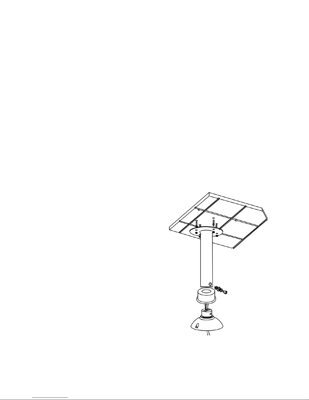
Ceiling Mounting with Pole
The pole is available in two lengths: 25 cm and 30 cm.
Items Needed Tools Needed
Dome Camera Drill
Ceiling Pole Accessory Screwdriver
Waterproof Gasket (supplied)
Screws and anchors appropriate for
the mounting surface (not supplied
Installation Steps:
Note Ensure that the ceiling can support the weight of the dome camera and
the ceiling pole.
1. Cut a cable access hole in the
ceiling.
2. Attach the ceiling pole to the
ceiling with the appropriate
screws and screw anchors (not
provided).
3. Attach the waterproof gas ket t o
the Ceiling Pole.
4. Thread the cables through the
ceiling pole and the top holder
Note After threading the cables
through the tube, block the
cable entry hole with the
supplied sponges to prevent
insects from entering the tube.
5. Attach the top holder to the
ceiling pole with the supplied
screws and washers and adjust
the gasket to the junction of the
ceiling pole and the top holder.
6. Connect the cables to the dome camera.
31648AB 23
7. Attach the dome to the top holder and secure them with the supplied
screw.
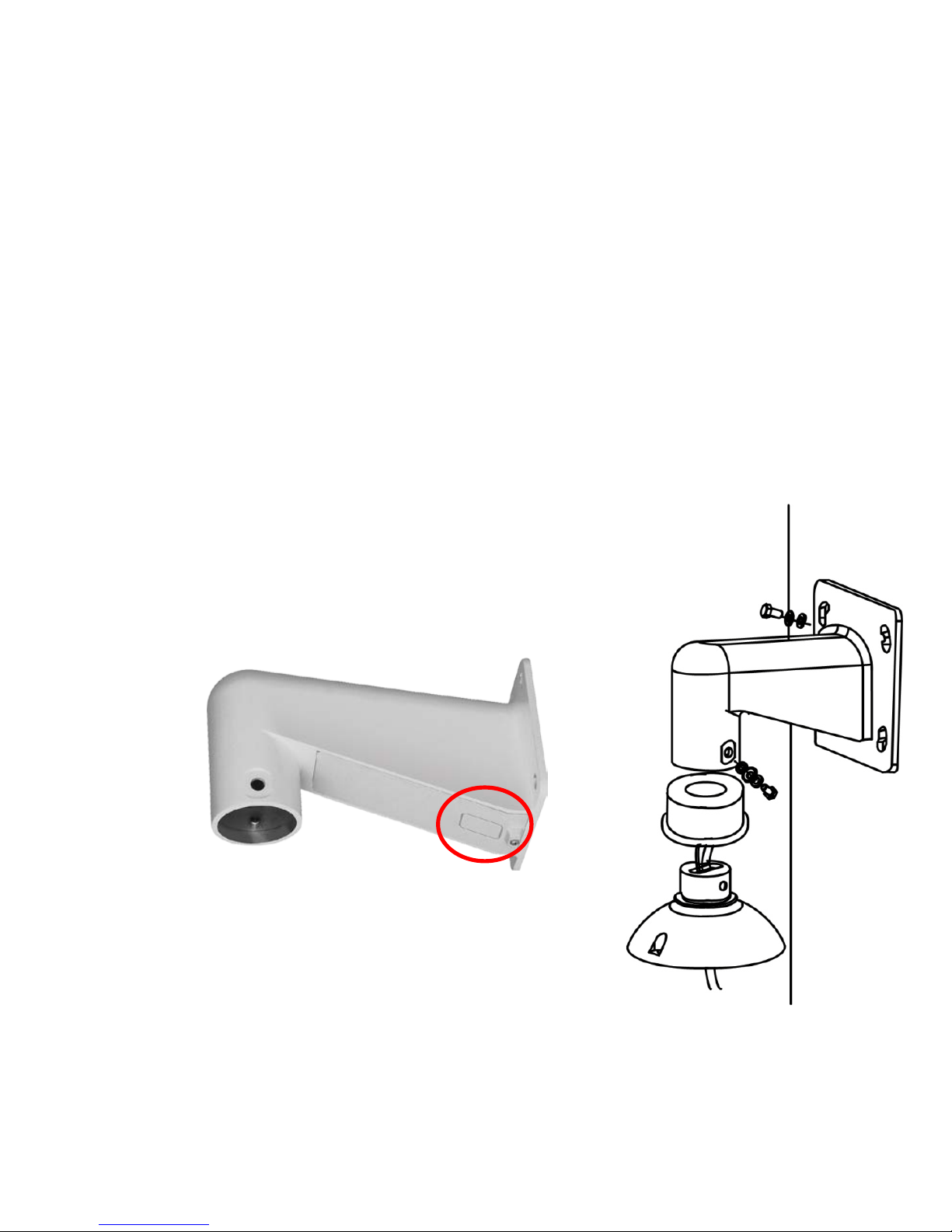
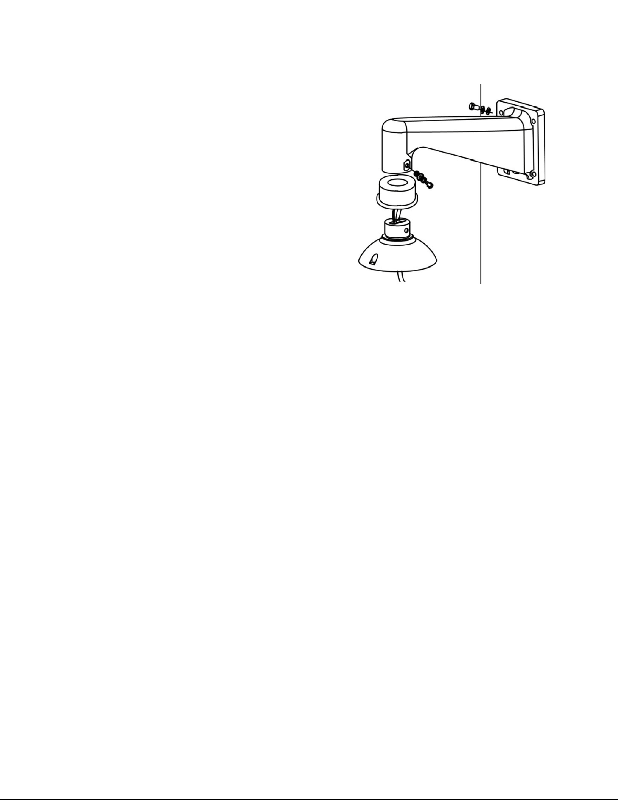
Wall Mounting with Wall Mount Bracket
Items Needed Tools Needed
Dome Camera Drill
Wall Mount Bracket or long wall mount
bracket
Screwdriver
Waterproof Gasket (supplied)
Screws and anchors appropriate for
the mounting surface (not supplied)
Installation:
1. Cut a cable access hole on the wall.
Cables can also be threaded through
the cable entry knockout on the tube if
desired.
2. Thread the cables through the wall
mount bracket.
3. Block the cable entry hole with the
supplied sponge.
24
4. Attach the wall mount bracket to the
wall with the appropriate screws and
screw anchors (not provided).
5. Attach the waterproof gasket to the
wall mount bracket.
6. Thread the cables through the top
holder and attach the dome to the
wall mount bracket with the supplied
screws and washers.
7. Connect the cables to the dome
camera.
8. Attach the dome to the top holder
and secure them with the supplied
screw.
31648AB 25
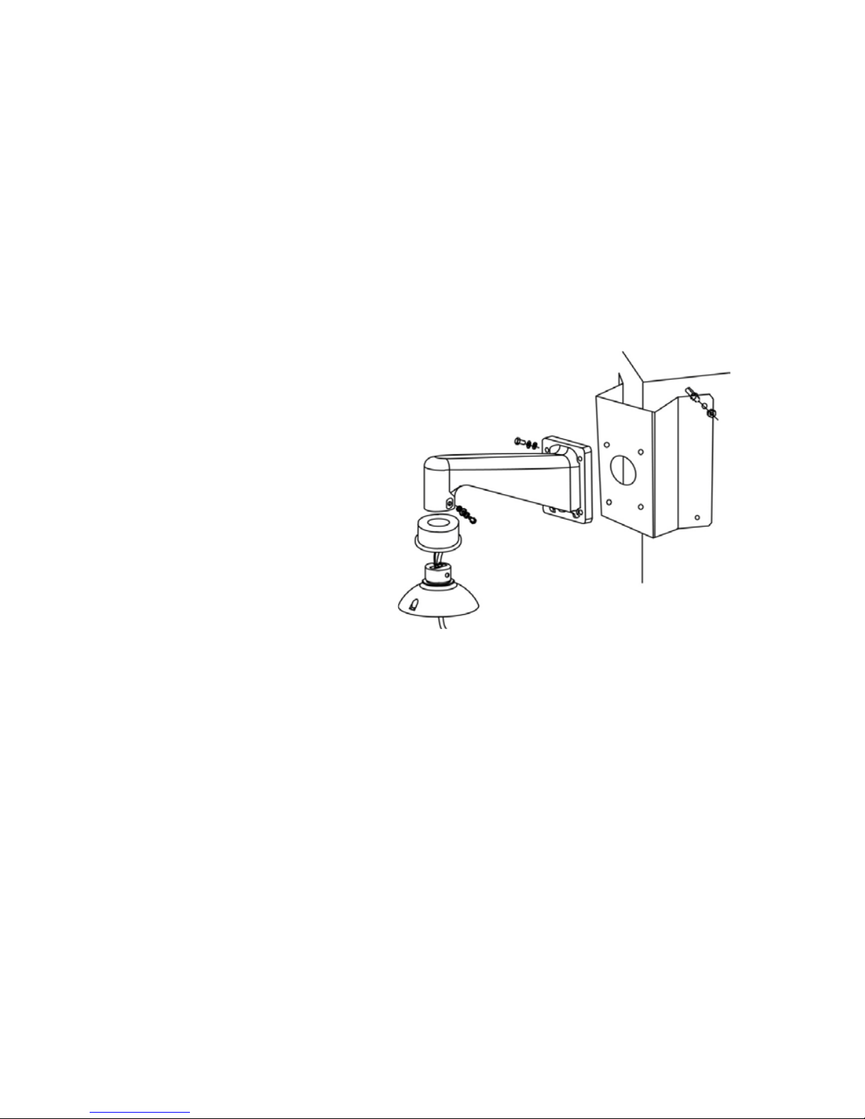
Wall Mounting with Corner Mount
The corner mount must be used in conjunction with the wall mount bracket.
Items Needed Tools Needed
Dome Camera Screws and anchors appropriate for
the mounting surface (not supplied)
Wall Mount Bracket Accessory
Corner Mounting Plate
Waterproof Gasket (supplied)
Installation:
1. Cut a cable access hole on the wall. Cables can also be threaded
through the cable entry knockout on the bracket if desired.
2. Secure the corner mount plate on the corner wall with the appropriate
screws and screw anchors.
3. Attach the wall mount bracket to the corner mount plate with the
supplied screws and washers.
4. Thread the cables through wall mount bracket and the top holder.
5. Block the cable entry hole with the supplied sponge.
6. Attach the waterproof gasket to the wall mount bracket.
7. Attach the top holder to the wall mount bracket with the supplied screws
and washers and adjust the gasket to the junction of the wall mount
bracket and the top holder.
8. Connect the cables to the dome camera.
9. Attach the dome to the top holder and secure them with the supplied
screw.
26
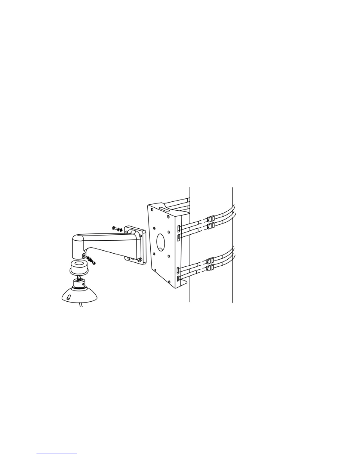
Pole Mounting
The dome can be mounted on a pole with the small or large direct mounting
accessory and a wall mount bracket.
Items Needed Tools Needed
Dome Camera Stainless Steel Strap Cutter
Wall Mount Bracket Accessory Screwdriver
Small/Large Pole Mount Accessory
Stainless Steel Straps
Waterproof Gasket (supplied)
Installation Steps:
1. Fasten the small/large pole mount to the pole with st ain les s stee l straps .
2. Attach the wall mount bracket to the pole mount with the supplied
screws and washers.
3. Attach the waterproof gasket to the wall mount bracket.
4. Thread the cables through the wall mount and the top holder.
5. Block the cable entry hole with the supplied sponge.
6. Attach the top holder to the wall mount with the supplied screws and
washers and adjust the gasket to the junction of the wall mount and the
top holder.
7. Connect the cables to the dome camera.

31648AB 27
8. Attach the dome to the top holder and secure them with the supplied
screw.
LOCATE CAMERA
OPENEYE NETWORK CAMERA MANAGER
Use the included Network Camera Manager software to easily find your network
cameras for initial setup. The OpenEye IP Finder software is included on the CD
with all OpenEye IP devices.
Installation
You can install Network Camera Manager on any personal computer (PC) or
laptop using the software CD included with your OpenEye IP camera or by
downloading the program from openeye.net.
Note Network Camera Manager will only work on PCs or laptops that use a
Windows operating system. It is compatible with Windows XP, Vista, 7,
and 8.
Starting Network Camera Manager
After installing the program on your PC or laptop, open the program to begin
configuring your cameras.
To access Network Camera Manager on an OpenEye recorder, you must
operate the recorder in Windows Mode.
9. In the Live Screen, click Exit.
10. Click Restart in Windows Mode.
11. Click OK.
12. Double-click Network Camera Manager.
28
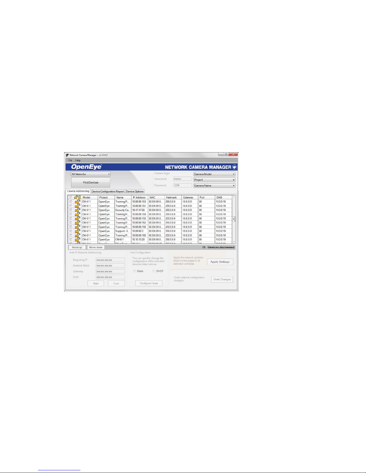
Device Addressing
The functions on the Device Addressing tab allow you to find, configure, and view
network cameras.
Finding Network Devices
13. Click Find Devices on the Device Addressing tab.
14. To narrow your search by Camera Model, Project, or Camera Name,
select your desired criteria from the appropriate lists.
 Loading...