

Page 1
Outdoor Speed Dome Camera
User Manual
Camera
CM-814
Accessories
CA-510G
CA-510W
CA-510C
CA-510P25
CA-510P50
CA-510PML
CA-510PMS
CA-510PA25
CA-510PA50
www.openeye.net
Page 2

2
Page 3

36x Outdoor IP PTZ Camera (CM-814)
User Manual
Manual Edition 30101AB – OCTOBER 2010
©2000-2010, OPENEYE
All Rights Reserved.
No part of this documentation may be reproduced in any means, electronic or mechanical, for
any purpose, except as expressed in the Software License Agreement. OpenEye shall not be
liable for technical or editorial errors or omissions contained herein. The information in this
document is subject to change without notice.
The information in this publication is provided “as is” without warranty of any kind. The entire
risk arising out of the use of this information remains with recipient. In no event shall
OPENEYE be liable for any direct, consequential, incidental, special, punitive, or other
damages whatsoever (including without limitation, damages for loss of business profits,
business interruption or loss of business information), even if OPENEYE has been advised of
the possibility of such damages and whether in an action or contract or tort, including
negligence.
This documentation is copyrighted. All other rights are reserved to OPENEYE. OPENEYE,
and OpenEye, are registered trademarks of OPENEYE in the United States and elsewhere;
Windows, and Windows XP Embedded are registered trademarks of Microsoft Corporation.
All other brand and product names are trademarks or registered trademarks of the respective
owners.
OPENEYE
Liberty Lake, WA ● U.S.A.
30101AB 3
Page 4

Important Safeguards
1. Read Instructions
Read all of the safety and operating instructions before using the product.
2. Retain Instructions
Save these instructions for future reference.
3. Attachments / Accessories
Do not use attachments or accessories unless recommended by the appliance
manufacturer as they may cause hazards, damage product and void warranty.
4. Installation
Do not place or mount this product in or on an unstable or improperly supported
location. Improperly installed product may fall, causing serious injury to a child
or adult, and damage to the product. Use only with a mounting device
recommended by the manufacturer, or sold with the product. To insure proper
mounting, follow the manufacturer's instructions and use only mounting
accessories recommended by manufacturer.
5. Power source
This product should be operated only from the type of power source indicated
on the marking label.
Precautions
Operating
• Before using, make sure power supply and others are properly connected.
• While operating, if any abnormal condition or malfunction is observed, stop
using the camera immediately and then contact your local dealer.
Handling
• Do not disassemble or tamper with parts inside the camera.
• Do not drop or subject the camera to shock and vibration as this can damage
camera.
• Do not block the cooling holes on the bracket. This camera has a cooling fan
inside the housing. Blocking the cooling holes will cause heat to build up and
cause malfunction.
• Care must be taken when you clean the clear dome cover. Scratches and dust
will ruin the image quality of your camera. Do not use strong or abrasive
detergents when cleaning the camera body. Use a dry cloth to clean the
camera when it is dirty. In case the dirt is hard to remove, use a mild detergent
and wipe the camera gently.
4
Page 5

Installation and Storage
• Install electricity wiring carefully. Please note that input electricity to the unit is at
tolerance of DC 12V/AC 24V ± 10%. The camera is capable of surge protection;
ensure AC power model unit is grounded appropriately against damage by
heavy current or electric shock.
• Do not install the camera in areas of extreme temperatures in excess of the
allowable range. (-50°C ~50°C / -58°F ~ 122°F)
• Avoid installing in humid or dusty places. The relative humidity must be below
90%.
• Avoid installing in places where radiation is present.
• Avoid installing in places where there are strong magnetic fields and electric
signals.
• Avoid installing in places where the camera would be subject to strong
vibrations.
• Never face the camera toward the sun. Do not aim at bright objects. Whether
the camera is in use or not, never aim it at the sun or other extremely bright
objects. Otherwise the camera may be smeared and damaged.
Regulation
This device complies with Part 15 of the FCC Rules. Operation is subject to the
following two conditions: (1) this device may not cause harmful interference, and
(2) this device must accept any interference received, including interference that
may cause undesired operation.
This symbol on the product or on its packaging indicates that this
product shall not be treated as household waste in accordance with
Directive 2002/96/EC. Instead it shall be handed over to the
applicable collection point for the recycling of electrical and
electronic equipment. By proper waste handling of this product you
ensure that it has no negative consequences for the environment
and human health, which could otherwise be caused if this product
is thrown into the garbage bin. The recycling of materials will help to
conserve natural resources.
For more details information about recycling of this product, please
contact your local city office, your household waste disposal service
or the shop where you purchased the product.
Compliance is evidenced by written declaration from our suppliers,
assuring that any potential trace contamination levels of restricted
substances are below the maximum level set by EU Directive
2002/95/EC, or are exempted due to their application.
30101AB 5
Page 6
Warning
DANGEROUS HIGH VOLTAGES ARE PRESENT INSIDE THE ENCLOSURE.
DO NOT OPEN THE CABINET.
REFER SERVICING TO QUALIFIED PERSONNEL ONLY.
Caution
CAUTION
RISK OF ELECTRIC SHOCK
DO NOT OPEN
CAUTION: TO REDUCE THE RISK OF ELECTRIC SHOCK,
DO NOT REMOVE C OVER (OR BACK).
NO USER-SERVICEABLE PARTS INSIDE.
REFER SERVICING T O QUALIF I ED SER VICE PERSONNEL.
6
Page 7

Standard Warranty
OpenEye warrants all new products to be free from defects in workmanship and
material under normal use for a period of two years after the date of purchase. Any
defective product that falls under this warranty will, at OpenEye's discretion, be
repaired or replaced at no additional charge. OpenEye may elect to replace defective
products with new or factory reconditioned products of equal or greater value.
Repairs made necessary by reason of misuse, alteration, normal wear, or accident
are not covered under this warranty.
Exceptions to this are listed below:
• Three Years on all Digital Recorders
• Three years on all fixed cameras
All products shall be covered by a one year advance replacement warranty*.
OpenEye will warrant all otherwise out of warranty replacement parts and repairs for
90 days from the date of OpenEye shipment.
The above warranty is the sole warranty made by OpenEye and is in lieu of all other
warranties by OpenEye express and implied, including without limitation the
warranties of merchantability and fitness for a particular purpose. Under no
circumstances will OpenEye be liable for any consequential, incidental, special or
exemplary damages arising out of or connected with the sale, delivery, use or
performance of the product, even if OpenEye is apprised of the likelihood of such
damages occurring. In no event shall OpenEye liability exceed the purchase price of
the product.
This warranty gives you specific legal rights and you may also have other rights
which vary from state to state or country to country.
*Requires corresponding security deposit. Advanced Replacement limited to
components only outside of the USA and Canada.
For the most up to date information visit www.openeye.net
30101AB 7
Page 8

TABLE OF CONTENTS
Table of Contents ............................................................................... 8
Introduction ...................................................................................... 12
Overview ............................................................................................................... 12
Product Features .............................................................................................. 12
General Operation Requirements ......................................................................... 13
System Configuration ....................................................................................... 13
Getting Started ................................................................................. 14
Camera Contents .................................................................................................. 14
Dome Setup and Cable COnnection .................................................................... 15
Preparations for Dome Setup ........................................................................... 15
Dome Camera Setup ........................................................................................ 18
Switch Definition ........................................................................................... 18
Dome Cable Definition and Requirements ....................................................... 19
Cable Requirements .................................................................................... 19
22-Pin Data Cable ........................................................................................ 19
22-Pin Connector Definition ......................................................................... 20
Cable Wiring and Connection ...................................................................... 21
Ethernet Cable Connection .......................................................................... 22
Grounding Recommendation ....................................................................... 22
Dome Installation ............................................................................. 23
Overview ............................................................................................................... 23
Dome Dimensions ................................................................................................ 23
Optional Accessories ............................................................................................ 24
Dome Camera Accessories .............................................................................. 24
Mounting Accessories ...................................................................................... 24
Ceiling Mounting with Pole ............................................................................... 28
Wall Mounting with Wall Mount Bracket ........................................................... 29
Wall Mounting with Corner Mount .................................................................... 31
Pole Mounting ................................................................................................... 32
Camera Finder .................................................................................. 33
OpenEye IP Finder ............................................................................................... 33
8
Page 9

Finding IP Cameras .......................................................................................... 33
Default Username and Password ................................................................ 33
Changing the Network Type ............................................................................. 34
Setup & Configuration .................................................................... 34
Connecting to the Camera .................................................................................... 34
Administrator/User Privileges ........................................................................... 34
Viewer Software .................................................................................................... 35
Viewer Tabs ...................................................................................................... 35
Home Page ........................................................................................................... 36
System Related Settings ....................................................................................... 38
Host Name and System Time Setting .............................................................. 38
Security ............................................................................................................. 39
Admin Password .......................................................................................... 39
Add User ...................................................................................................... 40
Delete user ................................................................................................... 40
Edit user ....................................................................................................... 40
Network ............................................................................................................. 41
Get IP address automatically (DHCP) .......................................................... 41
Use fixed IP address .................................................................................... 41
DDNS ................................................................................................................ 43
Mail ................................................................................................................... 44
FTP ................................................................................................................... 45
Application (Alarm Settings) ............................................................................. 46
Alarm Pin Selection ...................................................................................... 47
Alarm Status Settings ................................................................................... 48
Snapshot ........................................................................................................... 50
View Log File .................................................................................................... 51
View User Information ...................................................................................... 52
View User Login Information ........................................................................ 52
View User Privilege ...................................................................................... 52
View Parameters .............................................................................................. 53
Factory Default ................................................................................................. 54
Set Default .................................................................................................... 54
Reboot .......................................................................................................... 54
Software Version .............................................................................................. 55
Software Upgrade ............................................................................................. 56
30101AB 9
Page 10

Upgrading the Camera Viewer Software ..................................................... 56
Video and Audio Streaming Settings .................................................................... 57
Video Resolution and Video Deinterlacing Function ........................................ 57
Video Compression .......................................................................................... 58
Video OCX Protocol ......................................................................................... 59
Multicast Mode ............................................................................................. 59
Video Frame Skip ............................................................................................. 60
Audio Mode and Bit Rate Settings ................................................................... 61
Transmission Mode ...................................................................................... 61
Bit Rate ......................................................................................................... 61
PTZ Settings ......................................................................................................... 62
Preset Programming ......................................................................................... 62
Preset Setting ............................................................................................... 62
Preset Go ..................................................................................................... 63
Cruise Programming ......................................................................................... 63
Cruise Setting ............................................................................................... 63
Cruise Run ................................................................................................... 64
Auto Pan Programming .................................................................................... 64
Auto Pan Setting .......................................................................................... 65
Auto Pan Run ............................................................................................... 65
Sequence Line Programming ........................................................................... 66
Sequence Setting ......................................................................................... 67
Sequence Run ............................................................................................. 67
Home Function ................................................................................................. 68
Home Setting ............................................................................................... 68
Tilt Angle Settings ............................................................................................. 69
Privacy Mask Settings ...................................................................................... 70
Mask Setting ................................................................................................ 71
Mask Clearing .............................................................................................. 71
Camera—Exposure Mode ................................................................................ 72
Camera—White Balance Mode ........................................................................ 73
Camera—Miscellaneous Setup Menu 1 ........................................................... 74
Camera—Miscellaneous Setup Menu 2 ........................................................... 76
Default Settings ................................................................................................ 77
Logout ................................................................................................................... 77
10
Page 11

Specifications .................................................................................. 78
Camera Specifications .......................................................................................... 78
PTZ Specifications ................................................................................................ 79
IP Specifications ................................................................................................... 79
30101AB 11
Page 12

INTRODUCTION
OVERVIEW
With an IP66 rating, the CM-814 Outdoor PTZ IP Camera is suitable for outdoor
installations. The CM-814 IP camera can transmit video at H.264 and MJPEG, dual
streaming both codecs at D1 at 30IPS. The camera’s IR cut filter and wide dynamic rage
imaging make it perfect for installations with difficult lighting conditions. The CM-814 has
an IP66 outdoor rating and integrated heater making the 814 ideal for rugged outdoor
installations with temperature as low as -49°F (-45°C)
Product Features
• 36x Optical Zoom
• Simultaneous dual streams: H.264 and MJPEG
• D1 Real-time Resolution
• 3D de-interlaced video image
• Two-way audio support
• Removable IR Cut Filter
• Wide Dynamic Range (WDR)
• 3D Noise Reduction
12
Page 13
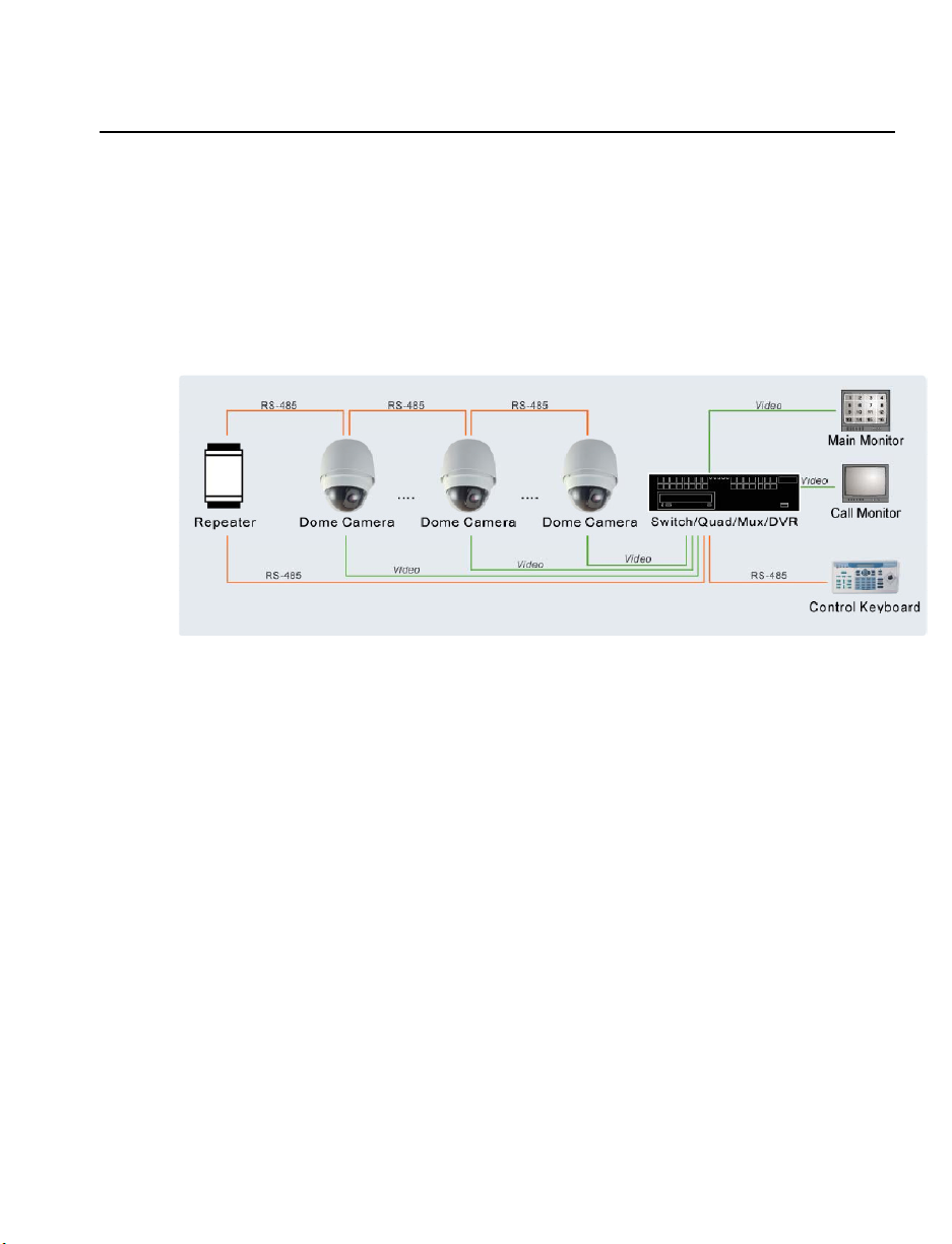
GENERAL OPERATION REQUIREMENTS
A minimum of one control device is required for operation, such as a control keyboard,
or a DVR. The integrated high speed dome camera contains a built-in receiver that
decodes commands from a control device.
Connect dome cameras to other devices, as shown in the diagram below, to complete a
video surveillance system.
System Configuration
30101AB 13
Page 14
GETTING STARTED
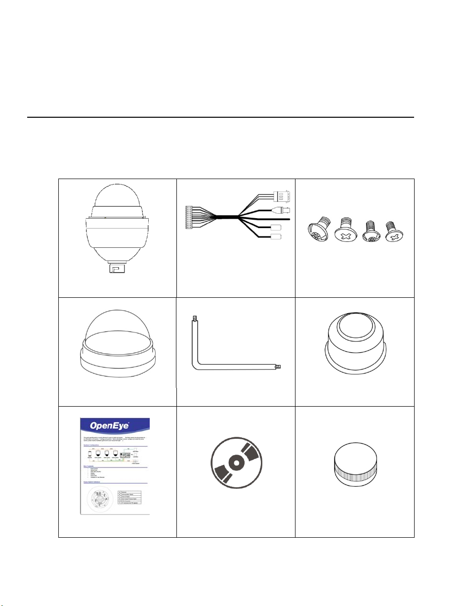
CAMERA CONTENTS
Before proceeding, please check that the box contains the items listed here. If any item
is missing or has defects, DO NOT install or operate the product and contact your dealer
for assistance.
Dome Body Screws
Optical Cover Security Torx Tool Waterproof Gasket
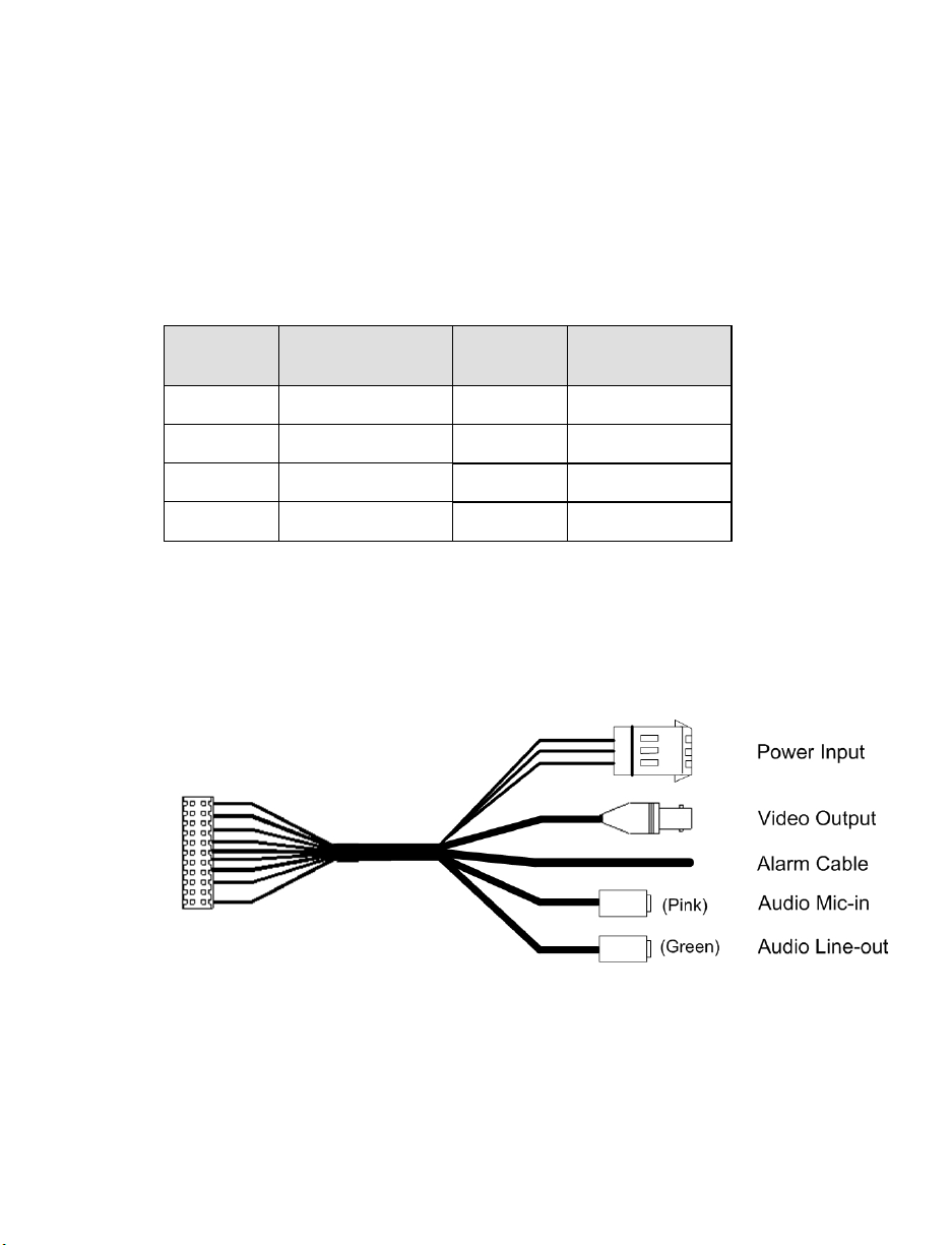
All-in-one Data Cable for
power supply, video and
audio and alarm. (AC 24V)
Quick Start Guide CD Lubricant
14
Page 15
DOME SETUP AND CABLE CONNECTION
Before installing or connecting the dome camera, please refer to this section and
complete preparations for dome setup and all switch settings.
Preparations for Dome Setup
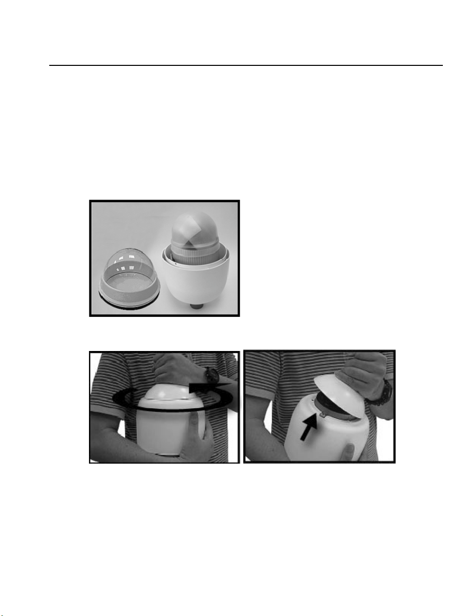
The following installation procedure is for the outdoor dome equipped with the sunshield
housing. Please follow the steps below to complete dome housing installation.
1. Unpack the dome package and take out the dome body.
2. Rotate the top holder and take it off from the dome body.
30101AB 15
Page 16
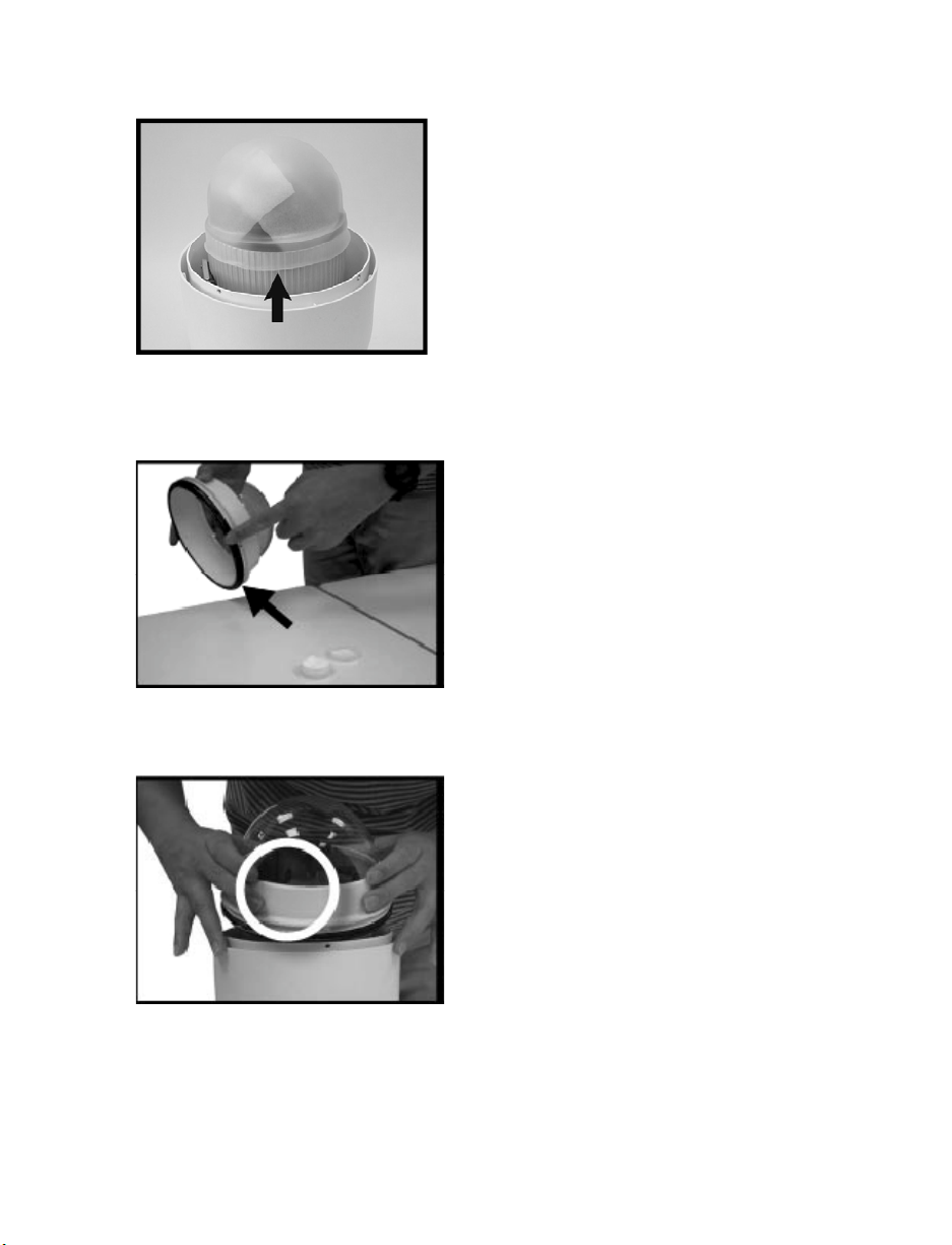
3. Remove the protective cover and PE sheet.
4. Attach the dome cover to the camera body. Before doing that, apply some lubricant
on the cover’s waterproof gasket. This helps make the installation process
smoother.
5. Note that the tiny protrusion on the cover must align with one of the four holes on
the camera body.
16
Page 17
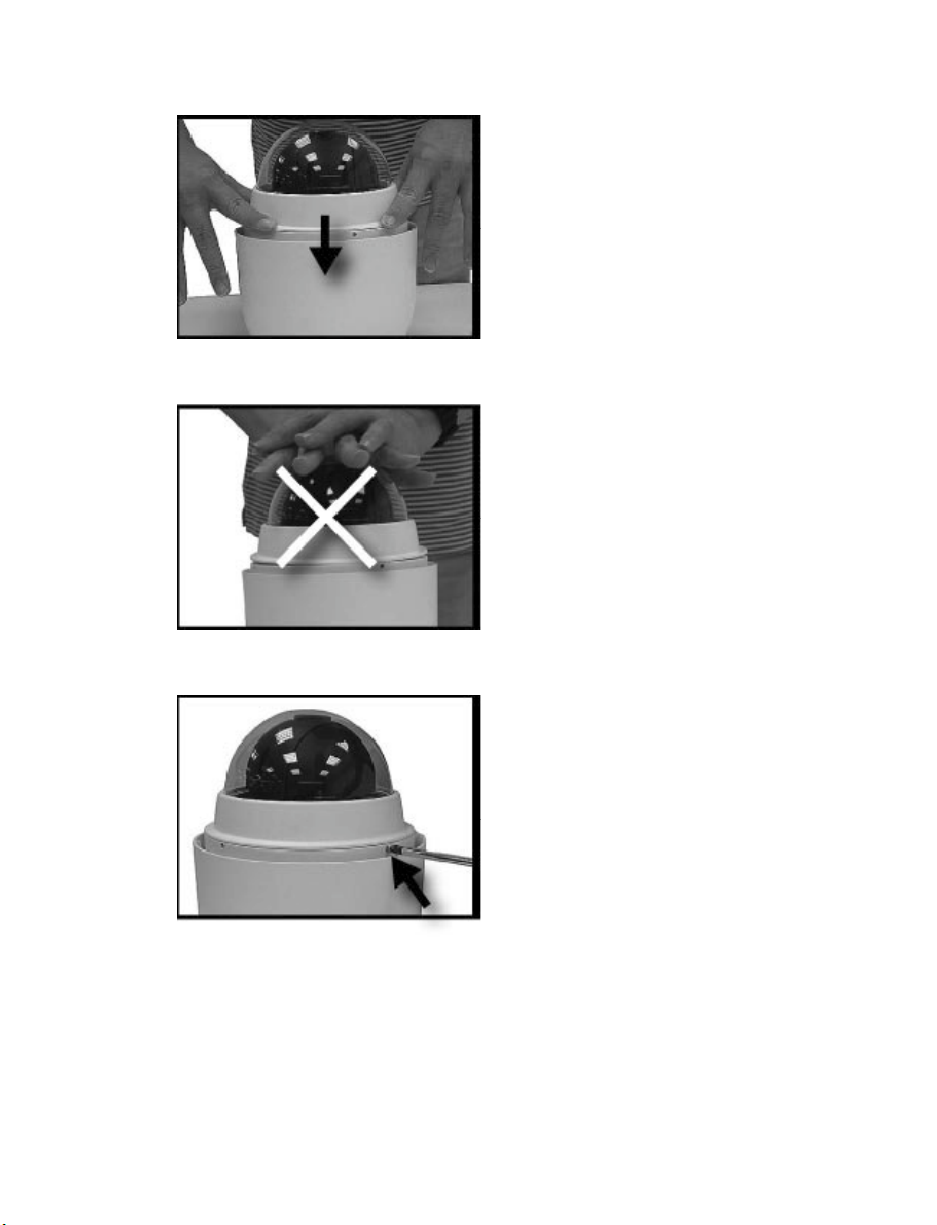
6. Using both hands, gently press the dome cover using both hands.
DO NOT press the cover as shown below; this may cause damage to the dome camera.
7. Screw the dome cover and body together.
30101AB 17
Page 18
Dome Camera Setup
Switch Definition
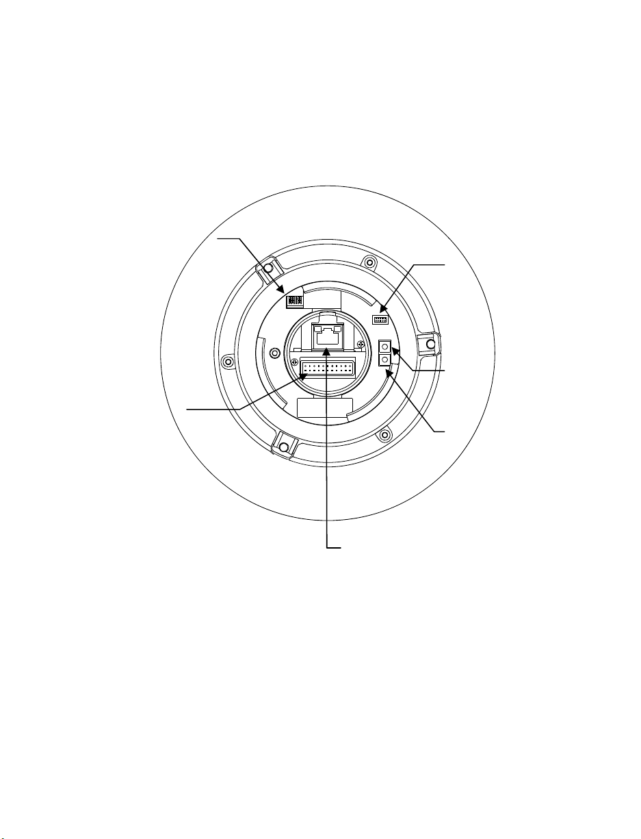
Please refer to the following figure for switch location and definitions.
Communication
Switch (reserved)
22-pin Connector
ISP Connector
(for firmware upgrade)
Reboot
Reset Factory
Settings
18
RJ-45 Connector
Note Do not change the settings on the camera’s Communication Switch. Leave the
switch at the factory default settings.
Page 19
Dome Cable Definition and Requirements
For operation, the IP dome camera requires a network cable to carry the video signals to
the remote viewing site and a power cable to power the dome.
Cable Requirements
For operation, the CM-814 IP camera requires AC 24V power to the dome.
Power Wire Length Specifications
Wire
Gauge
22 27 feet 14 175 feet
20 44 feet 12 279 feet
18 69 feet 10 444 feet
16 110 feet
Note Ensure that the power supply corresponds with the dome’s power requirement
Maximum
Distance
or the camera may be damaged. Contact a qualified maintenance engineer
with any problems.
22-Pin Data Cable
Wire
Gauge
Maximum
Distance
Note Be careful not to pull the cables improperly during installation. OpenEye
suggests that you fasten the cables after installation is complete.
Note When wiring the power cable, make sure the Ground wire is inserted into the
mid-pin of the terminal block.
30101AB 19
Page 20
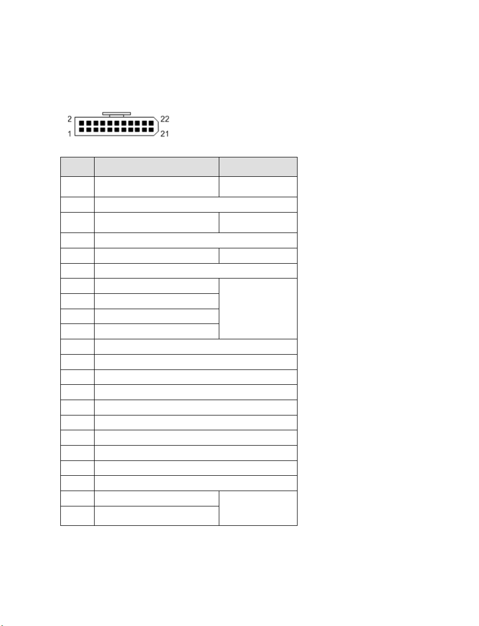
22-Pin Connector Definition
Using the 22-pin connector, installers can connect the power, video, and RS-485 cables
in one place. The alarm pins are serviceable for connecting alarm input and output
devices such as sensors, sirens, or flashing lights to the surveillance system. For the
definition of each pin, refer to the list below.
Pin Definition Cable
1
2 ALM NC
3
4 ALM NO
5 FG 20AWG/18AWG
6 ALM COM
7 Audio In
8 Audio Out
9 Audio GND
10 Audio GND
11 ISOG
12 ALM-1
13 ALM-3
14 ALM-2
15 ALM-4
16 Reserved
17 Reserved
18 Reserved
19 Reserved
20 ALM GND
21 VGND
22 Video
AC 24-1/DC (+)
AC 24-2/DC (-)
20AWG/18AWG
20AWG/18AWG
24AWG
20AWG
20
Note For alarm connections, refer to the Cable Wiring and Connection section.
Page 21
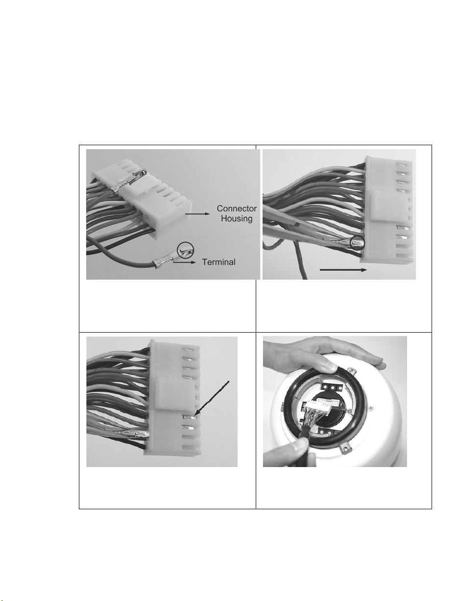
Cable Wiring and Connection
You may need to connect cable wiring when:
• Connecting self-provided cords to the connector housing instead of using the
supplied data cable
• Connecting alarm input and output devices.
The following table illustrates the proper way to wire cords into the connector housing.
1. Insert the terminal into the pin holes
on the connector housing, with the
hook outward, as indicated in the
figure.
1a. To unlock the terminal, press the
hook, as indicated in the figure, with
a proper tool and pull it out gently.
30101AB 21
2. Connect the 22-pin connector to the
dome camera.
Page 22
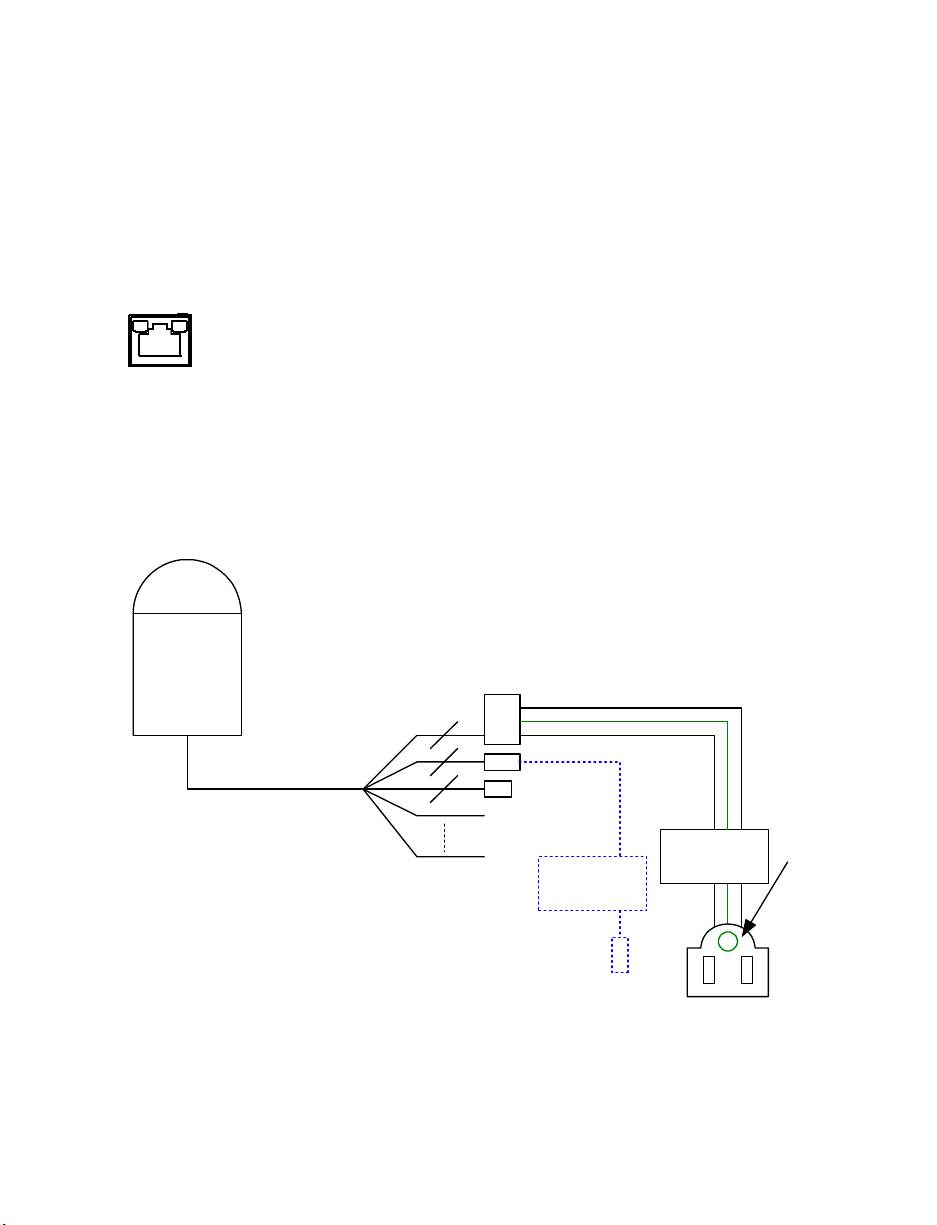
Ethernet Cable Connection
Connect one end of the CAT 5 Ethernet cable to the RJ-45 connector of the camera and
the other end of the cable to the network switch or recorder.
Note In some cases, you may need to use an Ethernet crossover cable when
connecting the camera directly to the recorder.
Check the status of the link indicator and activity indicator LEDs. If the LEDs are unlit,
check the LAN connection.
The Green link light indicates a good network connection.
The Orange activity light flashes to indicate network activity.
Grounding Recommendation
The GND (ground) wire must be directly connected to the middle pin of the AC24V
power connector. Failure to connect the ground can cause damage and failure of the
camera and may void the warranty.
If the connection of the GND wire causes video noise, use a video isolator. This is only
necessary in some situations.
22
AC 24V
3
2
4
Alarm I/O
Optional
3 pins terminal block
VIDEO OUT
RS-485
Video
Adapter
Isolator
VIDEO OUT
AC 24V•
Must be
connected
to ground
(GND)
Page 23
DOME INSTALLATION
OVERVIEW
Depending on your installation environment, the dome can be installed on the ceiling, on
a wall, or a pole. The following section illustrates installation methods and procedures
for installing the dome and mounting accessories.
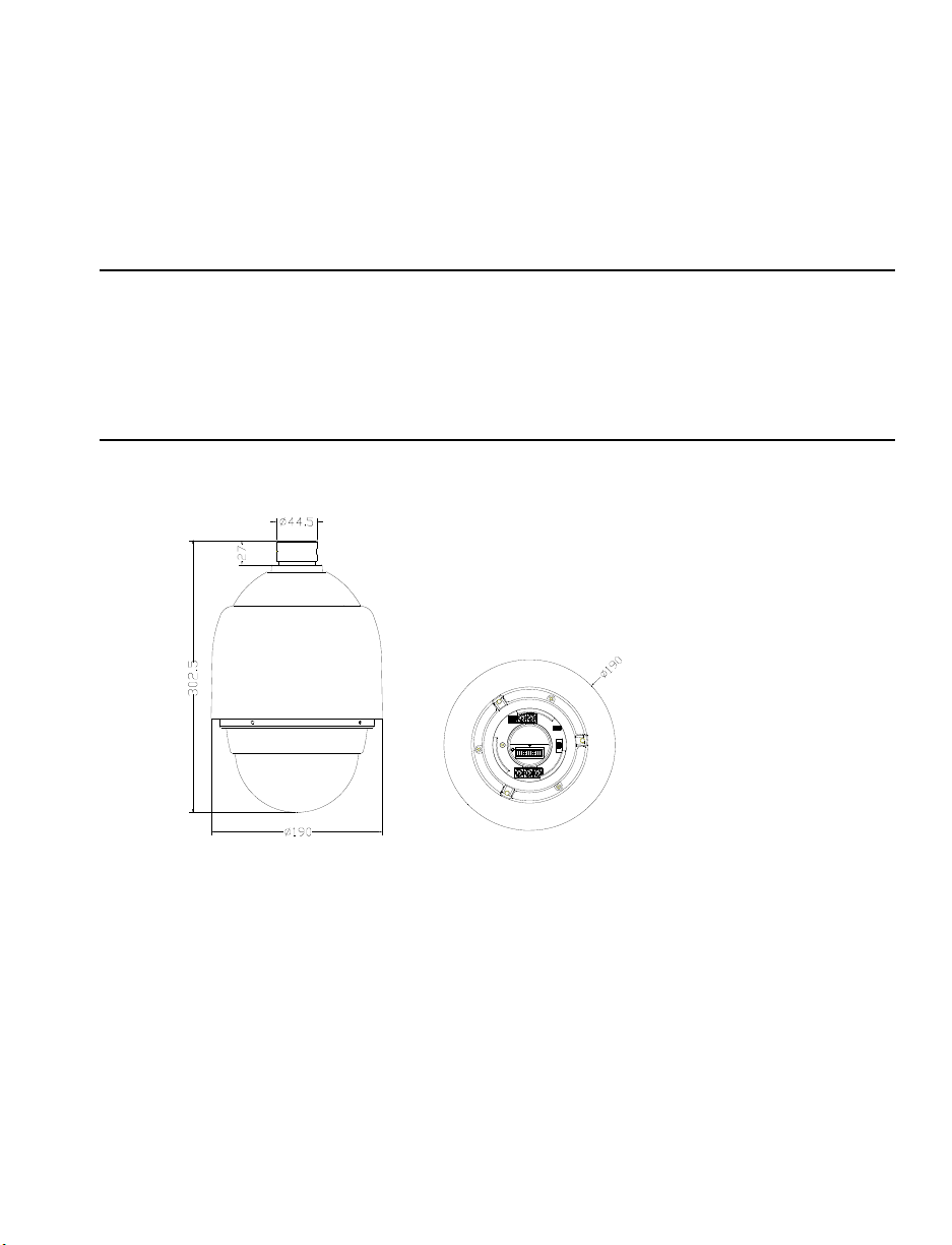
DOME DIMENSIONS
The dome dimensions are Ø172 x 302.5mm (6.7 x 11.9 inches) and Ø190 x 302.5mm
(7.5 x 11.9 inches) with the sunshield.
30101AB 23
Page 24
OPTIONAL ACCESSORIES
Dome Camera Accessories
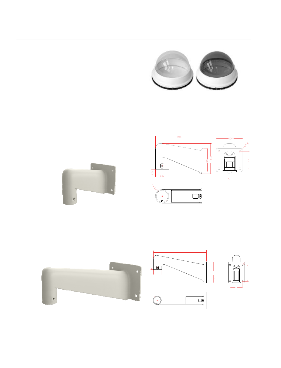
Transparent/Smoke Cover
Diameter: 137 mm (5.4 inches)
Mounting Accessories
Wall Mount Bracket (w/ Anti Drop)
184×104×115.2 mm (7.2”×4.1”×4.5”); 0.6 kg (1.2 lbs)
Supplied with rubber washer-8×1, pendant tube washer×1, spring washer-8×1 and
M8*12 screw×1.
Long Wall Mount Bracket (w/ Anti Drop)
348×104×138.6 mm (13.7”×4.1”×5.5”); 1.5 kg (3.3 lbs)
Supplied with rubber washer-8×1, pendant tube washer×1, spring washer-8×1 and
M8*12 screw×1.
348
5
.
8
ø
24
12.5
ø52
ø
45.2
138.6
98.5
81
Page 25
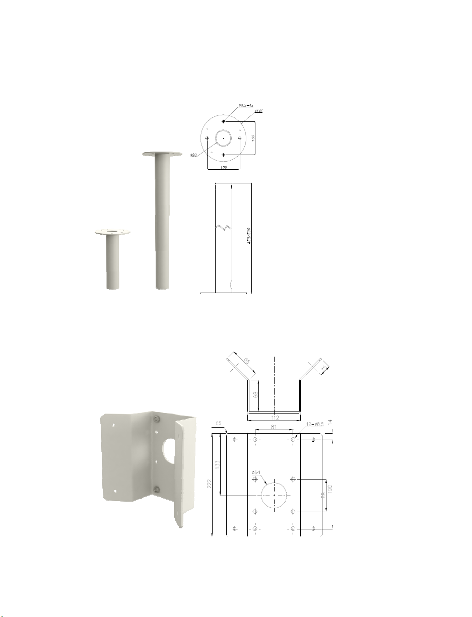
Pole
Iron, Height: 250/500 mm (9.8/19.7 inches) ,Diameter: 50 mm (2 inches) 1 kg (2.2 lbs) /
1.8 kg (4 lbs)
Supplied with rubber washer-8×1, pendant tube washer×1, spring washer-8×1 and
M8*12 screw×1.
Corner Mounting Plate
222(L)×204(W)×117(D) mm (8.7×8×4.6 inches); 2 kg (4.4 lbs)
Supplied with washer-8×4,spring washer×4, M8*16 screw×4, M8 nut×4.
30101AB 25
Page 26

Small Pole Mount
232(L)×136(W)×60(D) mm (9.1×5.4×2.4 inches); Diameter: 112~140 mm (4.4~5.5
inches); 0.7 kg (1.6 lbs).
Supplied with stainless steel straps×4, M8*16 screw×4, washer×4.
Large Pole Mount
270(L)×170(W)×60(D) mm (10.6×6.7×2.4 inches); Diameter: 112~130 mm (4.4~5
inches); 1 kg (2.2 lbs).
Supplied with stainless steel straps×4, M8*16 screw×4, washer×4, spring washer×4
26
Page 27

1 ¼” Threaded Adapter
Use to mount the camera to a standard threaded male 1¼” pipe or existing 1¼”male
threaded camera mount. All necessary hardware is included.
1 ½” Threaded Adapter
Use to mount the camera to a standard threaded male 1 ½” pipe or existing 1 ½” male
threaded camera mount. All necessary hardware is included.
30101AB 27
Page 28

Ceiling Mounting with Pole
The pole is available in two lengths: 25 cm and 30 cm.
Items Needed:
• Dome Camera
• Ceiling Pole Accessory
• Waterproof Gasket (supplied)
Installation Steps:
Note Ensure that the ceiling can support the weight of the dome camera and the
Ceiling Pole.
1. Cut a cable access hole in the ceiling.
2. Attach the Ceiling Pole to the ceiling with the appropriate screws and screw anchors
(not provided).
3. Attach the Waterproof Gasket to the
Ceiling Pole.
4. Thread the cables through the Ceiling
Pole and the top holder
• Screws and Anchors
appropriate for the mounting
surface (not supplied)
Tools Needed:
• Drill
• Screwdriver
Note After threading the cables through
the tube, block the cable entry hole
with the supplied sponges to prevent
insects from entering the tube.
5. Attach the top holder to the Ceiling Pole
with the supplied screws and washers and
adjust the gasket to the junction of the
Ceiling Pole and the top holder.
6. Connect the cables to the dome camera.
7. Attach the dome to the top holder and
secure them with the supplied screw.
28
Page 29

Wall Mounting with Wall Mount Bracket
Items Needed:
• Dome Camera
• Wall Mount Bracket or Long
Wall Mount Bracket
• Waterproof Gasket (supplied)
• Screws and Anchors
appropriate for the mounting
surface (not supplied)
Installation Steps:
1. Cut a cable access hole on the wall. Cables
can also be threaded through the cable entry
knockout on the tube if desired.
2. Thread the cables through the Wall Mount
Bracket.
Tools Needed:
• Drill
• Screwdriver
3. Block the cable entry hole with the supplied
sponge.
30101AB 29
Page 30

4. Attach the Wall Mount Bracket to the wall
with the appropriate screws and screw
anchors (not provided).
5. Attach the Waterproof Gasket to the Wall
Mount Bracket.
6. Thread the cables through the top holder
and attach the dome to the Wall Mount
Bracket with the supplied screws and
washers.
7. Connect the cables to the dome camera.
8. Attach the dome to the top holder and
secure them with the supplied screw.
30
Page 31

Wall Mounting with Corner Mount
The corner mount must be used in conjunction with the wall mount bracket.
Items Needed:
• Dome Camera
• Wall Mount Bracket Accessory
• Corner Mounting Plate
• Waterproof Gasket (supplied)
• Screws and Anchors
appropriate for the mounting
surface (not supplied)
Installation Steps:
1. Cut a cable access hole on
the wall. Cables can also
be threaded through the
cable entry knockout on the
bracket if desired.
2. Secure the Corner Mount
plate on the corner wall with
the appropriate screws and
screw anchors.
3. Attach the Wall Mount
Bracket to the corner mount
plate with the supplied
screws and washers.
4. Thread the cables through Wall Mount Bracket and the top holder.
5. Block the cable entry hole with the supplied sponge.
6. Attach the Waterproof Gasket to the Wall Mount Bracket.
7. Attach the top holder to the Wall Mount Bracket with the supplied screws and
washers and adjust the gasket to the junction of the Wall Mount Bracket and the top
holder.
8. Connect the cables to the dome camera.
9. Attach the dome to the top holder and secure them with the supplied screw.
Tools Needed:
• Drill
• Screwdriver
30101AB 31
Page 32

Pole Mounting
The dome can be mounted on a pole with the small or large direct mounting accessory
and a wall mount bracket.
Items Needed:
• Dome Camera
• Wall Mount Bracket Accessory
• Small/Large Pole Mount
Accessory
• Stainless Steel Straps
• Waterproof Gasket (supplied)
Installation Steps:
Tools Needed:
• Stainless Steel Strap Cutter
• Screwdriver
32
1. Fasten the Small/Large Pole Mount to the pole with stainless steel straps.
2. Attach the Wall Mount Bracket to the pole mount with the supplied screws and
washers.
3. Attach the Waterproof Gasket to the wall mount bracket.
4. Thread the cables through the wall mount and the top holder.
5. Block the cable entry hole with the supplied sponge.
6. Attach the top holder to the wall mount with the supplied screws and washers and
adjust the gasket to the junction of the wall mount and the top holder.
7. Connect the cables to the dome camera.
8. Attach the dome to the top holder and secure them with the supplied screw.
Page 33

CAMERA FINDER
OPENEYE IP FINDER
Use the included IP Finder software to easily find your network cameras for initial setup.
The OpenEye IP Finder software is included on the CD with all OpenEye IP devices.
Finding IP Cameras
1. Open the Software CD on the recorder.
2. Click Software on the software disc menu.
3. Click OpenEye IP Finder.
4. Click Device Search on the Device Search window.
5. If a Windows Security Alert window opens, click Unblock to allow the IP utility to
access your network.
6. Click Device Search again to find all connected IP devices.
Tip The default IP address of the VS201 is 192.168.0.250
7. Right-click the desired network device and select Browse.
8. Type the default username and password in the login window to access the video
server using your internet browser.
Default Username and Password
The username and password are case sensitive. It is strongly recommended that the
password be changed after the initial setup to prevent unauthorized access.
Username – Admin
Password – 1234
30101AB 33
Page 34

Changing the Network Type
You can change the network type from Static IP to DHCP easily from the list of
connected IP devices. To change the network type to DCHP:
1. On the list of connected IP devices locate the desired camera and record the MAC
address,
2. Right-click the camera row and select Network Setup.
3. Select the DCHP option on the Network Setup window and then click Apply.
4. Click OK to acknowledge the change.
5. After one minute, click Device Search to search for all connected IP devices.
6. Locate the camera using the MAC address recorded earlier and double click the
camera row.
7. Type the Username and Password to access the camera.
SETUP & CONFIGURATION
CONNECTING TO THE CAMERA
1. Locate the camera on the IP Finder list.
2. Double-click the camera to open the Viewer software in your web browser.
3. Log in to the camera with the appropriate User Name and Password.
Note The default User name is Admin and the default Password is1234. The
username and password are case sensitive. OpenEye recommends you
change the Admin password for security reasons.
Administrator/User Privileges
The Administrator account has the authority to configure the IP camera and authorize
users’ access to the camera. The User accounts have access to the camera with limited
authority.
34
Page 35

VIEWER SOFTWARE
To access the setup menu, you need to install the viewer software on your PC or DVR.
The viewer software will install automatically the first time you connect to the camera. If
your internet browser doesn’t install the viewer software, check the security settings or
ActiveX controls and plug-in settings. If your internet browser asks for permission to
install the ActiveX control, you must allow the ActiveX control to continue the installation.
Viewer Tabs
Home – Monitor live video.
System – Set the host name, system time, root password, and network related settings.
(Admin access only)
Streaming – Modify the video resolution and select the audio compression type.
PTZ – Adjust the camera parameters including Exposure, White Balance, Backlight
Compensation and program functions including Preset, Cruise, Auto Pan and Sequence.
Logout – Change user.
30101AB 35
Page 36

HOME PAGE
On the Home Page, you can view live video and operate Pan/Tilt/Zoom (PTZ) function.
Additionally, you can select the video display format and image display size and adjust
zoom ratio/focus length through related function buttons.
Screen Size Adjustment
Image display size can be adjusted to x1/2 and full screen via the related buttons. To
switch between the normal view mode and full screen view mode, users can also move
the cursor to the live video pane and right-clink to display the screen options. Click
Normal View or Fullscreen to set the image display mode.
Pan/Tilt Control
To implement pan/tilt control move the cursor to the live video pane and drag the pointer
in the desired direction.
36
Page 37

Optical/Digital Zoom Control
In Normal View display mode, you can zoom in/out by first moving the cursor to the live
video pane and rotating the mouse wheel. Digital zoom is only available when the
function is activated and set up on the Camera-Misc1 screen under the PTZ tab; see the
Camera—Miscellaneous Setups Menu 1 section for details. When the camera reaches
the limit of its optical range, it will automatically switch to digital zoom.
Talk
The Talk function allows the local site talks to the remote site. Please refer to the
Security: Add user > Talk/Listen section for further details. This function is only available
to Users who have been granted this privilege by the Administrator.
Snapshot
Click the Snapshot button, and a JPEG snapshots will automatically be saved in the
appointed place. The default place of saving snapshots is: C:\. To change the storage
location, please refer to the Snapshot section for further details.
Note If you are using Windows Vista or 7, you will need to change the Snapshot
location. Windows UAC does not allow internet programs to write directly to
C:\ for security reasons.
Zoom Adjustment
Click on the wide/tele buttons to control zoom in/out. Move the cursor to the zoom
adjustment bar and click the desired position to change the room ratio.
Focus Adjustment
Auto Focus (Continuous AF):
Click auto to enable AF mode. In this mode, the camera will automatically and
continuously adjust focus regardless of zoom changes or any view changes. The Focus
status will also be displayed above the live video pane as shown below.
30101AB 37
Page 38

Manual Focus:
Click on the “manual” button, and users can adjust focus manually via “near” and “far”
buttons. The status will also be displayed above the screen as shown below.
SYSTEM RELATED SETTINGS
Note The System tab is only accessible by the Administrator.
Host Name and System Time Setting
38
Host Name
The Host Name is used to identify the camera on your system. If camera based Motion
Detection is enabled and is set to send alarm message by Mail/FTP, the host name
entered here will display in the alarm message.
Sync With Computer Time
Select to synchronize the camera date and time with the connected PC or DVR.
Page 39

Manual
Set video date and time manually.
Sync with NTP server
Network Time Protocol (NTP) is an alternate way to set your camera’s clock by
synchronizing with an NTP server. Specify the server you wish to synchronize in the
NTP Server box. Then select an Update Interval. For more information about NTP, visit
www.ntp.org.
Security
Admin Password
To change the administrator password, type a new password in the Admin Password
box and confirm below.
Note The maximum length of the password is 14 characters. The following
characters are valid: A-Z, a-z, 0-9, !#$%&’-.@^_~.
30101AB 39
Page 40

Add User
The user name and passwords are limited to 16 characters. There is a maximum of
twenty user accounts
1. Type the new User name and Password
2. Select the appropriate check boxes to give the user Camera Control, Talk and
Listen permissions.
I/O access – Basic functions that enable users to view video when accessing to the
camera.
Camera control – Allows the User to change camera parameters on the Camera
tab.
Talk/Listen --Talk and Listen functions allow the user at the local site (DVR) to
communicate with, the administrator at the remote site.
3. Click Add.
Delete user
1. Select the user name on the User Name list
2. Click Delete to remove the user.
Edit user
1. Select the user name on the User Name list
2. Click Edit to edit the user password and permissions.
3. Type a new password or the existing password in the User password box
40
Note You must type a password in the User password box to make any changes to
an account.
Note For security reasons, every time the user properties are opened the access
check boxes are automatically cleared. Make sure you select any user access
options each time you edit the user properties..
Page 41

Network
You can choose to use a fixed IP address or dynamic (DHCP) IP address for the
camera.
Get IP address automatically (DHCP)
The camera comes preconfigured with a fixed IP address.
Note Each camera has a unique Media Access Control (MAC) address, which can
be used to identify the camera on the network. Record the IP Camera’s MAC
address, which can be found using the OpenEye IP Finder application and on
the label of the camera, for identification in the future.
Use fixed IP address
To set up a new static IP address:
1. Select the Use fixed IP address option.
2. Type a new IP address in the IP address box.
3. Type a new address in the Default Gateway box.
4. Click Save to confirm the new setting.
30101AB 41
Page 42

When using static IP address to log in to the IP Camera, you can access it either
through OpenEye IP Finder software or type the IP address directly in the Address bar
of your internet browser.
General
• IP address – The IP Address is necessary for network identification.
• Subnet mask – Used to determine if the destination is in the same subnet. The
default value is 255.255.255.0.
• Default gateway – Used to forward frames to destinations on different subnets or
for internet access.
• Primary DNS – The primary domain name server that translates hostnames into IP
addresses.
• Secondary DNS – A secondary domain name server that backups the primary
DNS.
• Web Server port – Defines the port that Internet Explorer uses to connect over the
web and view video. If this port is changed then the new port must be defined when
attempting to web connect (ex: if your camera’s IP address is 192.168.0.100 and
you change the web port to 8001, then you must type http://192.168.0.100:8001 in
your browser).
Advanced
• RTSP port – The default RTSP port is 554; setting range: 1024 ~65535.
• MJPEG over HTTP port – The default HTTP Port is 8008; setting range: 1024
~65535.
Note The MJPEG over HTTP port cannot be the same as the web server port.
42
Page 43

DDNS
DDNS (Dynamic Domain Name Service) is a service that allows a connection to an IP
address using a hostname (URL) address instead of a numeric IP address. Most
Internet Service Providers use Dynamic IP Addressing that frequently changes the
public IP address of your internet connection; this means when connecting to the
camera over the internet you need to know if your IP address has changed. DDNS
automatically redirects traffic to your current IP address when using the hostname
address.
• Enable DDNS – Select the check box to enable DDNS.
• Provider – Select a DDNS host from the Provider list.
• Host name – Type the registered domain name in the field.
• Username/E-mail – Type the username or e-mail required by the DDNS provider
for authentication.
• Password/Key – Type the password or key required by the DDNS provider for
authentication.
30101AB 43
Page 44

Mail
The camera can send an e-mail via Simple Mail Transfer Protocol (SMTP) when motion
is detected or when the sensor input is activated. SMTP is a protocol for sending e-mail
messages between servers. SMTP is a relatively simple, text-based protocol, where one
or more recipients of a message are specified and the message text is transferred. The
configuration page is shown as follows:
Two sets of SMTP accounts can be configured. Each set includes SMTP Server,
Account Name, Password and E-mail Address settings. For specific SMTP server
information, contact your network service provider.
44
Page 45

FTP
The camera can send alarm message to a specific File Transfer Protocol (FTP) site
when motion is detected or when the sensor input is activated. You can assign alarm
message to up to two FTP sites.
• Enter the FTP details, which include server, server port, user name, password and
remote folder, in the appropriate boxes and click save when finished.
30101AB 45
Page 46

Application (Alarm Settings)
The CM-814 supports 5 alarm inputs and 1 alarm output. Make sure the alarm
connections are properly wired before starting to configure alarm related settings on the
Application screen. Refer to the pin definition table below for alarm system wiring.
Pin Definition Cable Pin Definition Cable
1
AC 24-1/DC (+)
2 ALM NC 13 ALM-3
3
AC 24-2/DC (-)
4 ALM NO 15 ALM-4
5 FG 20AWG18AWG 16 Reserved
6 ALM COM 17 Reserved
7 Audio in
8 Audio out 19 Reserved
9 Audio GND 20 ALM GND
10 Audio GND 21 VGND
20AWG/18AWG
20AWG/18AWG
24AWG
12 ALM-1
14 ALM-2
18 Reserved
11 ISOG 22 Video
20AWG
46
Page 47

Alarm Pin Selection
Select an alarm pin from the Alarm Pin Selection box and click Edit to start alarm
programming.
30101AB 47
Page 48

Alarm Status Settings
The specific alarm pin’s property can be programmed in this section as shown below.
Alarm Switch
• Alarm Switch – Enable or disable the alarm function.
• Alarm Type – Select an alarm type, Normal close or Normal open, that
corresponds with the alarm application.
Alarm Action (Multi-option)
Specify alarm actions that will take place when the alarm is triggered.
• Enable Alarm Output – Select this option to activate the alarm output.
• Send Message by FTP/E-Mail – Select to send an alarm message by FTP and/or
E-Mail when this specific alarm is detected.
• Upload Image by FTP – Select to assign an FTP site. When the alarm is triggered,
event images will be uploaded to the configured FTP site.
• Upload Image by E-Mail – Select to assign an e-mail address. When the alarm is
triggered, event images will be sent to the configured e-mail address.
Note Make sure SMTP or FTP configuration has been completed. See the Mail and
FTP section of this manual for further details.
48
Page 49

• Function – Assign a camera function: Preset, Sequence, Autopan or Cruise, and
specify a Preset Point/Sequence Line/Autopan Path/Cruise Line for the camera to
perform at an alarm occurrence.
Note Refer to the Preset Programming through Sequence Line Programming
sections for setup details of Preset Point / Sequence Line / Autopan Path /
Cruise Line.
If you select Preset, you are required to enter a dwell time (1 ~ 256 sec.) in the
corresponding field. When the alarm is triggered, the camera will go to the selected
Preset Point and stay there for the user-defined period of time. As for other function
modes, the camera will keep executing the specified function; to stop the
performance, simply change the camera’s status.
Note The dwell time is only adjustable when selecting Preset as the alarm action.
When the dwell time is up, the network Speed Dome Camera will go back to
its trigger position and recheck alarm pin status.
File Name
Enter a file name in the box, ex. image.jpg. The uploaded image’s file name format can
be set in this section. Please select the one that meets your requirements.
• Add date/time suffix
File name: imageYYMMDD_HHNNSS_XX.jpg
Y: Year, M: Month, D: Day
H: Hour, N: Minute, S: Second
X: Sequence Number
• Add sequence number suffix (no maximum value)
File name: imageXXXXXXX.jpg
X: Sequence Number
• Add sequence number suffix (limited value)
File Name: imageXX.jpg
X: Sequence Number
The file name suffix will end at the number being set. For example, if the setting is
up to “10,” the file name will start from 00, end at 10, and then start all over again.
• Overwrite – The original image on the FTP site will be overwritten by the new
uploaded file with a static filename.
30101AB 49
Page 50

Snapshot
The network Speed Dome Camera supports JPEG snapshot function. You can specify a
storage location for the snapshots. The default setting is: C:\.
Note If you are using Windows Vista or 7, you will need to change the Snapshot
Note Make sure the selected file path contains valid characters such as letters and
location. Windows UAC does not allow internet programs to write directly to
C:\ for security reasons.
numbers.
50
Page 51

View Log File
Click View Log File to view the system log file. The content of the file provides useful
information about configuration and connections.
30101AB 51
Page 52

View User Information
The Administrator can view each user’s login information and privileges on the View
User Information page
View User Login Information
• All the users in the network are listed under User information. The example below
show that the Admin password is 1234 and there is one user with the username
User and the password 4321.
View User Privilege
Select a user account from the list and click get user privacy to view the permissions
for the user account.
52
Page 53

View Parameters
Click View Parameters to view the system parameter settings.
30101AB 53
Page 54

Factory Default
Use the factory default page to reset the IP Camera to factory default setting if
necessary.
Set Default
• Click Set Default to reset the IP camera to the factory default settings. The system
will restart in 30 seconds.
Note The IP address will be restored to default IP address.
Reboot
• Click Reboot to restart the IP camera without changing the current camera settings.
54
Page 55

Software Version
The Software Version page displays the current software version.
30101AB 55
Page 56

Software Upgrade
Upgrading the Camera Viewer Software
56
Note Make sure the software upgrade file is available before starting the software
upgrade.
1. Click Browse and find the upgrade file.
Note Do not change the file name, or the system will fail to find the file.
2. Select the file name from the list under Step 2.
3. Click Upgrade. The system will check to find the upgrade file, and then start to
upload the upgrade file. The upgrade status bar will display on the page. When it
reaches 100%, the upgrade process is finished.
When the upgrade process is complete the viewer will return to Home page.
4. Close the internet browser.
5. Go to the Windows Control Panel and double-click Add or Remove Programs.
Locate the Camera Viewer software on the Currently installed programs list, and
click Remove to uninstall the previous software version.
6. Open the internet browser again and log in to the IP camera. The system will
automatically download the new version of the Camera Viewer software.
Page 57

VIDEO AND AUDIO STREAMING SETTINGS
On the Streaming tab, the Administrator can configure specific video resolution, video
compression mode, video protocol, audio transmission mode, etc.
Video Resolution and Video Deinterlacing Function
Select the desired video resolution for the camera on the Video Format page. The DVR
will record video based on the resolution selected here.
Video Resolution
The camera provides two sets of video dual streaming formats like the following:
• H.264 D1 (30fps) + MJPEG D1 (30fps)
• H.264 D1 (30fps) + MJPEG CIF (30fps)
Video Deinterlace
The camera supports de-interlacing. You can choose to activate the de-interlacing
function or disable the function by selecting a mode from the list as shown below:
• Inter Field Deinterlacing (off)
• Intra Field Deinterlacing
30101AB 57
Page 58

Video Compression
You can select an MJPEG/H.264 compression mode on the video compression page
appropriate for the application. You can also select to display compression information
on the Home page.
MJPEG compression settings:
• high compression, low bitrate, low quality
• middle compression, default
• low compression, high bitrate, high quality
H.264 compression settings:
• Highest compression, lowest quality
• Middle compression, default
• Low compression, highest quality
CBR mode setting
Select to display compression information on the Home page.
58
Page 59

Video OCX Protocol
On the Video OCX protocol page, you can select different protocols for streaming media
over the network. In the case of multicast networking, you can select the Multicast mode.
Video OCX protocol setting options include:
• RTP over UDP
• RTP over RTSP(TCP)
• RTSP over HTTP
• MJPEG over HTTP
Select a mode according to your data delivery requirements. If you are transmitting over
the internet using a router and port forwarding, you need to use RTP over RTSP (UDP).
You also need to forward the RTSP port to the camera (see the Network Setup page to
find the RTSP port).
Multicast Mode
1. Enter all required data, including multicast IP address, H.264 video port, MJPEG
video port, audio port and TTL into each box.
2. Click Save to confirm the setting.
30101AB 59
Page 60

Video Frame Skip
Use Video frame skipping to save bandwidth if necessary.
MJPEG/H.264 Frame Skip options include:
• No skipping, default
• Frame skipping at 5 frame internal (lowest frame loss rate)
• Frame skipping at 10 frame internal
• Frame skipping at 15 frame internal (highest frame loss rate)
Note Higher frame skipping rate will decrease video smoothness.
60
Page 61

Audio Mode and Bit Rate Settings
The audio setting page is show as below. In the Audio page, the Administrator can
select one transmission mode and audio bit rate.
Transmission Mode
• Full-duplex (Talk and Listen simultaneously) – In Full-duplex mode, the local
and remote sites can communicate with each other simultaneously, i.e. both sites
can speak and be heard at the same time.
• Half-duplex (Talk or Listen, not at the same time) – In Half-duplex mode, the
local/remote site can only talk or listen to the other site at a time.
• Simplex (Talk only) – In Talk only Simplex mode, the local/remote site can only
talk to the other site
• Simplex (Listen only) – The local/remote site can only listen to the other site.
• Disable – Turn off the audio transmission function.
Bit Rate
Selectable audio transmission bit rate include:
16 kbps (G.726)
24 kbps (G.726)
32 kbps (G.726)
Both uLAW and ALAW signify 64 kbps but in different compression formats. Higher bit
rate will provide higher audio quality and require more bandwidth.
30101AB 61
40 kbps (G.726)
uLAW (G.711)
ALAW (G.711).
Page 62

PTZ SETTINGS
Use the PTZ tab to program Preset Points, Cruise Lines, Auto Pan Paths and Sequence
Lines via PTZ controls. Additionally, various camera settings including Auto Exposure
(AE), White Balance (WB), Back Light Compensation (BLC), Sharpness, Exposure
Compensation, Digital Zoom, etc. also can be set here.
Preset Programming
Up to 256 Preset Points can be programmed for the camera.
Preset Setting
To create a Preset Point:
1. Move the cursor to the live view pane.
2. Drag the red pointer with PTZ controls to a desired position.
3. Assign a number for the current position from the Number List (1~10) and type a
descriptive Name.
4. Click Set to save the settings.
62
Page 63

Preset Go
To move the camera view to a specified Preset position:
• Select the Preset Point from the list under Preset Go. The camera will move to the
target position.
Cruise Programming
The camera supports up to eight Cruise Paths.
Cruise Setting
To create a Cruise Path:
1. Select a path number from the Cruise Path list.
2. Move the cursor to the live view pane, and move the camera to a desired view using
the PTZ controls for the start point of a Cruise Path.
3. Click Set next to Record Start and start programming the Cruise Path via the PTZ
controls.
4. When you have finished the path, click Set next to Record End. The Cruise Path
will be automatically recorded.
30101AB 63
Page 64

Cruise Run
• Select the specified Cruise Path from the Cruise Path list and click Run.
• To view the camera in full screen mode, move the cursor onto the live view pane,
right-click and select fullscreen.
• To stop running a Cruise Path, move the cursor to the live view pane and use the
PTZ controls to move the camera in any direction.
Auto Pan Programming
The camera supports four Auto Pan Paths.
64
Page 65

Auto Pan Setting
To create an Auto Pan Path:
1. Select a path number from the Auto Pan Path list.
2. Move the cursor to the live view pane, and move the camera to a desired view as
the Start Point of an Auto Pan Path.
3. Click the “Set” button of the “Start Point”, and the current view will be automatically
saved as the start point of the Auto Pan Path.
Note The room ratio of an Auto Pan’s Start Point will persist throughout the whole
path.
4. Enter the speed ratio in the Speed box; the speed ratio ranges from 0 (low) to 3
(fast).
5. Select the Direction of the Auto Pan Path, Left or Right.
6. Move the camera to the desired end point position and click Set next to End Point.
Auto Pan Run
• Select the specified path from the list under Auto Pan Run and click Run.
• To view the camera in full screen mode, move the cursor onto the live view pane,
right-click and select fullscreen.
• To stop running an Auto Pan Path, move the cursor to the live view pane and use
the PTZ controls to move the camera in any direction.
30101AB 65
Page 66

Sequence Line Programming
The camera supports up to eight Sequence Lines; each Sequence Line consists of up to
64 Preset Points.
Note Before setting this function, you must pre-define at least two Preset Points.
66
Page 67

Sequence Setting
1. Click Edit under Sequence Setting to open the Sequence setting options.
2. Select the number of the new sequence line from the Sequence Line list at the top
of the screen.
3. Select each Preset Point of the programmed Sequence Line in order, selecting a
Preset Point from the Name list for the specified number of Preset Point
4. Enter the Dwell Time (0~225) and Speed (0~20) in the corresponding boxes.
5.
Sequence Run
• Select the desired sequence from the list under Sequence Run and click Go.
• To view the camera in full screen mode, move the cursor onto the live view pane,
right-click and select fullscreen.
• To stop running the Sequence, move the cursor to the live view pane and use the
PTZ controls to move the camera in any direction.
30101AB 67
Page 68

Home Function
Set up the Home function to ensure constant monitoring. If the camera idles for a period
of time, the selected function will be activated automatically and return the camera to the
home function settings. The Home function allows constant and accurate monitoring to
prevent the camera from idling or missing events.
Home Setting
Activate/Disable Home Function
Select ON/OFF to activate or disable the Home function and click Set to save.
Time
Specify the desired idle time (1~128 minutes) in the Time box. The Time represents the
duration of time the camera can idle before running a specified Preset Point, Cruise
Line, Auto Pan Path, or Sequence Line. When the Home function is activated, the Dome
Camera will start to count down when it idles, and then execute the predefined action
when time expires.
Action Type
Select a Home action Type (Preset Point/Cruise Line/Auto Pan Path/Sequence Line)
and specify the desired action type number from the Line list.
68
Page 69

Tilt Angle Settings
The camera’s tilt angle is adjustable from a minimum -10° to maximum 100°.
• Enter the desired min. and max. tilt angle into the corresponding fields respectively
and click Set to save the tilt angle settings.
30101AB 69
Page 70

Privacy Mask Settings
The Privacy Mask function helps avoid any intrusive monitoring. When you create a
mask, it is suggested that you set it at least twice as big (height and width) than the
masked object. The camera will assume the center of the selected view as a starting
point. Therefore, keep the target object/region nearly positioned in the center of the
scene.
70
Note The Image Flip function (see the Camera—Miscellaneous Setups Menu 1
section) and the Image Inverse function (see the Camera—Miscellaneous
Setups Menu 2 section) will be disabled automatically when the Privacy Mask
function is enabled.
Page 71

Mask Setting
Activate/Disable Privacy Mask Function
Set to On/Off to activate or disable the Privacy Mask function and click Set.
Activate/Disable Transparency Mask
Set the transparency of the Privacy Mask if necessary.
Color Setting
Select the desired color from the Color list for the specified Privacy Mask and click Set.
Mask Number
Specify the number of the programmed Privacy Mask in the corresponding field.
Mask Size
Specify the Horizontal (1~80) and Vertical (1~60) size of the Privacy Mask.
Click Add to save the programmed Privacy Mask.
Mask Clearing
To delete an existing Privacy Mask select the Privacy Mask to be removed from the
Mask list under Mask Clearing and click Clear.
30101AB 71
Page 72

Camera—Exposure Mode
On the Exposure screen you can select Full Auto mode or adjust the parameters
manually for optimized video output in accordance with the operating environment.
Shutter Priority
When Shutter Priority is selected the shutter speed takes main control of exposure.
Shutter speed range is 1/10000 ~ 1.
Manual Mode
Select Manual Mode to adjust the Shutter speed and Gain manually.
72
Page 73

Camera—White Balance Mode
A camera uses a reference color temperature, which is a way of measuring the quality of
a light source, to calculate all the other colors. The unit for measuring this ratio is in
degree Kelvin (K). You can select the White Balance Control according to the operating
environment. The following table shows the color temperature of some light sources for
reference.
Light Sources Color Temperature in K
Cloudy Sky 6,000 to 8,000
Noon Sun and Clear Sky 6,500
Household Lighting 2,500 to 3,000
75-watt Bulb 2,820
Candle Flame 1,200 to 1,500
Auto Mode
In Auto mode, white balance works within its color temperature range and calculates the
best-fit white balance.
30101AB 73
Page 74

Indoor/outdoor Mode
Select for indoor or outdoor mode.
ATW Mode
The Dome Camera takes out the signals in a screen in the range from 2000 K to 10000
K.
Manual Mode
In Manual mode, you can change the White Balance value manually bya specifying the
R gain and B gain; the R/B gain range is from 0 to 255.
(Auto Tracing White Balance)
Camera—Miscellaneous Setup Menu 1
74
In the Camera—Misc (Miscellaneous) Setup Menu 1, you can set various camera
parameters including Backlight Compensation (BLC), Sharpness, Exposures
Compensation (ExpComp), Image Freeze, Image Flip, Digital Zoom and ICR function.
• BLC – Activate or disable the Backlight Compensation function (On/Off).
• Sharpness – Increasing the sharpness level (1~15) can make the image looked
sharper; especially enhancing the object’s edge.
Page 75

• ExpComp – Define the value of Exposure Compensation (1~15).
• Freeze – Freeze function allows you to hold the image while the camera is moving
between preset positions such as in Preset mode and Sequence mode (On/Off).
• Flip – track an object continuously when it passes under the camera by setting Flip
to Mechanical (M.E.) mode or Digital Flip (Image) mode.
Note Flip setting is manual-controlled only. If a Preset Position or a point for other
function (ex. Sequence) is set in the position that can only be reached through
FLIP motion, the Flip function must be enabled for the camera to move to that
position.
Note To make the Dome Camera tilt between a specific range, such as -10° to
+100° or -10° ~ +190°, please go to the Tilt Range setting page to set the
tilt angle range. Otherwise, the Dome Camera will tilt 90° as the default
setting.
• M.E. Mode – M.E. is a standard mechanical operation. As the Dome Camera tilts to
the maximum angle, it will pan 180°, and then continue tilting to keep tracking
objects.
• Image Mode – Image represents digital IMAGE FLIP, which enables the camera to
keep tracking objects seamlessly. With the Image mode, almost no delay occurs in
comparison to the M.E. mode.
Note The Privacy Mask function will be automatically disabled if the Image Flip
function is enabled.
• Digital Zoom – The camera supports up to 12x Digital Zoom.
• ICR Function – The camera uses the IR cut filter to capture a clear image at night
time or in low light conditions. In the Auto mode, the internal circuit will automatically
decide when to remove the IR cut filter according to the image brightness level.
30101AB 75
Page 76

Camera—Miscellaneous Setup Menu 2
In the Camera—Misc (Miscellaneous) Setup Menu 2, you can set up various functions
such Image Inverse, Auto Calibration, Wide Dynamic Range (WDR; optional), Image
Stabilizer (optional) and 2D/3D Noise Reduction (2DNR/3DNR; optional).
• WDR – Wide Dynamic Range is especially effective in an environment with extreme
contrast.
• Inverse – Activate the Image Inverse function to invert the image vertically and
horizontally.
• Auto Calibration – Auto Calibration function automatically calibrates the camera
when the deviation of dome pivot is detected.
• 2DNR/3DNR – 2D/3D Noise Reduction function analyzes pixel by pixel and frame
by frame to eliminate environmental noise signal so that the highest quality image
can be produced even in low light conditions. 3DNR generates better de-noising
effects than 2 DNR.
76
Page 77

Default Settings
• Click Set Default to restore the camera back to factory default settings.
LOGOUT
• Click the Logout tab to open the login window and log in with a different user name
and password.
30101AB 77
Page 78

SPECIFICATIONS
CAMERA SPECIFICATIONS
Model CM-814
Image Sensor 1/4” Sony CCD
DSP Imaging Sony Effio
IP Rating IP66
Type / Format H.264 / MJPEG
Wide Dynamic Range Yes
Minimum Illumination 0.1 Lux @ F1.2 (Color) / 0.01 Lux @F1.2 (B&W)
Day / Night Yes (True Day / Night)
Resolution 720 x 480 (650TVL Analog)
Service Monitor Jack No
S/N Ratio >50dB
Focal Length 3.4 – 122.4 mm
Iris Control Auto / Manual
Synchronization Internal / Line Lock
Video Output
White Balance Manual / ATW / Outdoor / Indoor
Auto White Balance
Range
Backlight
Compensation
Auto Gain Control Auto / Manual
Operating
Temperature
Heater Yes
Power Consumption 65W (with heater)
Rated Amperage 2.7A
Input Voltage 24vAC
Weight 5.7 lbs (2.6 kg)
Dimensions Ø7.4" (190 mm) x H: 11.9" (302.5 mm)
Housing / Dome Cover White / Clear
1.0 Vp-p / 75Ω, BNC
2000 K – 10000 K
On / Off
-49°F ~ 122°F (-45°C ~ 50°C)
78
Page 79

PTZ SPECIFICATIONS
Built-in Protocol No RS-485 control
Optical Zoom 36x
Pan/Tilt Range 360° Endless / -10° ~ 190°
Presets 256
Preset Accuracy ± 0.225°
Preset Speed 5° ~ 400°/sec.
Pattern 8
Tour (Group) 8
Auto Scan 4
Privacy Mask 16
Zone Title 16
Home Function Preset, Pattern, Tour, Autoscan
Auto Flip Digital / Mechanical / Off
Digital Slow Shutter On / Off
Focus Mode Auto / Manual
Alarm Input 4
Alarm Output 1
Control All PTZ functions available through web UI, no OSD
IP SPECIFICATIONS
Dual Streaming H.264 + MJPEG
Audio In 1
Audio Out 1
Alarm Inputs 4
Relay Outputs 1
User Accounts 20
30101AB 79
Page 80

Page 81

www.openeye.net
1-888-542-1103
© 2010 OpenEye
All rights reserved. No part of this publication may be reproduced by any means without
written permission from OpenEye. The information in this publication is believed to be
accurate in all respects. However, OpenEye cannot assume responsibility for any
consequences resulting from the use thereof. The information contained herein is subject
to change without notice. Revisions or new editions to this publication may be issued to
incorporate such changes.
30101AB
 Loading...