

Page 1
Outdoor Megapixel IP Dome Camera
User Manual
Camera
CM-730
www.openeye.net
Page 2

2
Page 3

Outdoor WDR IP Camera (CM-730)
User Manual
Manual Edition 30104AD – JULY 2013
©2000-2013, OPENEYE
All Rights Reserved.
No part of this documentation may be reproduced in any means, electronic or mechanical, for any
purpose, except as expressed in the Software License Agreement. OpenEye shall not be liable for
technical or editorial errors or omissions contained herein. The information in this document is
subject to change without notice.
The information in this publication is provided “as is” without warranty of any kind. The entire risk
arising out of the use of this information remains with recipient. In no event shall OPENEYE be
liable for any direct, consequential, incidental, special, punitive, or other damages whatsoever
(including without limitation, damages for loss of business profits, business interruption or loss of
business information), even if OPENEYE has been advised of the possibility of such damages and
whether in an action or con tra ct or tort, inc lud ing neg lige nce .
This documentation is copyrighted. All other rights are reserved to OPENEYE. OPENEYE, and
OpenEye, are registered trademarks of OPENEYE in the United States and elsewhere; Windows,
and Windows XP Embedded are registered trademarks of Microsoft Corporation. All other brand
and product names are trademarks or registered trademarks of the respective owners.
OPENEYE
Liberty Lake, WA ● U.S.A.
30104AD 3
Page 4

Important Safeguards
1. Read Instructions
Read all of the safety and operating instructions before using the product.
2. Retain Instructions
Save these instructions for future reference.
3. Attachments / Accessories
Do not use attachments or accessories unless recommended by the appliance
manufacturer as they may cause hazards, damage product and void warranty.
4. Installation
Do not place or mount this product in or on an unstable or improperly supported
location. Improperly installed product may fall, causing serious injury to a child or
adult, and damage to the product. Use only with a mounting device recommended by
the manufacturer, or sold with the product. To insure proper mounting, follow the
manufacturer's instructio ns an d use only mounting accessories recommended by
manufacturer.
5. Power source
This product should be operated only from the type of power source indicated on the
marking label.
Precautions
Operating
• Before using, make sure power supply and others are properly connected.
• While operating, if any abnormal condition or malfunction is observed, stop using the
camera immediately and then contact your local dealer.
Handling
• Do not disassemble or tamper with parts inside the ca mera.
• Do not drop or subject the camera to shock and vibration as this can damage camera.
• Do not block the cooling holes on the bracket. This camera has a cooling fan ins ide
the housing. Blocking the cooling holes will cause heat to build up and cause
malfunction.
• Care must be taken when you clean the clear dome cover. Scratches and dust will
ruin the image quality of your camera. Do not use strong or abrasive detergents
when cleaning the camera body. Use a dry cloth to clean the camera when it is dirty.
In case the dirt is hard to remove, use a mild detergent and wipe the camera gently.
4
Page 5
Installation and Storage
• Install electricity wir ing carefully. Please note that input electricity to the unit is at
tolerance of DC 12V/AC 24V ± 10%. The camera is capable of surge protection;
ensure AC power model unit is grounded appropriately against damage by heavy
current or electric shock.
• Do not install the camera in areas of extreme temperatures in excess of the allowable
range. (-50°C ~50°C / -58°F ~ 122°F)
• Avoid installing in humid or dusty places. The relative humidity must be below 90%.
• Avoid installing in places where radiation is present.
• Avoid installing in places where there are strong magnetic fields and electric signals.
• Avoid installing in places where the camera would be subject to strong vibrations.
• Never face the camera toward the sun. Do not aim at bright objects. Whether the
camera is in use or not, never aim it at the sun or other extremely bright objects.
Otherwise the camera may be smeared and damaged.
Regulation
This device complies with Part 15 of the FCC Rules. Operation is subject to the following
two conditions: (1) this device may not cause harmful interference , and (2) this device
must accept any interference received, including interference that may cause undesired
operation.
This symbol on the product or on its packaging indicates that this product shall
not be treated as household waste in accordance with Directive 2002/96/EC.
Instead it shall be handed over to the applicable collection point for the
recycling of electrical and electronic equipment. By proper waste handling of
this product you ensure that it has no negative consequences for the
environment and human health, which could otherwise be caused if this
product is thrown into the garbage bin. The recycling of materials will help to
conserve natural resources.
For more details information about recycling of this prod uct, please contact
your local city office, your household waste disposal service or the shop
where you purchased the product.
Compliance is evidenced by written declaration from our suppliers, assuring
that any potential trace contamination levels of restricted substances are
below the maximum level set by EU Directive 2002/95/E C, o r are exempte d
due to their application.
30104AD 5
Page 6
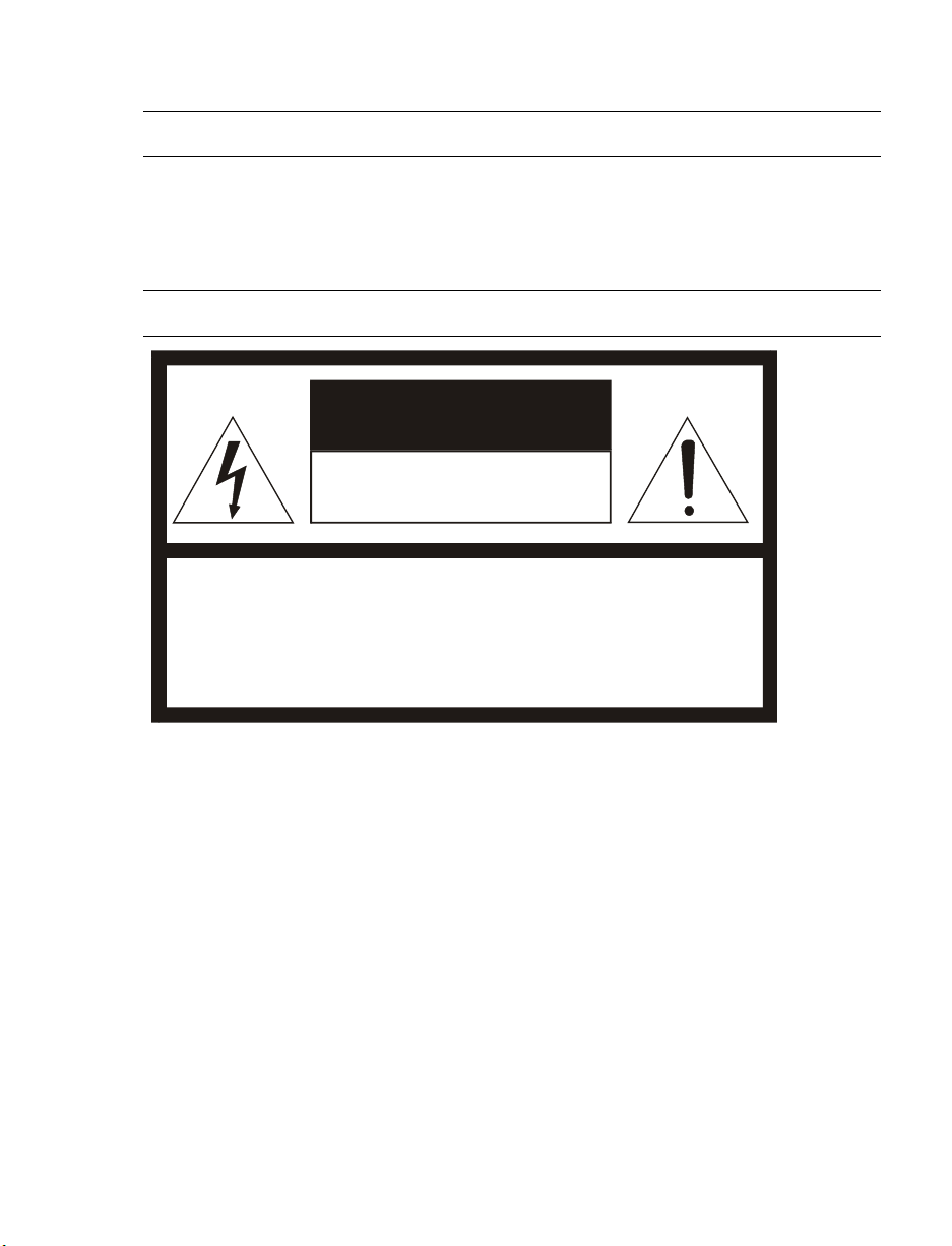
CAUTION: TO REDUCE THE RISK OF ELECTRIC SHOCK,
DO NOT REMOVE COVER (OR BACK).
NO USER-SERVICEABLE PARTS INSIDE.
REFER SERVICI NG TO QUA LIF IED SERVICE PERSONNEL.
CAUTION
RISK OF ELECTRI C SHOCK
DO NOT OPEN
Warning
DANGEROUS HIGH VOLTAGES ARE PRESENT INSIDE THE ENCLOSURE.
DO NOT OPEN THE CABINET.
REFER SERVICING TO QUALIFIED PERSONNEL ONLY.
Caution
6
Page 7

Standard Warranty
OpenEye warrants all new products to be free from defects in workmanship and material
under normal use for a period of two years after the date of purchase. Any defective
product that falls under this warranty will, at OpenEye's discretion, be repaired or replaced
at no additional charge. OpenEye may elect to replace defective products with new or
factory reconditioned products of equal or greater value. Repairs made necessary by
reason of misuse, alteration, normal wear, or accident are not covered under this
warranty.
Exceptions to this are listed below:
• Three Years on all Digital Recorders
• Three years on all fixed cameras
All products shall be covered by a one year advance replacement warranty*.
OpenEye will warrant all otherwise out of warranty replacement parts and repairs for 90
days from the date of OpenEye shipment.
The above warranty is the sole warranty made by OpenEye and is in lieu of all other
warranties by OpenEye express and implied, including without limitation the warranties of
merchantability and fitness for a particular purpose. Under no circumstances will OpenEye
be liable for any consequential, incidental, special or exemplary damages arising out of or
connected with the sale, delivery, use or performance of the product, even if OpenEye is
apprised of the likelihood of such damages occurring. In no event shall OpenEye liability
exceed the purchase price of the product.
This warranty gives you specific legal rights and you may also have other rights which
vary from state to state or country to country.
*Requires corresponding security deposit. Advanced Replacement limited to components
only outside of the USA and Canada.
For the most up to date information visit www.openeye.net
30104AD 7
Page 8

TABLE OF CONTENTS
Introduction ................................................................................................................................... 11
Overview .................................................................................................................................... 11
Product Features ................................................................................................................... 11
Getting Started .............................................................................................................................. 12
Box Contents .............................................................................................................................. 12
Camera Overview ....................................................................................................................... 13
Dimensions ............................................................................................................................ 13
Connections ........................................................................................................................... 14
Installation ..................................................................................................................................... 15
Power and Ethernet Connection ................................................................................................. 15
Power Connection .................................................................................................................. 15
Ethernet Cable Connection .................................................................................................... 15
Ceiling Installation ...................................................................................................................... 16
4S Electrical Box Installation ...................................................................................................... 22
Locate Camera ............................................................................................................................... 25
OpenEye Network Camera manager .......................................................................................... 25
Installation .............................................................................................................................. 25
Starting Network Camera Manager ........................................................................................ 25
Device Addressing ................................................................................................................. 26
Finding Network Devices .................................................................................................. 26
Setup & Configuration .................................................................................................................. 27
Connecting to the Camera .......................................................................................................... 27
Resetting the Camera ............................................................................................................ 27
Administrator/User Privileges ................................................................................................. 27
Connecting a Stream ............................................................................................................. 28
Connecting Over the Internet ................................................................................................. 29
Viewer Software ......................................................................................................................... 30
Viewer Tabs ........................................................................................................................... 30
Home ..................................................................................................................................... 31
System ................................................................................................................................... 32
System .............................................................................................................................. 32
Security ............................................................................................................................. 33
8
Page 9

Admin Password .......................................................................................................... 33
Add User ...................................................................................................................... 34
Delete user ................................................................................................................... 34
Edit user ....................................................................................................................... 34
Network ............................................................................................................................. 35
Get IP address automatically (DHCP) .......................................................................... 35
Use fixed IP address .................................................................................................... 35
DDNS ................................................................................................................................ 37
Mail ................................................................................................................................... 38
FTP ................................................................................................................................... 39
Application ........................................................................................................................ 40
Motion Detection ............................................................................................................... 42
Storage Management ........................................................................................................ 46
Recording .......................................................................................................................... 47
Snapshot ........................................................................................................................... 48
View Log File..................................................................................................................... 49
View User Information ....................................................................................................... 50
View User Login Information ........................................................................................ 50
View User Privilege ...................................................................................................... 50
View Parameters ............................................................................................................... 51
Factory Default .................................................................................................................. 52
Set Default ................................................................................................................... 52
Reboot .......................................................................................................................... 52
Software Version ............................................................................................................... 53
Software Upgrade ............................................................................................................. 54
Upgrading the Camera Viewer Software ...................................................................... 54
Maintenance...................................................................................................................... 56
Video and Audio Streaming Settings ..................................................................................... 57
Video Format..................................................................................................................... 57
Text Overly Settings ..................................................................................................... 57
Video Rotate Type........................................................................................................ 58
Video Compression ........................................................................................................... 59
Video OCX Protocol .......................................................................................................... 60
Multicast Mode ............................................................................................................. 60
Video Frame Skip .............................................................................................................. 61
Video Mask ....................................................................................................................... 62
Audio ................................................................................................................................. 63
Transmission Mode ...................................................................................................... 63
30104AD 9
Page 10

Bit Rate ........................................................................................................................ 64
Camera .................................................................................................................................. 65
Exposure ........................................................................................................................... 65
White Balance ................................................................................................................... 66
Brightness ......................................................................................................................... 66
Sharpness ......................................................................................................................... 66
Contrast ............................................................................................................................ 66
Saturation .......................................................................................................................... 67
Digital Zoom ...................................................................................................................... 67
IR Function ........................................................................................................................ 67
WDR Function ................................................................................................................... 67
3DNR ................................................................................................................................ 67
TV System ........................................................................................................................ 67
Logout .................................................................................................................................... 67
Specifications ................................................................................................................................ 68
Camera Specifications ................................................................................................................ 68
IP Specifications ......................................................................................................................... 69
10
Page 11

INTRODUCTION
OVERVIEW
The CM-730 is an outdoor IP Dome, capable of providing real-time high-quality video. The
CM-730 is capable of dual streaming, delivering multiple streams to multiple clients with
options for streaming in MJPEG, MPEG4 and H.264.
With a compact and sophisticated mechanical design the Outdoor IP Dome Camera is
easy to install and the vandal proof cover can protect the camera from heavy damage.
Product Features
• Sony Progressive CCD
• H.264/ MPEG-4/ MJPEG video streaming
• Resolution: 1280 x 960, HD 720p, D1, VGA, QVGA, CIF, QCIF
• Frame Rate: all resolutions transmit 25/30ips real time
• Image Settings:
Rotation: Flip, Mirror, and 180° Rotate
Brightness, Sharpness, Contrast, White Balance, Exposure Control
Digital Zoom: x1 ~ x16
• Built-in WDR, 2D/3D Noise Reduction, ICR
• Two-way audio support
• Weatherproof (IP66 international standard)
• Security Torx screws protect against tampering
• 3-axis (pan/tilt/rotation) position adjustment
• Built-in heater and fan
• 4S mount support
30104AD 11
Page 12

GETTING STARTED
BOX CONTENTS
Before proceeding, please check that the box contains the items listed here. If any item is
missing or has defects, DO NOT install or operate the product and contact your dealer for
assistance.
CM-730 Camera Power Cable
12
Self Tapping Screws Plastic Anchors Security Torx Tool
Rubber Washers Quick Start Guide CD
Page 13

CAMERA OVERVIEW
Before installing or connecting the dome camera, please refer to this section and complete
preparations for dome setup and all switch settings.
Dimensions
• Diameter – 151 mm (5.9 inches)
• Height – 130 mm (5.12 inches)
30104AD 13
Page 14

Connections
Item Pin Definition
Reset - Restore Factory Default Settings
BNC - Analog Video Output
Alarm I/O 1 Alarm Output
2 Alarm Output
3 Alarm Input
4 Alarm Input
14
Audio I/O 1 Input
2 GND
3 Output (R)
4 Output (L)
RJ45 - 10/100 Ethernet PoE
Power 12vDV / 24vAC 1 Power (+)
2 GND
3 Power (-)
Page 15

INSTALLATION
POWER AND ETHERNET CONNECTION
Read the installation instructions before installing and connecting the IP camera.
Power Connection
You can use 12vDC power, 24vAC power or Power over Ethernet (PoE) to power the CM730 camera. When powered by PoE, any 802.3af compliant device may be used to
provide power. When using 12vDC or 24vAC power, refer to the pin definition table in the
Camera Overview > Connections section for the proper 2-wire connection.
Note OpenEye recommends against using more than one power source at a time. Do
not use a PoE power source when providing the camera with 12vDC or 24vAC
power.
However, only 24vAC power will properly power the heater in the camera. If the camera is
not subjected to temperatures lower than 40°F, a heater is not necessary and 24vAC,
12vDC or PoE (using an injector or compliant switch) will be suitable. Please verify that all
installations that require a heater use 24vAC power.
Make sure the camera’s power cable is correctly and firmly connected. If using Power
over Ethernet (PoE), make sure Power Sourcing Equipment (PSE) is in use in the
network.
Ethernet Cable Connection
OpenEye recommends using Category 5 Ethernet cable to connect the camera to your
network. For the best transmission quality, the cable length should not exceed 328 feet
(100 meters). Connect a network cable to the camera using t he RJ45 input and connect
the other end of the cable to your network switch or DVR.
Note If you are connecting the camera directly to a DVR, a crossover cable is
necessary for most configurations.
Check the status of the network connection by looking at the link indicator and activity
indicator LEDs. If the LEDs are not lit check your network connection. The green link LED
indicates a network connection and the orange activity LED flashes to indicate network
activity.
30104AD 15
Page 16

CEILING INSTALLATION
You can install your CM-730 directly onto a wall or ceiling. The wall or ceiling must have
enough strength to support the IP Dome Camera.
1. Use the supplied Torx tool to unscrew the two Torx screws on the side of the dome
cover and remove the dome cover.
2. Press both sides of the Inner Cover and remove it from the Dome Camera.
16
Page 17

3. Unscrew the Torx screw on the camera module, as indicated in the figure, with the
supplied Torx tool.
4. Press the sides of the snap-on module, as indicated in the figure, and detach it from
the Dome Camera’s housing.
5. Mark the positions of the four screw holes on the base of the Dome Camera at the
chosen installation location.
6. In the marked locations, drill each hole slightly smaller than the supplied screw
anchors.
7. Insert the supplied anchors into the drilled holes.
30104AD 17
Page 18

8. Fasten the camera housing to the ceiling with the supplies screws
9. Thread the power and Ethernet cables through the side conduit entry or the back
conduit entry.
Note The power cable is omitted if using PoE.
10. Connect the power and Ethernet connectors on the camera with their respective
cables.
18
Page 19

11. Attach the snap-on module to the camera housing, and scr ew the module screw
tightly with the Security Torx to secure the camera module.
Note The terminal blocks should face the side conduit entry, as shown in the figure.
12. Use the OpenEye IP Finder software to locate the camera on the network and
complete configuration of the camera.
13. After connecting to the camera, adjust the camera's zoom level and focal length using
the zoom and focus ring screws.
30104AD 19
Page 20

14. Adjust the camera to the desired angle. Pan adjust ment range is nearly 360°; rotation
angle range approaches to 270°. Tilt is adjustable between ﹣10° ~ 90°.
Pan Adjustment Rotation Adjustment Tilt Adjustment
Note Adjust the lens carefully within the limits mentioned above, or the cables
underneath will be damaged.
15. Replace the Inner Dome cover.
20
Page 21

16. Replace the dome cover, aligning the arrow mark on the dome cover with the one on
the housing.
17. Screw the two Torx screws on the side of the dome cover tightly to fasten the dome
cover.
30104AD 21
Page 22

4S ELECTRICAL BOX INSTALLATION
Before installing the camera in a 4S Electrical Box, unscrew and open the dome cover
with the Security Torx.
1. Run the wires (Ethernet and p ower) through the wall to the 4S box.
Note The Power Cable is omitted if using PoE.
2. Press both sides of the Inner Cover and remove it from the Dome Camera.
22
Page 23

3. Unscrew the Torx screw on the camera module, as indicated in the figure, with the
supplied Torx tool.
4. Press the sides of the snap-on module, as indicated in the figure, and detach it from
the Dome Camera’s housing.
30104AD 23
Page 24

5. Thread the power and Ethernet cables through either the side conduit entry or back
conduit entry. Then fasten the Dome Camera’s housing to the Electrical Box with the
two screws.
6. Connect the power and Ethernet cables to their connectors on the Dome Camera
unit.
7. Attach the snap-on module to the camera housing, and screw the module screw
tightly with the Security Torx to secure the camera module.
8. Use the OpenEye IP Finder software to locate the camera on the network and
complete configuration of the camera.
9. After connecting to the camera, adjust the camera's zoom level and focal length using
the zoom and focus ring screws.
10. Replace the inner dome cover.
11. Replace the dome cover, aligning the arrow mark on the dome cover with the one on
the housing.
12. Screw the two Torx screws on the side of the dome cover tightly to fasten the dome
cover.
24
Page 25

LOCATE CAMERA
OPENEYE NETWORK CAMERA MANAGER
Use the included Network Camera Manager software to easily find your network cameras
for initial setup. The OpenEye IP Finder software is included on the CD with all OpenEye
IP devices.
Installation
You can install Network Camera Manager on any personal computer (PC) or laptop using
the software CD included with your OpenEye IP camera or by downloading the program
from openeye.net.
Note Network Camera Manager will only work on PCs or laptops that use a Windows
operating system. It is compatible with Windows XP, Vista, 7, and 8.
Starting Network Camera Manager
After installing the program on your PC or laptop, open the program to begin configuring
your cameras.
To access Network Camera Manager on an OpenEye recorder, you must operate the
recorder in Windows Mode.
1. In the Live Screen, click Exit.
2. Click Restart in Windows Mode.
3. Click OK.
4. Double-click Network Camera Manager.
30104AD 25
Page 26

Device Addressing
The functions on the Device Addressing tab allow you to find, configure, and view network
cameras.
Finding Network Devices
5. Click Find Devices on the Device Addressing tab.
6. To narrow your search by Camera Model, Project, or Camera Name, select
your desired criteria from the appropriate lists.
26
Page 27

SETUP & CONFIGURATION
CONNECTING TO THE CAMERA
1. Locate the camera on the IP Finder list.
2. Double-click the camera to open the Viewer software in your web browser.
3. Log in to the camera with the appropriat e User Name and Password.
Note The default User name is Admin and the default Password is1234. The
username and password are case sensitive. OpenEye recommends you change
the Admin password for security reasons.
Resetting the Camera
If it is necessary to reset the camera to the factory default settings, hold down the Reset
button (see Connections) for 30 seconds. This will return all settings, inc lud ing network
setup, to the factory default. The IP address of the camera will return to 192.168.0.250.
Administrator/User Privileges
The Administrator account has the authority to configure the IP camera and authorize
users’ access to the camera. The User accounts have access to the camera with limited
authority.
30104AD 27
Page 28

Connecting a Stream
OpenEye IP cameras are optimized for use with OpenEye recorders, but you can also
connect to your OpenEye IP cameras using third party software like VLC media player
(http://www.videolan.org).
To connect the camera you may need to provide the stream URL. All OpenEye IP
cameras are capable of delivering two RTSP streams, as well as streaming MJPEG over
HTTP. The stream URLs are listed below.
rtsp://<ip address>/mjpeg
rtsp://<ip address>/mpeg4
rtsp://<ipaddress>/h264
http://<ipaddress>:8008
The MJPEG over HTTP stream is identified by a port number. The default port is 8008;
this port can be configured in the cameras Network page:
28
 Loading...