

Page 1
Outdoor Speed Dome Camera
User Manual
Camera
CM-511
Accessories
CA-510G
CA-510W
CA-510C
CA-510P25
CA-510P50
CA-510PML
CA-510PMS
CA-510PA25
CA-510PA50
www.openeye.net
Page 2

ii
Page 3

CM-511 Outdoor Speed Dome Camera
User Manual
Manual Edition 29246AC – APRIL 2010
©2000-2010, OPENEYE
All Rights Reserved.
No part of this documentation may be reproduced in any means, electronic or mechanical, for any
purpose, except as expressed in the Software License Agreement. OpenEye shall not be liable for
technical or editorial errors or omissions contained herein. The information in this document is subject
to change without notice.
THE INFORMATION IN THIS PUBLICATION IS PROVIDED “AS IS” WITHOUT WARRANTY OF ANY KIND.
THE ENTIRE RISK ARISING OUT OF THE USE OF THIS INFORMATION REMAINS WITH RECIPIENT. IN
NO EVENT SHALL OPENEYE BE LIABLE FOR ANY DIRECT, CONSEQUENTIAL, INCIDENTAL, SPECIAL,
PUNITIVE, OR OTHER DAMAGES WHATSOEVER (INCLUDING WITHOUT LIMITATION, DAMAGES FOR
LOSS OF BUSINESS PROFITS, BUSINESS INTERRUPTION OR LOSS OF BUSINESS INFORMATION),
EVEN IF OPENEYE HAS BEEN ADVISED OF THE POSSIBILITY OF SUCH DAMAGES AND WHETHER IN
AN ACTION OR CONTRACT OR TORT, INCLUDING NEGLIGENCE.
This documentation is copyrighted. All other rights are reserved to OPENEYE. OPENEYE, and
OpenEye, are registered trademarks of OPENEYE in the United States and elsewhere; Windows,
and Windows XP Embedded are registered trademarks of Microsoft Corporation. All other brand and
product names are trademarks or registered trademarks of the respective owners.
OPENEYE
Liberty Lake, WA ● U.S.A.
29246AC iii
Page 4

Important Safeguards
1. Read Instructions
Read all of the safety and operating instructions before using the product.
Retain Instructions
2.
Save these instructions for future reference.
Attachments / Accessories
3.
Do not use attachments or accessories unless recommended by the appliance manufacturer as they may cause
hazards, damage product and void warranty.
4. Installation
Do not place or mount this product in or on an unstable or improperly supported location. Improperly installed
product may fall, causing serious injury to a child or adult, and damage to the product. Use only with a mounting
device recommended by the manufacturer, or sold with the product. To insure proper mounting, follow the
manufacturer's instructions and use only mounting accessories recommended by manufacturer.
Power source
5.
This product should be operated only from the type of power source indicated on the marking label.
Precautions
Operating
z Before using, make sure power supply and others are properly connected.
z While operating, if any abnormal condition or malfunction is observed, stop using the camera
immediately and then contact your local dealer.
Handling
z Do not disassemble or tamper with parts inside the camera.
z Do not drop or subject the camera to shock and vibration as this can damage camera.
z Do not block the cooling holes on the bracket. This camera has a cooling fan inside the housing.
Blocking the cooling holes will cause heat to build up and cause malfunction.
z Care must be taken when you clean the clear dome cover. Scratches and dust will ruin the image
quality of your camera. Do not use strong or abrasive detergents when cleaning the camera body.
Use a dry cloth to clean the camera when it is dirty. In case the dirt is hard to remove, use a mild
detergent and wipe the camera gently.
iv
Page 5
Installation and Storage
z Do not install the camera in areas of extreme temperatures in excess of the allowable range. (-
50°C ~50°C / -58°F ~ 122°F)
z Avoid installing in humid or dusty places. The relative humidity must be below 90%.
z Avoid installing in places where radiation is present.
z Avoid installing in places where there are strong magnetic fields and electric signals.
z Avoid installing in places where the camera would be subject to strong vibrations.
Never face the camera toward the sun. Do not aim at bright objects. Whether the camera is in use or not,
never aim it at the sun or other extremely bright objects. Otherwise the camera may be smeared and
damaged.
Regulation
This device complies with Part 15 of the FCC Rules. Operation is subject to the following two conditions: (1) this
device may not cause harmful interference, and (2) this device must accept any interference received, including
interference that may cause undesired operation.
This symbol on the product or on its packaging indicates that this product shall not be
treated as household waste in accordance with Directive 2002/96/EC. Instead it shall be
handed over to the applicable collection point for the recycling of electrical and electronic
equipment. By proper waste handling of this product you ensure that it has no negative
consequences for the environment and human health, which could otherwise be caused if
this product is thrown into the garbage bin. The recycling of materials will help to
conserve natural resources.
For more details information about recycling of this product, please contact your local city
office, your household waste disposal service or the shop where you purchased the
product.
Compliance is evidenced by written declaration from our suppliers, assuring that any
potential trace contamination levels of restricted substances are below the maximum
level set by EU Directive 2002/95/EC, or are exempted due to their application.
29246AC v
Page 6
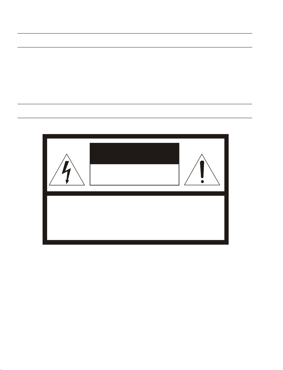
Warning
DANGEROUS HIGH VOLTAGES ARE PRESENT INSIDE THE ENCLOSURE.
DO NOT OPEN THE CABINET.
REFER SERVICING TO QUALIFIED PERSONNEL ONLY.
Caution
CAUTION
RISK OF ELECTRIC SHOCK
DO NOT OPEN
CAUTION: TO REDUCE THE RISK OF ELECTRIC SHOCK,
DO NOT REMOVE COVER (OR BACK).
NO USER-SERVICEABLE PARTS INSIDE.
REFER SERVICING TO QUALIFIED SERVICE PERSONNEL.
vi
Page 7

Standard Warranty
OpenEye warrants all new products to be free from defects in workmanship and material under normal use for a
period of two years after the date of purchase. Any defective product that falls under this warranty will, at OpenEye's
discretion, be repaired or replaced at no additional charge. OpenEye may elect to replace defective products with new
or factory reconditioned products of equal or greater value. Repairs made necessary by reason of misuse, alteration,
normal wear, or accident are not covered under this warranty.
Exceptions to this are listed below:
• Three Years on all Digital Recorders
• Three years on all fixed cameras
All products shall be covered by a one year advance replacement warranty*.
OpenEye will warrant all otherwise out of warranty replacement parts and repairs for 90 days from the date of
OpenEye shipment.
The above warranty is the sole warranty made by OpenEye and is in lieu of all other warranties by OpenEye express
and implied, including without limitation the warranties of merchantability and fitness for a particular purpose. Under
no circumstances will OpenEye be liable for any consequential, incidental, special or exemplary damages arising out
of or connected with the sale, delivery, use or performance of the product, even if OpenEye is apprised of the
likelihood of such damages occurring. In no event shall OpenEye liability exceed the purchase price of the product.
This warranty gives you specific legal rights and you may also have other rights which vary from state to state or
country to country.
*Requires corresponding security deposit. Advanced Replacement limited to components only outside of the USA and
Canada.
For the most up to date information visit www.openeye.net
29246AC vii
Page 8

NOTES:
viii
Page 9

Table of Contents
INTRODUCTION ........................................................................... 11
OVERVIEW ..................................................................................................... 11
Product Features ......................................................................................... 11
GENERAL OPERATION REQUIREMENTS ................................................... 12
System Configuration .................................................................................. 12
GETTING STARTED..................................................................... 13
CAMERA CONTENTS .................................................................................... 13
CAMERA SETTINGS ...................................................................................... 15
Switch /Connector Definition ....................................................................... 15
Communication Switch Setting ................................................................... 16
Dome ID Setting .......................................................................................... 16
Dome Control Protocol Setting ................................................................... 17
All-in-one Data Cable .................................................................................. 18
RS-485 Connector Definition .................................................................. 18
22-Pin Connector Definition .................................................................... 19
OPERATION & CONFIGURATION .............................................. 20
OSD FORMAT ................................................................................................ 20
OSD MENU TREE .......................................................................................... 21
CONFIGURATION MENU ............................................................................... 25
Entering the OSD Menu .............................................................................. 25
Selecting a Setup Item on the OSD Menu .................................................. 25
Setting up an OSD item .............................................................................. 25
Language .................................................................................................... 26
Changing the Display Language ............................................................ 26
Default Camera Settings ............................................................................. 26
Backlight ...................................................................................................... 26
Focus ........................................................................................................... 27
AE Mode...................................................................................................... 27
WBC (White Balance Control) Mode .......................................................... 28
Image Ctrl .................................................................................................... 29
Zoom Speed ........................................................................................... 29
Digital Zoom ............................................................................................ 29
Slow Shutter ........................................................................................... 29
D.N.R. ..................................................................................................... 29
Image Inverse ......................................................................................... 30
Freeze ..................................................................................................... 30
Aperture .................................................................................................. 30
29246AC ix
Page 10

Exit .......................................................................................................... 30
Telemetry Ctrl.............................................................................................. 31
Flip .......................................................................................................... 31
Angle Adjuster ........................................................................................ 31
Speed by Zoom ...................................................................................... 32
Auto Cali. (Auto Calibration) ................................................................... 32
System Reset ......................................................................................... 32
Exit .......................................................................................................... 32
ID Display .................................................................................................... 32
Title Display................................................................................................. 33
Title Setting ................................................................................................. 33
Setting a Camera Title ............................................................................ 33
Preset .......................................................................................................... 34
Setting Preset Points .............................................................................. 34
Running a Preset .................................................................................... 34
Exit the Preset Menu .............................................................................. 34
Tour ............................................................................................................. 35
Autoscan ..................................................................................................... 36
Pattern ......................................................................................................... 38
Home Setting .............................................................................................. 39
IR Function (Removable IR Cut) ................................................................. 40
Alarm Setting............................................................................................... 41
WIDE DYNAMIC RANGE (WDR) ............................................................... 43
Privacy Mask ............................................................................................... 43
Time Setting ................................................................................................ 45
Schedule ..................................................................................................... 46
Exit OSD ..................................................................................................... 47
HOT KEY COMMANDS .................................................................................. 47
SPECIFICATIONS ........................................................................ 48
CAMERA SPECIFICATIONS .......................................................................... 48
PTZ SPECIFICATIONS .................................................................................. 49
OSD MENU NOTES ....................................................................................... 50
x
Page 11

INTRODUCTION
OVERVIEW
With a weather resistant feature, the Integrated High Speed Dome Camera is applicable to outdoor installations.
The dome camera supports all-in-one cabling for easy installation and can be integrated with CCTV products,
such as DVRs, Control Keyboards, and CCTV accessories for a total surveillance solution. In addition, a large
set of built-in protocols provides connectivity to other surveillance systems. The built-in protocols include OPTIX
3, Pelco, VCL, Philips, AD-422, etc.
PRODUCT FEATURES
Precise and Accurate Dome Performance
• Auto Calibration
• Preset accuracy of 0.225°
• Preset speed up to 400°/sec.
• Proportional Pan & Tilt Speed
• Preset Position / Tour / Auto Scan / Pattern
Dynamic Dome Applications
• Multi-language OSD
• Schedule function
• Multiple built-in Protocols
• Up to 16 masking zones
• 8 alarm inputs, 1 alarm output
• Flexible outdoor mountings
• Compact lightweight design for easy installation
• Weather resistant housing
Superior Camera Image Quality
• Minimum illumination 0.01 Lux (B/W)
• Digital Slow Shutter
• Electronic Shutter
• Auto White Balance
• Backlight Compensation
• Auto Exposure
• Image Inverse
• Automatic Removable IR Cut Filter
29246AC 11
Page 12
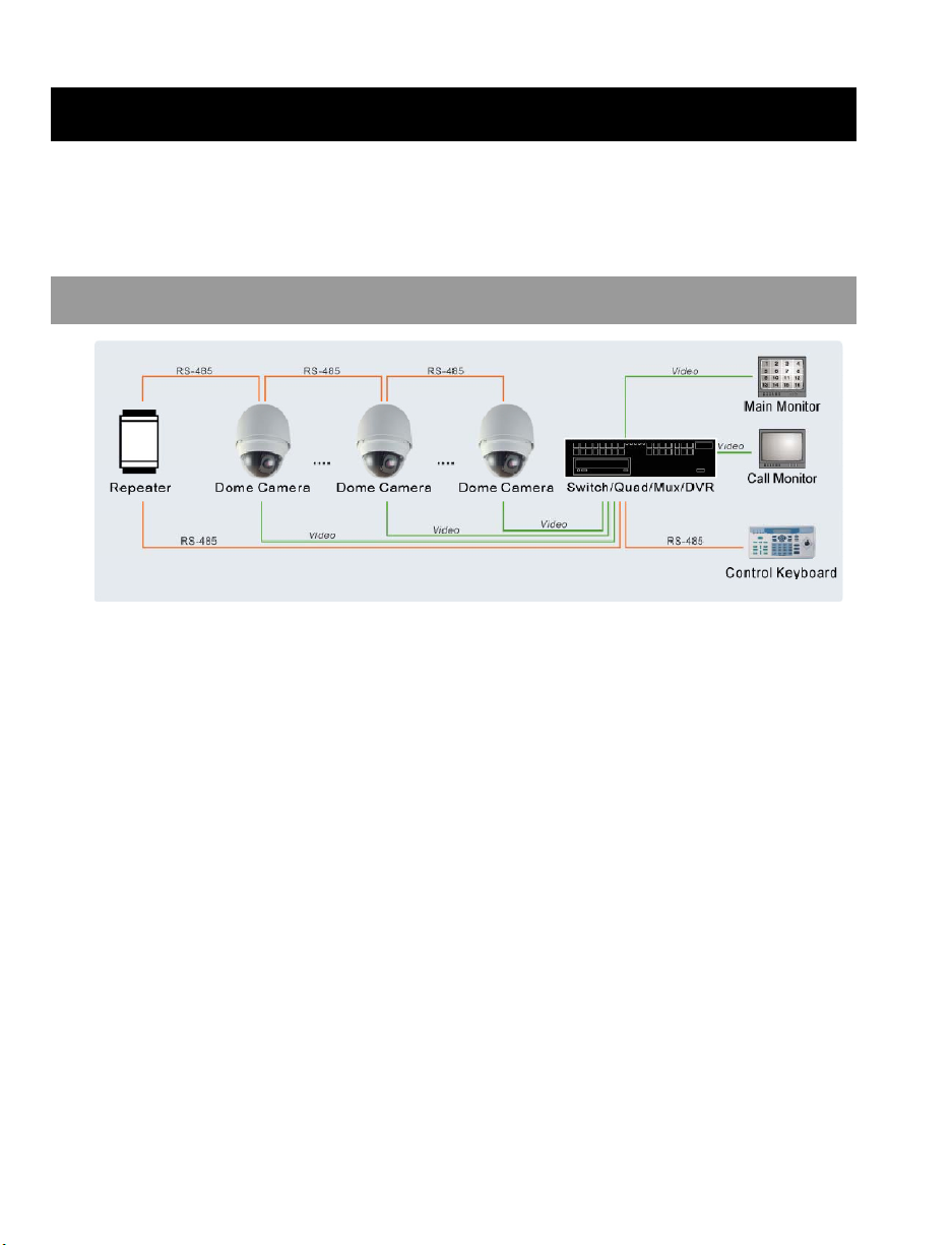
GENERAL OPERATION REQUIREMENTS
A minimum of one control device is required for operation, such as a control keyboard, or a DVR. The integrated
high speed dome camera contains a built-in receiver that decodes commands from a control device.
Connect dome cameras to other devices, as shown in the diagram below, to complete a video surveillance
system.
SYSTEM CONFIGURATION
Note To extend the network distance up to 1.2 km (4000 feet) and to protect the connected devices,
OpenEye recommends placing a repeater at the mid-point. However, a repeater may be needed with
network distances less than 1.2 km if the cables used are not CAT 5, 24-gauge cables. Refer to the
repeater’s manual for detailed information.
12
Page 13
GETTING STARTED
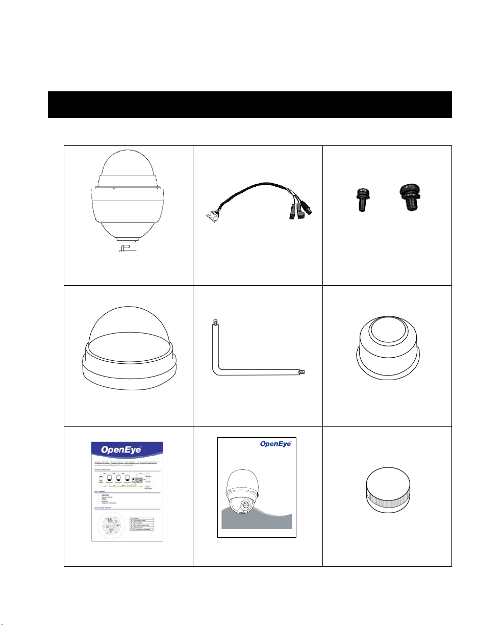
CAMERA CONTENTS
Before proceeding, please check that the box contains the items listed here. If any item is missing or has
defects, DO NOT install or operate the product and contact your dealer for assistance.
Dome Body
All-in-one Data Cable for power
supply, video and telemetry
Screws
Optical Cover Security Torx Tool Waterproof Gasket
510-Series Camera
Speed Dome
Installation Manual
model no.
model no.
CM-510
XM5000
Please carefully read these instructions before using this product.
Save this manual for future use.
Quick Start Guide Installation and User Manuals Lubricant
29246AC 13
Page 14

14
Page 15
CAMERA SETTINGS
r
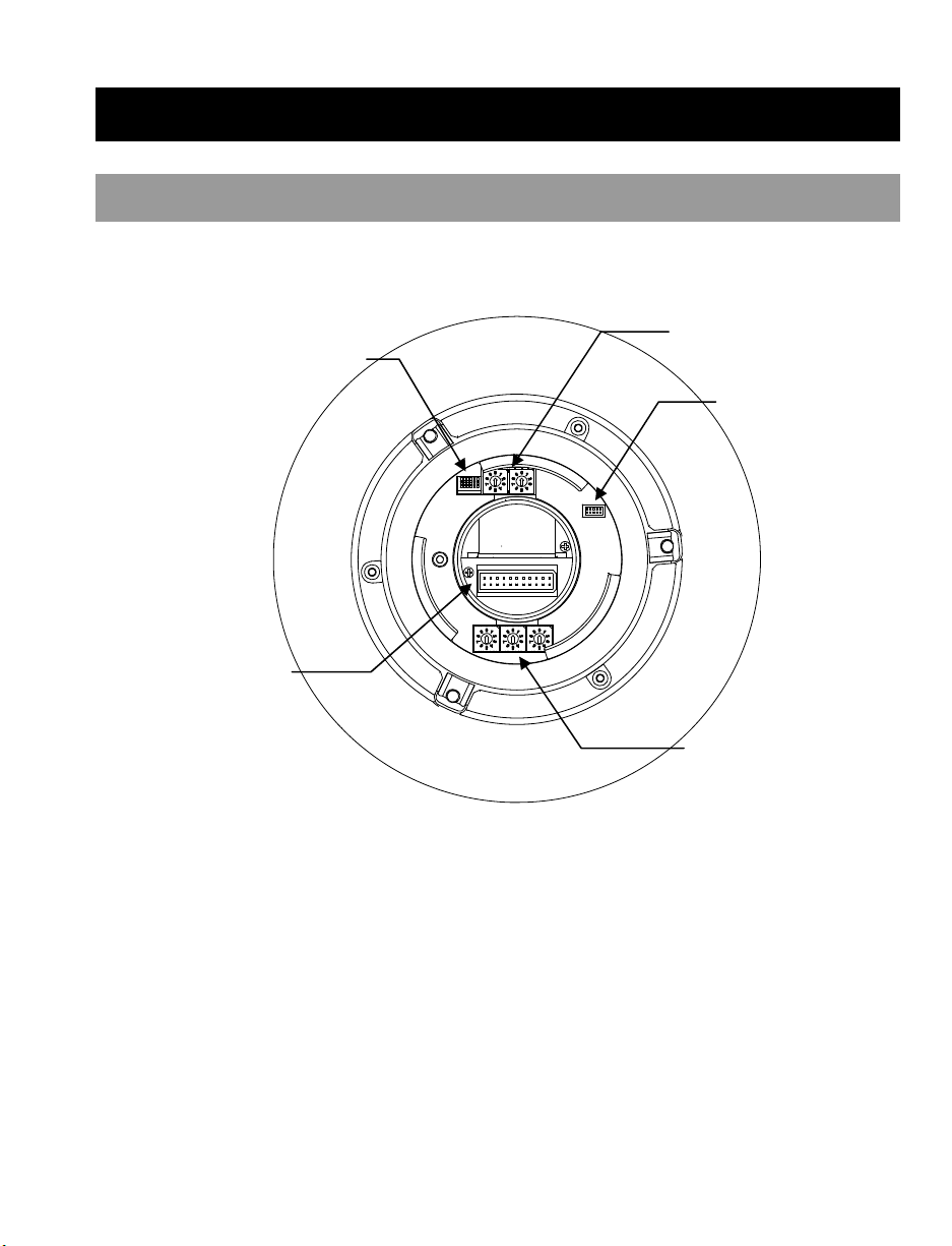
SWITCH /CONNECTOR DEFINITION
The dome ID and communication switch settings must be set before connecting the dome camera to other
CCTV devices. These switches are located on the bottom of the dome camera.
Communication
Switch
22-pin Connecto
Dome Control Protocol Switch
ISP Connector
(for firmware upgrade)
Dome ID Switch
29246AC 15
Page 16
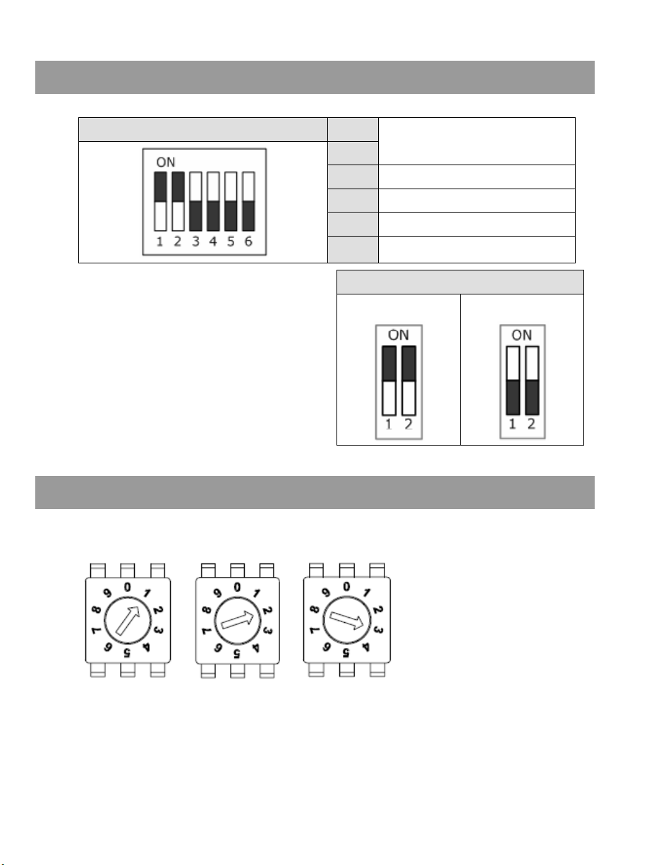
COMMUNICATION SWITCH SETTING
The table below shows the function of each switch with the Communication Switch.
RS-485 is the interface that the dome camera uses to
communicate with its control device; for this reason,
the RS-485 setup of the dome and the control device
must be the same. The RS-485 default setting is halfduplex (see the diagram right). Do not change the
default setting without a qualified specialist or
supplier’s notice. As for the SW 3 and SW 4, they are
used for termination and Line Lock adjustment
respectively. The SW 5 is mainly used when users
want to restore the camera to the factory default
status. Additionally, after a firmware upgrade is carried
out, users must reset the SW 5.
Communication Switch SW1
SW2
SW3 Termination
SW4 Line Lock
SW5 System Initialization
SW6
RS-485 Setting
Reserved
RS-485 Setting
Half-duplex Full -duplex
DOME ID SETTING
Use the switch to change your speed dome ID by turning the arrow to the desired number. For instance, if the
dome ID is 123, the ID switch should be set as below.
Centesimal Digit Decimal Digit Single Digit
Note No two domes should have the same ID, or communication conflict may occur
Note The number 0 should be at the top, as shown, when setting the camera ID.
16
Page 17
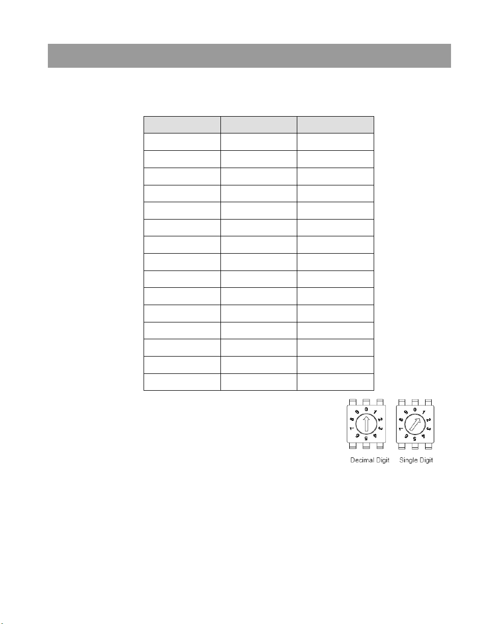
DOME CONTROL PROTOCOL SETTING
Define the protocol you are going to use based on the devices of your surveillance system. Generally, use one
protocol even if the devices are provided by different manufacturers. Use the switch to set your dome control
protocol and the baud rate. Refer to the table below and turn the arrow to choose a protocol for your speed
dome.
00 VCL 9600
01 Pelco D 2400
02 Pelco P 4800
04 Chiper 9600
05 Philips 9600
07 OPTIX 3 9600
08 AD422 4800
09 DM P 9600
11 Pelco D 4800
12 Pelco D 9600
13 Pelco P 2400
14 Pelco P 9600
15 JVC 9600
21 Kalatel-485 9600
22 Kalatel-422 4800
Example To set the protocol Pelco D, with switch no. 1 and baud rate 2400,
the protocol switch should be set as at right.
Note The number 0 should be at the top, as shown, when setting the
camera ID.
Switch No. Protocol Baud Rate
29246AC 17
Page 18

ALL-IN-ONE DATA CABLE
Note Be careful not to pull the cables improperly during installation. OpenEye suggests that you fasten the
cables after installation is complete.
Note When wiring the power cable, make sure the Ground wire is inserted into the mid-pin of the terminal
block.
RS-485 Connector Definition
The dome camera uses the RS-485 interface to communicate with a connected control device. Connect a
control keyboard to the speed dome using the terminal block. OpenEye recommends using CAT 5 cables for
RS-485 communication with a maximum length of 4000 feet (1219 meters) for 24-gauge wire. If the total cable
length exceeds 4000 feet, use a repeater to maintain the signals. Refer to the table below for pin definition and
wiring.
1 7,10 T+, R+ (D+)
2~4 Reserved
5 8,9 T-, R- (D-)
Pin
Corresponding Pins
(22-Pin Connector)
Definition
18
Page 19

22-Pin Connector Definition
Using the 22-pin connector, installers can connect the power, video, and
RS-485 cables in one place. The alarm pins are serviceable for
connecting alarm input and output devices such as sensors, sirens, or
flashing lights to the surveillance system. For the definition of each pin,
refer to the list below.
Pin Definition Cable
1
AC 24-1/DC (+)
20AWG/18AWG
2 ALM NC
3
AC 24-2/DC (-)
20AWG/18AWG
4 ALM NO
5 FG 20AWG/18AWG
6 ALM COM
7 T+
8 R-
24AWG
9 T-
10 R+
11 ISOG
12 ALM-1
13 ALM-3
14 ALM-2
15 ALM-4
16 ALM-5
17 ALM-6
18 ALM-7
19 ALM-8
20 ALM GND
21 VGND
20AWG
22 Video
Note For alarm connections, refer to the Cable Wiring and Connection section.
29246AC 19
Page 20

OPERATION & CONFIGURATION
OSD FORMAT
The information displayed on the screen is described in terms of
OSD, position and function description in the table below.
Position Function OSD Display Description
1 Motion MOTION Alarm Detect Message
2 Alarm ALARM 1 Alarm Message
M Manual Focus Mode
X Backlight Compensation OFF
B Backlight Compensation ON
8 Camera ID 001 Show the camera ID
9 Time XXXX/XX/XX XX:XX Year/Month/Day Hour:Minute
3
4 Booting Message
5 Error Message
6 Zoom Ratio X1
7 Title
Focus Modes &
Backlight
• Maximum 20 characters for each title
• 16 sets of titles are available
A Auto Focus Mode
XX (Dome Type)
ID:001 (Default)
DSCP/9600 (Default)
Initializing
PAN ERROR
TILT ERROR
CAM MODULE ERROR
Shows Dome Type, ID Address,
Protocol and Baud Rate
Shows system initializing error
(Optical Zoom/Digital Zoom)
message
Present Zoom Ratio
20
Page 21

OSD MENU TREE
The OSD setup menu structure of the 511 dome camera is listed below. The star symbol indicates the factory
default. For detailed function descriptions, see Configuration Menu.ON
Item Layer 1 Layer 2 Layer 3 Default
LANGUAGE
DEFAULT
CAMERA
BACKLIGHT
FOCUS
AE MODE
WBC MODE
<ENGLISH>, <JAPANESE>, <PORTUGUESE>, <SPANISH>, <FRENCH>, <GERMAN>,
<ITALIAN>, <POLISH>, <RUSSIAN>, <TRADITIONAL CHINESE>,<SIMPLIFIED CHINESE>,
ENGLISH
<TURKISH>
<ON>, <OFF>
<ON> BLC LEVEL <00> ~ <30>
<OFF>
ON
OFF
AUTO AF MODE <NORMAL>, <Z. TRIG.>, <PT TRIG.> NORMAL
MANUAL
EXPOSURE
COMP.
<OFF>, EXPOSURE VALUE: <-10.5dB> ~ <10.5dB> OFF
AUTO
BRIGHT VALUE; SHUTTER SPEED; IRIS VALUE; GAIN
VALUE: AUTO
☆
SHUTTER SHUTTER SPEED: <1/60> ~ <1/10000> SEC.
AE MODE
IRIS IRIS VALUE <F1.6>
BRIGHT VALUE: AUTO
MANUAL
SHUTTER SPEED: <1/60> ~ <1/10000> SEC.
GAIN VALUE <-3> dB ~ <28>dB
EXIT+SAVE YES
AUTO (Auto White Balance)
☆
INDOOR
OUTDOOR
MANUAL
R GAIN <000> ~ <127>
B GAIN <000> ~ <127>
29246AC 21
Page 22

Item Layer 1 Layer 2 Layer 3 Default
ZOOM SPEED <1> ~<8> 8
DIGITAL ZOOM <OFF>, <2x> ~ <12x> OFF
SLOW SHUTTER <ON>, <OFF> OFF
2D N.R. <ON>, <OFF>
3D N.R. <ON>, <OFF>
OFF
IMAGE CTRL
D.N.R.
IMAGE INVERSE <ON>, <OFF> OFF
FREEZE <ON>, <OFF> OFF
APERTURE <01> ~ <16> 07
EXIT YES
FLIP <OFF>, <M.E.>, <IMAGE> OFF
ANGLE ADJUSTER
MIN ANGLE <-10 ~ +10 DEG>
MAX ANGLE <080 ~ 100 DEG>
0
90
SPEED BY ZOOM <ON>, <OFF> OFF
TELEMETRY
CTRL
AUTO CALIBRATE <ON>, <OFF> OFF
PASSWORD <ON>, <OFF>
OSD AUTO CLOSE <OFF>, <5> ~ <30> SEC.
SYSTEM RESET
SYSTEM RESET <YES>
DEFAULT SYSTEM <YES>
EXIT YES
ID DISPLAY <ON>, <OFF>
TITLE
DISPLAY
TITLE
SETTING
<ON>, <OFF>
<01> ~ <16>
ON
OFF
1
PRESET SET <001>~<256> 001
PRESET
PRESET RUN <001>~<256> 001
EXIT YES
TOUR LINE <1> ~ <8> 1
TOUR POINT <01> ~ <64> 1
PRESET POS. <001> ~ <255>, <END> END
TOUR
SPEED <01> ~ <15> 1
DWELL TIME <000> ~ <127> SEC. 0
RUN TOUR ENTER
EXIT YES
22
Page 23

Item Layer 1 Layer 2 Layer 3 Default
AUTOSCAN LINE <1> ~ <4> 1
START POINT <TO FIND>, <TO SAVE>
END POINT <TO FIND>, <TO SAVE>
AUTOSCAN
DIRECTION <RIGHT>, <LEFT> RIGHT
SPEED <01> ~ <04> 1
RUN AUTOSCAN ENTER
EXIT YES
PATTERN LINE <1> ~ <8> 1
RECORD START ENTER
PATTERN
RECORD END ENTER
RUN PATTERN ENTER
EXIT YES
HOME FUNCTION <ON>, <OFF> OFF
SELECT MODE <PRESET>, <TOUR>, <AUTOSCAN>, <PATTERN> PRESET
HOME
SETTING
PRESET POINT
TOUR LINE
AUTOSCAN LINE
PATTERN LINE
<001> ~ <256>
<1> ~ <8>
<1> ~ <4>
<1> ~ <8>
1
1
1
1
RETURN TIME <1> ~ <128> MIN. 1
GO ENTER
EXIT YES
IR FUNCTION
<AUTO> THRESHOLD <MID>, <HI>, <LOW>
<MANUAL> IR MANUAL: <ON, <OFF>
AUTO
ALARM PIN <1> ~ <8> 1
ALARM SWITCH <ON>, <OFF> OFF
ALARM TYPE <NO> (Normal Open), <NC> (Normal Close) NC
ALARM ACTION <PRESET>, <TOUR>, <AUTOSCAN>, <PATTERN> PRESET
ALARM
SETTING
PRESET POINT
TOUR LINE
AUTOSCAN LINE
PATTERN LINE
<001> ~ <256>
<1> ~ <8>
<1> ~ <4>
<1> ~ <8>
1
1
1
1
DWELL TIME <001> ~ <127> Sec., <ALWAYS> ALWAYS
EXIT YES
ALARM
DETECT
<NONE>
NONE
29246AC 23
Page 24

Item Layer 1 Layer 2 Layer 3 Default
WDR
FUNCTION
PRIVACY
MASK
TIME SETTING
SCHEDULE
EXIT OSD YES
<ON>, <OFF> ON
PRIVACY SWITCH <ON>, <OFF> OFF
TRANSPARENCY <ON>, <OFF> OFF
COLOR
SET MASK <01> ~ <16>
CLEAR MASK <01> ~ <16>
EXIT YES
TIME DISPLAY <ON>, <OFF> OFF
SET YEAR <00> ~ <99>
SET MONTH <01> ~ <12>
SET DAY <00> ~ <31>
SET HOUR <00> ~ <23>
SET MINUTE <00> ~ <59>
EXIT+SAVE
SWITCH <ON>, <OFF> OFF
POINT <01> ~ <32> 1
HOUR <00> ~ <23> 0
MINUTE <00> ~ <59> 0
MODE
SCHEDULE RESET YES
EXIT YES
<BLACK>, <WHITE>,<RED>, <GREEN>, <BLUE>, <CYAN>,
<YELLOW>, <MAGENTA>
H CENTER: L/R
V CENTER: D/U
H SIZE <000> ~ <080>
V SIZE <000> ~ <080>
EXIT + SAVE
NONE NO FUNCTION
PRESET
TOUR TOUR LINE <1> ~ <8>
AUTOSCAN AUTOSCAN LINE <1> ~ <4>
PATTERN PATTERN LINE <1> ~ <8>
IR FUNCTION
PRESET POINT <001> ~
<256>
IR FUNCTION
<AUTO>, <ON>, <OFF>
BLACK
☆
24
Page 25

CONFIGURATION MENU
The detailed functions and parameter settings of your high speed dome can be set through the OSD (On
Screen Display) menu with a control device, such as a control keyboard. The items in the OSD menu are
described in the following sections. For further detailed setup procedures, please refer to the user manual of
your installed control devices.
ENTERING THE OSD MENU
To enter the OSD menu of the selected camera:
Press <CAMERA MENU> key on the control keyboard and hold for 3 seconds to enter the OSD menu.
SELECTING A SETUP ITEM ON THE OSD MENU
To select the setup item:
Use direction keys on keyboard to move the OSD cursor in the OSD menu.
SETTING UP AN OSD ITEM
Use direction keys on keyboard to move the OSD cursor in the OSD menu.
For items with →, press right/left direction keys on the control keyboard to select.
For items with ↓, press the <CAMERA MENU> key on the control keyboard to enter the sub menu.
For items with →↓, users can use the right/left direction keys to select functions, and then press the
<CAMERA MENU> key on the control keyboard to enter the sub menu.
Note In the Camera OSD menu, the <CAMERA MENU> key functions as “ENTER” and “EXIT.”
29246AC 25
Page 26

LANGUAGE
The camera supports multi-language OSD function; the available languages include English, Japanese,
Portuguese, Spanish, French, German, Italian, Polish, Russian, Traditional Chinese, Simplified Chinese, and
Turkish. The default language is <ENGLISH>.
Changing the Display Language
To change the OSD language:
1. Press <CAMERA MENU> key on the control keyboard and hold for 3 seconds to enter the OSD menu.
2. Use the direction keys on the keyboard to select LANGUAGE on the MAIN PAGE 1 screen.
3. Press the <CAMERA MENU> key to change to the desired language.
Tip As you press the <CAMERA MENU> key, the OSD will automatically change to the language you
selected.
DEFAULT CAMERA SETTINGS
The LOAD DEFAULTS is used to restore some camera settings to the default settings, including Backlight,
Focus, AE, WBC, Aperture, Zoom Speed and Digital Zoom. Once any one of the items is modified, the setting
will become <OFF> automatically. Select <ON> for this item to return the camera settings to the default
parameters.
BACKLIGHT
The Backlight compensation function prevents the center object from being too dark in surroundings where
excessive light is behind the object. The Backlight Compensation Level ranges from 00 to 30.
After completing setup of backlight, go back to the MAIN PAGE 1 and continue to set the focus values.
26
Page 27

FOCUS
The focus of the dome camera can be operated in two modes: Auto Focus mode and Manual Focus mode.
Auto
The optimum focus is achieved by the internal digital circuit. Auto Focus options include:
NORMAL - The camera will automatically adjust the focus of the picture.
Z. TRIG. (Zoom Trigger) – Auto focus is activated by the Zoom command.
PT. TRIG. (Pan/Tilt Trigger) – Auto focus is activated when the camera Pans, Tilts, or Zooms.
Manual
In this focus mode, users can adjust the focus speed using a manual external controller
After completing setup of focus, go back to the MAIN PAGE 1 and continue to set the AE mode.
AE MODE
The exposure is the amount of light received by the image sensor and is determined by how wide you open the
lens diaphragm (iris adjustment), how long you keep the sensor exposed (shutter speed), and other exposure
parameters. With this item, users can define how the Auto Exposure (AE) function works.
Exposure Comp. (Exposure Compensation)
The exposure value rages from -10.5dB ~ 10.5dB. Select <OFF> to disable the function.
Auto
In this mode, the camera’s Shutter, IRIS and AGC control function work automatically to compensate the
light exposure of image sensor for consistent video output level.
Shutter
With this option, the priority of SHUTTER is higher than IRIS and AGC; IRIS and AGC circuit will function
automatically in cooperating with SHUTTER to get consistent exposure. The range of shutter speed is:
1/10000 ~ 1/60.
Iris
With this option, the priority of IRIS is higher than SHUTTER and AGC; SHUTTER and AGC circuit will
function automatically in cooperating with IRIS to get consistent exposure.
Manual
Manually adjust the Shutter speed or Gain Value.
29246AC 27
Page 28

WBC (WHITE BALANCE CONTROL) MODE
The unit for measuring the color temperature ratio is in Kelvin (K). You can select one of the White Balance
Control modes according to the condition. The following table shows the color temperature of some light
sources.
Light Sources Color Temperature in K
Cloudy Sky 6,000 to 8,000
Noon Sun and Clear Sky 6,500
Household Lighting 2,500 to 3,000
17-watt Bulb 2,820
Candle Flame 1,200 to 1,500
Auto
Indoor
Outdoor
Manual
After WBC relevant parameter setups are completed, exit the WBC MODE menu and go back to the MAIN
In this mode, White Balance works within its color temperature range and calculates the best-fitting White
Balance.
Sets the color temperature to 3200K.
Sets the color temperature to 5800K
In this mode, users can change the White Balance value manually; adjustable R gain and B gain range
from 00 to 127.
PAGE 1 to continue to set other functions under the Image Ctrl menu.
28
Page 29

IMAGE CTRL
Zoom Speed
This item is used to set the zoom speed of the dome camera.
Digital Zoom
With this item, users can enable or disable the 12x Digital Zoom. The Digital Zoom will be activated after the full
Optical Zoom level is reached. Digital zoom ratio is adjustable from <2x> to <12x>. The default setting is
<OFF>.
Note The difference between optical and digital zoom is that optical zoom uses the lens within the camera
to draw the image closer via zoom in or out to achieve the desired effect. Optical zoom remains the
same quality and full resolution of the zoomed image. On the other hand, Digital zoom takes a portion
of an image and expands the partial image to the full size of the original image; therefore, the image
quality will be reduced.
Slow Shutter
The shutter speed determines how long the image sensor is exposed to light. To see clear images in a dark
environment, enable this function. The Slow Shutter function will automatically adjust the shutter speed based
on the light conditions of the environment.
D.N.R.
With 2D / 3D Digital Noise Reduction (D.N.R.), the processor analyzes pixel by pixel and frame by frame to
eliminate environmental noise signal so that the highest quality image can be produced even in low light
conditions. 3D D.N.R is more effective at removing digital noise than 2D D.N.R.
29246AC 29
Page 30

Image Inverse
Users can select <ON> to make the displayed image inversed vertically and horizontally. Occasions to employ
the function include conferences, demonstration, testing, etc. When this function is enabled, the preset masks
will be set off automatically (see Privacy Mask). The default setting is <OFF>.
IMAGE INVERSE (OFF) IMAGE INVERSE (ON)
Freeze
Freeze function allows you to freeze the image while the camera is moving between preset positions such as in
PRESET and SEQUENCE modes. For example, when the Dome Camera is programmed to move from point A
to point B, if the Freeze function is activated, you will see point A, followed by point B, without displaying the
moving path.
Aperture
Under this setup menu, users can adjust enhancement of the edges of objects in the picture. The parameters of
H aperture and V aperture are adjustable, ranging from <00> to <16>.
Exit
Exit the IMAGE CTRL menu and go back to the MAIN PAGE 1 to set other functions under the
TELEMETRYCTRL menu.
30
Page 31

TELEMETRY CTRL
Flip
Users can track an object continuously when it passes through under the dome camera with setting Flip to
IMAGE (digital flip) or M.E. (mechanical flip).
Image
IMAGE represents digital IMAGE FLIP, which enables users to keep tracking objects seamlessly; under
the mode, almost no delay occurs in comparing with that under the M.E. mode.
Note The Privacy Mask function will be automatically disabled if the Image Flip function is enabled,
and the screen will show “MASK WILL BE SET OFF.”
M.E. (Mechanical Flip)
M.E. is a standard mechanical operation. As the dome tilts to the maximum angle, it will pan 180°, and
then continue tilting to keep tracking objects.
Off
Select this item to disable the flip function.
Note To make the dome tilt between a specific range, such as-10° to +100° or -10° ~ +190°, go to
ANGLE ADJUSTER (see next section) to set the angle range of tilt. Otherwise, the dome will tilt
90° as the default setting.
Angle Adjuster
The item is for adjusting the angle of view. The Range of the view angle varies in different FLIP modes: the
angle ranges from -10° to +100° in the M.E. FLIP and FLIP OFF modes, and from -10° ~ +190° in the IMAGE
FLIP mode.
29246AC 31
Page 32

Speed by Zoom
If the item is set to <ON>, the pan/tilt speed will be automatically adjusted by internal algorithm when zooming.
The larger zoom ratio leads to the lower rotating speed.
Auto Cali. (Auto Calibration)
There are one horizontal point and one vertical infrared rays check points in each dome. During installation or
maintenance, the dome camera’s position may be moved. Therefore, the relative distance between the original
set point and the check point will be changed. If the Auto Calibration function is enabled, the dome will
automatically detect the matter and reset the horizontal point back to the original position.
System Reset
System Reset - Select this item for system restart. The system will not return to default settings.
Default System - Select this item to return to default settings.
Exit
Exit the TELEMETRY CTRL MENU and go back to the MAIN PAGE 1.Then go to the MAIN PAGE 2 to
carry on setting other functions.
ID DISPLAY
Press the direction key down to change the MAIN MENU page from 1 to 2, and then the menu item <ID
DISPLAY> will be shown on the top. Users are allowed to choose whether the dome ID will be displayed on
screen for identifying the domes. For more information, please refer to Dome ID Setting.
On - Display the ID address of the selected dome on the right bottom of the screen.
Off - Hide the ID address of the selected dome.
32
Page 33

TITLE DISPLAY
Users are allowed to name a view area, where the title will be displayed on screen for easy recognition.
On
Select <ON> to display the title set for a view area on screen while the camera shooting the view area.
Off
When TITLE DISPLAY is set <OFF>, no title will be displayed on screen -- even titles that have been set
previously.
TITLE SETTING
Up to 16 zone titles can be set with maximum 20 characters for each title. Each view area’s title can be named
with a privacy mask ID number for future recognition.
Note The available area for setting a privacy mask is restricted within tilt angle 45°.
Setting a Camera Title
To set a camera title:
1. Use the keyboard to adjust the dome to a view area where you want to set a title for it.
2. Press <CAMERA MENU> key on the control keyboard and hold for 3 seconds to enter the OSD menu.
3. Press the down direction key to go to the MAIN PAGE 2 and select <TITLE SETTING>.
4. Select a number to represent the view area.
5. Press the CAMERA MENU key (ENTER) to go into the editing page.
TITLE SETTING: 01
0123456 789 EXIT
ABCDEFGHI J SAVE
K L M N O P Q R S T LEFT
U V W X Y Z : / . , RIGHT
[ ] + ? - DELETE
TITLE:
ABC
6. Choose a character with direction keys and then press the <CAMERA MENU> key (ENTER) to input.
For example: <A> <CAMERA MENU>, <B> <CAMERA MENU>, <C> <CAMERA MENU>
TITLE: ABC
29246AC 33
Page 34

7. To delete input characters, move the cursor to <LEFT> or <RIGHT> and press <CAMERA MENU> to
select a character in the entry field. Then move the cursor to <DELETE> and press <CAMERA MENU> to
delete the selected character.
8. When the setting is completed, move the cursor to <SAVE> and press <ENTER> to save.
After completing tile setting, go back to the MAIN PAGE 2 to continue the setup of preset points.
PRESET
A total of 256 preset points can be set. Follow the steps below when in the preset setting menu.
Tip You can set preset points through the keyboard. Refer to the control keyboard user manual for more
information.
Setting Preset Points
1. Press the right/left key on the keyboard to select a number (1 represents preset point 1, 2 represents
preset point 2, etc.)
2. Press the <CAMERA MENU> key (ENTER) on the keyboard, and then rotate the dome camera to a
targeted shooting area/point.
3. Press the <CAMERA MENU> key again to save the defined preset point.
4. Once you have completed setup of a preset point, you can move the cursor to the next item to run the
preset point.
Running a Preset
Select the preset point that you want to execute. After pressing “ENTER”, the camera will turn to the appointed
point.
Exit the Preset Menu
Exit the PRESET menu and go back to the MAIN PAGE 2 to continue setup of Tour.
34
Page 35

TOUR
The function executes pre-positioning of the pan, tilt, zoom and focus features in a certain Tour for a camera.
Before setting this function, you must define at least two preset points.
Tour Line
There are eight sets of Tour lines built in the dome camera. Use the LEFT/RIGHT direction keys to select
a line first and then set its Tour points.
Tour Point
Up to 64 points can be specified for each Tour line. The Tour points represent order of the preset points
that the dome will automatically run. The following setup items, PRESET POSITION, SPEED and DWELL
TIME, will influence how the camera runs through each Tour point.
Preset Position
Users can assign a specific preset position to the selected Tour point with this item.
Speed
Users can set the speed of one Tour point to the next one, and the range of setup speed is from <1> to
<15>. Within the range, PAN speed varies from 10 ~ 400(degree/sec.), and TILT speed varies from 8 ~
400(degree/sec.).
Dwell Time
The DWELL TIME is the duration time that the dome will stay at a Tour point, and the range is from <0> to
<127> seconds. The dome will go to the next Tour point when the DWELL TIME expires. If the setting is
<0>, the dome will stay at this Tour point until users manually move the dome.
Run Tour
Users can command the dome camera to run the selected Tour line manually.
Exit
Select the item to exit the TOUR menu; go back to the MAIN PAGE 2 to carry on setup of Auto Scan.
Note You can execute the Tour function using the keyboard controller. Refer to the keyboard user manual
for more information.
29246AC 35
Page 36

AUTOSCAN
Auto Scan refers to the motion of scanning an area horizontally so that the dome camera can catch a horizontal
view. The parameters are listed as follows.
AutoScan Line
There are four sets of Auto Scan lines built into the dome camera. Users can choose a line to execute
using LEFT/RIGHT direction keys. In addition, users are able to command the dome camera to do endless
panning by setting the start point the same as the end point.
Start Point
To set the start position of the AUTOSCAN path:
1. Move the cursor to <START POINT> and press <ENTER> while the item, <TO FIND>, is flashing.
The item will then turn <TO SAVE> automatically.
2. Move the dome to a desired position and press <ENTER> to save the position as the start point; the
cursor will move to <END POINT> automatically. Ensure setting the end point to complete Auto
Scan setting.
Note The tilt and zoom values of the start point will be recorded and fixed for the selected Auto Scan
line.
End Point
Users are able to set the end point after the start point is defined. Pan the dome to another position and
press <ENTER> to save the position as the end point.
36
Page 37

Direction
r
The item is for setting the AUTOSCAN direction of the dome camera. The dome will start to pan clockwise
from the start point to the end point if your selection is <RIGHT>, and then return to the start point. The
dome will start to pan counter-clockwise from the start point to the end point if your selection is <LEFT>.
Refer to the diagram below.
Sta
t Point
LEFT
(counterclockwise)
Dome Camera
End Point
RIGHT
(clockwise)
RIGHTLEFT
Speed
The item is for defining the dome camera rotation speed while running Auto Scan. The speed is adjustable
from 1 to 4 (10 ~ 45 degree/sec.).
Run Auto Scan
After all settings related to Auto Scan are completed, select this item to execute the Auto Scan function.
Exit
Exit the AUTOSCAN setup menu; go back to the MAIN PAGE 2 to carry on setup of Pattern.
Note You can execute the Auto Scan function using the keyboard controller. Refer to the keyboard user
manual for more information.
29246AC 37
Page 38

PATTERN
PATTERN is a route formed with manual operation, through adjusting the pan, tilt position, which can be stored
and recalled to execute repeatedly.
Pattern Line
You can create up to eight Pattern paths with the dome camera. Using the LEFT/RIGHT to select an
available line (1~8) and then follow the steps below to start recording the pattern path.
Record Start
To record the PATTERN path:
1. Rotate the dome camera to a desired view area (for some protocols, users may need to do it before
entering the OSD), and press <ENTER> to build the Pattern path using the joystick on the control
device. The percentage of the memory buffer will be displayed on the screen.
2. Pan, and tilt the dome camera to form a path.
Note Beware of the memory size when building a Pattern path. Once the buffer percentage reaches
100%, recording of the path will stop.
Record End
The cursor will be moved to RECORD END while building the Pattern line; when the setting is completed,
press <ENTER> to save the path.
Run Pattern
After Pattern setting is completed, select this item to execute the Pattern function.
Exit
Exit the PATTERN setup menu; go back to the MAIN PAGE 2 to carry on setup of home setting.
Note You can execute the Pattern function using the keyboard controller. Refer to the keyboard user
manual for more information.
38
Page 39

HOME SETTING
Users are able to set an operation mode to ensure constant monitoring. If the dome idles for a period of time,
the preset function will be activated automatically; this is the HOME function. The HOME function allows
constant and accurate monitoring so that to avoid the dome idling or missing events
Home Function
The item is used to enable or disable the HOME function. Use the left/right direction keys of the control
keyboard to change the setting.
Select Mode
Select one of the modes that the dome should execute when the HOME function is enabled and the
RETURN TIME expires. The options include <AUTOSCAN>, <TOUR>, <PATTERN> and <PRESET>.
Use the left/right direction keys of the control keyboard to change the setting, and the items below will
change in cooperating with your selection.
Preset Point
Select a preset point where the dome should go after the Return Time function, which will be mentioned
later, is activated. The preset point(s) should be set prior either in the PRESET setup menu or through the
keyboard.
TOUR LINE - Select a Tour line that the dome camera should execute after the Return Time function is
activated. The Tour line(s) should be defined prior either in the TOUR setup menu or through the
keyboard.
AUTOSCAN LINE - Select an Auto Scan line that the dome camera should execute after the Return Time
function is activated. The Auto Scan line(s) should be defined prior either in the AUTOSCAN setup menu
or through the keyboard.
PATTERN LINE - Select a Pattern line that the dome camera should execute after the Return Time
function is activated. The Pattern lines should be defined prior either in the PATTERN setup menu or
through the keyboard.
29246AC 39
Page 40

Return Time
The dome starts to count down RETURN TIME when the dome idles, and then execute the SELECT
MODE function when the return time is up. The RETURN TIME ranges from <1> to <128> minutes.
Go
If HOME function is enabled, users are allowed to execute HOME function by selecting this item.
Exit
Exit the HOME SETTING menu. Then go to the MAIN PAGE 3 to carry on other setup.
IR FUNCTION (REMOVABLE IR CUT)
With the IR cut filter, the dome can still catch clear image at night time or in the very dark light condition. During
day time, the IR cut filter will be on to block the infrared light for clear image; during night time, the IR cut filter
will be removed to catch infrared light, and the displayed images will become black and white.
Auto
The Internal circuit will automatically decide the occasion to remove the IR cut filter according to the image
brightness level.
On
Select the item to remove the IR cut filter.
40
Page 41

THRESHOLD
The dome will remove the filter immediately when the threshold value is reached. The threshold options
are <LOW>, <MID> and <HI>. <LOW> threshold indicates a higher sensitivity and can improve reliability
of lens.
EXIT
Exit the IR function menu and go back to the MAIN PAGE 3 to carry on setup of alarm setting.
ALARM SETTING
The integrated high speed dome provides eight alarm inputs and one alarm output (NO or NC) to connect alarm
devices. With this function, the dome can cooperate with alarm system to catch events’ images. For wiring,
please refer to the installation manual and/or qualified service personnel. Adjustable alarm parameters are
listed below.
Alarm Pin
The dome provides 8 alarm inputs and 1 output (NO / NC). Select an alarm connector which you want to
set its alarm-related parameters with this item, and then set its alarm-related parameters in the Alarm
Setting menu. For alarm pin definitions, please refer to Alarm Pin Definition or the installation manual.
Alarm Switch
The item is used to enable or disable the selected alarm pin function. Use the left/right direction keys on
the control keyboard to change the setting.
29246AC 41
Page 42

Alarm Type
There are two kinds of alarm types: Normal Open and Normal Close, which are illustrated as below.
Select an alarm type that corresponds with the alarm application.
Alarm In
Normal Open
Alarm In
Normal Close
Alarm Action
The alarm actions include PRESET, TOUR, AUTOSCAN and PATTERN functions. Select one of these
modes so that certain action will be executed when an alarm is triggered. Use the right direction key of the
control keyboard to select a particular action mode, and the items listed below will change in accordance
with your selected alarm action.
Preset Point
Select a preset point where the dome should go when an alarm pin is triggered. The preset point(s) should
be set prior either in the PRESET setup menu or through the keyboard.
TOUR LINE - Select a Tour line that the dome camera should execute when an alarm pin is triggered. The
Tour line(s) should be defined prior either in the TOUR setup menu or through the keyboard.
AUTOSCAN LINE - Select an Auto Scan line that the dome camera should execute when an alarm pin is
triggered. The Auto Scan line(s) should be defined prior either in the AUTOSCAN setup menu or through
the keyboard.
PATTERN LINE - Select a Pattern line that the dome camera should execute when an alarm pin is
triggered. The Pattern lines should be defined prior either in the PATTERN setup menu or through the
keyboard.
Dwell Time
The DWELL TIME is duration of executing an alarm action. If select the PRESET mode, when alarm takes
place, the dome will go to the selected preset position and stay there for a user-defined period of time
(1~127 seconds / ALWAYS). If select other modes (TOUR/AUTOSCAN/ PATTERN), the dome will keep
executing the selected mode (DWELL TIME: ALWAYS) until alarm condition is released or users rotate
the dome.
Note The dwell time is only adjustable when selecting Preset as the alarm action.
Exit
Exit the ALARM SETTING menu and go back to the MAIN PAGE 3 to carry on setup of WDR function
42
Page 43

WIDE DYNAMIC RANGE (WDR)
The Wide Dynamic Range (WDR) function is
especially effective in solving indoor and outdoor
lighting and contrast issues to better enhance image
quality. WDR enables the camera to catch detailed
data from a darker indoor scene
ON
Enable the WDR function. The camera will automatically adjust the picture.
OFF
Disable the WDR function.
PRIVACY MASK
The Privacy Mask function aims to avoid any intrusive
monitoring. Users can adjust the camera view position
using the joystick, and adjust the mask size and area
via the direction keys on the control keyboard. The
dome camera will memorize the center of the selected
view as an original point, so the joystick will be locked
as users enter the SET MASK menu (mentioned
later). Refer to the following description for setting
privacy masks.
Note The Image Flip function and the Image Inverse function will be disabled automatically while the
Privacy Mask function is enabled.
Privacy Switch
The item is used to enable or disable the masking function. Set this item to <ON> before configuring mask
zones.
Transparency
The privacy masks can be set to be transparent. Select <ON> to make privacy masks transparent.
Color
The color of a privacy mask can be selected through this item. The available colors are <BLACK>,
<WHITE>, <RED>, <GREEN>, <BLUE>, <CYAN>, <YELLOW>, and <MAGENTA>.
29246AC 43
Page 44

Set Mask
After pressing <ENTER> to enter the sub-menu of SET MASK, the dome will memorize the present
position as a privacy mask position; up to 16 masks can be set. The camera restricts the mask zones to
be set too close with each other.
Note The available area for setting a privacy mask is restricted within tilt angle 45°, and two mask
zones are allowed to set in a view area.
H CENTER - The original center of a mask zone is the center of a screen. Users can move the center of a
mask zone to another position through adjust this value by pressing the LEFT/RIGHT keys on the
keyboard.
V CENTER - The original center of mask zone is the center of screen. User can move the center of mask
zone to another position through adjust this value by pressing the LEFT/RIGHT keys on the keyboard.
H SIZE (000~080) - Users can adjust the horizontal size of a privacy mask through this item. Setting the H
and V size to 0 can also delete the selected mask.
V SIZE (000~060) - User can adjust the vertical size of a privacy mask through this item. Setting the H
and V size to 0 can also delete the selected mask.
Note A mask’s size should be limited within the screen, whatever the optical zoom is.
Clear Mask
Users can delete a preset mask zone:
1. Select the mask zone that will be erased (e.g. 01).
2. Press <ENTER> to confirm the selection. Consequently, the screen will display the instructions to
reset after the mask is cleared.
3. Select <RESET> under the CLEAR MASK item and press <ENTER> to proceed with resetting.
Exit
Exit the PRIVACY MASK menu and go back to the MAIN PAGE 3 to continue setting up time related
options.
44
Page 45

TIME SETTING
The time setting function is used to set the TIME related parameters of the integrated high speed dome. Each
item in the menu is listed as follows.
Time Display - Select <ON> to display time information on screen or <OFF> not to display.
Year / Month / Day - The items are for setting up the system date.
Hour / Minute - The items are for setting up the system time.
Exit + Save - Exit the TIME SETTING menu and go back to the MAIN PAGE 3 to carry on setup of schedule.
29246AC 45
Page 46

SCHEDULE
The schedule function enables users to program a preset point or function (Tour/Auto Scan/Pattern)
automatically to perform in a specific period of time.
Switch
Select <ON> to enable or <OFF> to disable the schedule function.
Point
Users are allowed to arrange 32 sets of schedule points, i.e. each set of schedule points can be assigned
one kind of schedule mode.
Hour / Minute
This is used to set up the time to execute each schedule point.
Mode
This is used to set up the schedule function of the selected schedule point; the options are listed as
follows.
NONE - No action will be executed for the schedule if the item is selected.
PRESET - Users can select the PRESET mode as an action carried out in a schedule point.
TOUR - Users can select the TOUR mode as an action carried out in a schedule point.
AUTOSCAN - Users can select the AUTOSCAN mode as an action carried out in a schedule point.
PATTERN - Users can select the PATTERN mode as an action carried out in a schedule point.
IR FUNC. (IR Function) - If select the IR function mode, the AUTO IR FUNCTION will be activated for a
schedule point.
Schedule Reset
Select <YES> to reset the entire schedule.
Exit
Exit the SCHEDULE menu and go back to the MAIN PAGE 3.
46
Page 47

EXIT OSD
To exit the OSD setup menu:
Select EXIT on the bottom of MAIN PAGE 3
- or -
Press the ESC key on the control keyboard.
HOT KEY COMMANDS
Function Hot Key (DSCP KB)
Enter OSD Menu/OSD Enter
95 + Hold down PRESET for 2 sec Set preset 95
OSD Enter (when OSD is On) IRIS OPEN Brightness +
Run Sequence #1 70 + PRESET Go preset 70
Run Sequence #2 71 + PRESET Go preset 71
Run Sequence #3 72 + PRESET Go preset 72
Run Sequence #4 73 + PRESET Go preset 73
Run Sequence #5 74 + PRESET Go preset 74
Run Sequence #6 75 + PRESET Go preset 75
Run Sequence #7 76 + PRESET Go preset 76
Run Sequence #8 77 + PRESET Go preset 77
Run Autopan #1 79 + PRESET Go preset 79
Run Autopan #1 80 + PRESET Go preset 80
Run Autopan #1 81 + PRESET Go preset 81
Run Autopan #1 82 + PRESET Go preset 82
Reset 83 + PRESET Go preset 83
Set Pattern Start Hold down PATTERN for 2 sec
Set Pattern End Press ENTER
Run Pattern Press PATTERN
77 + PRESET Go preset 77
29246AC 47
Page 48

SPECIFICATIONS
CAMERA SPECIFICATIONS
Model CM-511 Outdoor Speed Dome
Image Sensor 1/4” EXview CCD
Imaging DSP Sony Effio
IP Rating IP66
Type / Format NTSC
Wide Dynamic Range Yes
Minimum Illumination
Day / Night
Horizontal TVL
Service Monitor Jack No
S/N Ratio >50dB (AGC Off)
Focal Length F1.6, f 3.4 ~ 122.4 mm
Iris Control Auto / Manual
Synchronization Internal / Line Lock
Video Output 1.0 Vpp / 75Ω, BNC
White Balance Auto / Manual
Auto White Balance Range 2000 K - 10000 K
Backlight Compensation On / Off
Auto Gain Control Auto / Manual
Operating Temperature -49°F~ 122°F (-45°C ~ 50°C)
Heater Yes
Power Consumption 65W (Max)
Rated Amperage 2.71A
Input Voltage 24vAC ± 10%
Weight 5.7 lbs (2.6 kg)
Dimensions Ø7.4" (190mm) x H: 11.9" (302.5mm)
Housing / Dome Cover White / Clear
0.01 Lux (B/W) / 0.1 Lux (Color), 50 IRE @ F1.6
Yes (True Day Night)
540 TVL
48
Page 49

PTZ SPECIFICATIONS
Built-in Protocol Optix III, Pelco D & P, VCL
Optical Zoom 36x
Pan/Tilt Range 360° Endless / -10° ~ 190°
Presets 256
Preset Accuracy ± 0.225°
Preset Speed 5° ~ 400°/sec.
Pattern 8
Tour (Group) 8
Auto Scan 4
Privacy Mask 16
Zone Title 16
Home Function Preset, Pattern, Tour, Autoscan
Auto Flip Digital / Mechanical / Off
Digital Slow Shutter On / Off
Focus Mode Auto / Manual
Alarm Input 8
Alarm Output 1
29246AC 49
Page 50

OSD MENU NOTES
The following OSD menu tables are provided for you to record the dome settings.
Item Layer 1 Layer 2 Layer 3
LANGUAGE
DEFAULT
CAMERA
BACKLIGHT
FOCUS
AE MODE
WBC MODE
<ENGLISH>, <JAPANESE>, <PORTUGUESE>, <SPANISH>, <FRENCH>, <GERMAN>,
<ITALIAN>, <POLISH>, <RUSSIAN>, <TRADITIONAL CHINESE>,<SIMPLIFIED CHINESE>,
<TURKISH>
<ON>, <OFF>
<ON> BLC LEVEL <00> ~ <30>
<OFF>
AUTO AF MODE <NORMAL>, <Z. TRIG.>, <PT TRIG.>
MANUAL
EXPOSURE
COMP.
<OFF>, EXPOSURE VALUE: <-10.5dB> ~ <10.5dB>
AUTO
BRIGHT VALUE; SHUTTER SPEED; IRIS VALUE; GAIN
VALUE: AUTO
SHUTTER SHUTTER SPEED: <1/60> ~ <1/10000> SEC.
AE MODE
IRIS IRIS VALUE <F1.6>
BRIGHT VALUE: AUTO
MANUAL
SHUTTER SPEED: <1/60> ~ <1/10000> SEC.
GAIN VALUE <-3> dB ~ <28>dB
EXIT+SAVE YES
AUTO (Auto White Balance)
INDOOR
OUTDOOR
MANUAL
R GAIN <000> ~ <127>
B GAIN <000> ~ <127>
50
Page 51

Item Layer 1 Layer 2 Layer 3
ZOOM SPEED <8>
DIGITAL ZOOM <OFF>, <2x> ~ <12x>
SLOW SHUTTER <ON>, <OFF>
2D N.R. <ON>, <OFF>
3D N.R. <ON>, <OFF>
IMAGE CTRL
D.N.R.
IMAGE INVERSE <ON>, <OFF>
FREEZE <ON>, <OFF>
APERTURE <01> ~ <16>
EXIT YES
FLIP <OFF>, <M.E.>, <IMAGE>
ANGLE ADJUSTER
MIN ANGLE <-10 ~ +10 DEG>
MAX ANGLE <080 ~ 100 DEG>
SPEED BY ZOOM <ON>, <OFF>
TELEMETRY
CTRL
AUTO CALIBRATE <ON>, <OFF>
PASSWORD <ON>, <OFF>
OSD AUTO CLOSE <OFF>, <5> ~ <30> SEC.
SYSTEM RESET
SYSTEM RESET <YES>
DEFAULT SYSTEM <YES>
EXIT YES
ID DISPLAY <ON>, <OFF>
TITLE
DISPLAY
TITLE
SETTING
<ON>, <OFF>
<01> ~ <16>
PRESET SET <001>~<256>
PRESET
PRESET RUN <001>~<256>
EXIT YES
TOUR LINE <1> ~ <8>
TOUR POINT <01> ~ <64>
PRESET POS. <001> ~ <255>, <END>
TOUR
SPEED <01> ~ <15>
DWELL TIME <000> ~ <127> SEC.
RUN TOUR ENTER
EXIT YES
29246AC 51
Page 52

Item Layer 1 Layer 2 Layer 3
AUTOSCAN LINE <1> ~ <4>
START POINT <TO FIND>, <TO SAVE>
END POINT <TO FIND>, <TO SAVE>
AUTOSCAN
DIRECTION <RIGHT>, <LEFT>
SPEED <01> ~ <04>
RUN AUTOSCAN ENTER
EXIT YES
PATTERN LINE <1> ~ <8>
RECORD START ENTER
PATTERN
RECORD END ENTER
RUN PATTERN ENTER
EXIT YES
HOME FUNCTION <ON>, <OFF>
SELECT MODE <PRESET>, <TOUR>, <AUTOSCAN>, <PATTERN>
HOME
SETTING
PRESET POINT
TOUR LINE
AUTOSCAN LINE
PATTERN LINE
<001> ~ <256>
<1> ~ <8>
<1> ~ <4>
<1> ~ <8>
RETURN TIME <1> ~ <128> MIN.
GO ENTER
EXIT YES
IR FUNCTION
<AUTO> THRESHOLD <MID>, <HI>, <LOW>
<MANUAL> IR MANUAL: <ON, <OFF>
ALARM PIN <1> ~ <8>
ALARM SWITCH <ON>, <OFF>
ALARM TYPE <NO> (Normal Open), <NC> (Normal Close)
ALARM ACTION <PRESET>, <TOUR>, <AUTOSCAN>, <PATTERN>
ALARM
SETTING
PRESET POINT
TOUR LINE
AUTOSCAN LINE
PATTERN LINE
<001> ~ <256>
<1> ~ <8>
<1> ~ <4>
<1> ~ <8>
DWELL TIME <001> ~ <127> Sec., <ALWAYS>
EXIT YES
ALARM
DETECT
<NONE>
52
Page 53

Item Layer 1 Layer 2 Layer 3
WDR
FUNCTION
PRIVACY
MASK
TIME SETTING
SCHEDULE
EXIT OSD YES
<ON>, <OFF>
PRIVACY SWITCH <ON>, <OFF>
TRANSPARENCY <ON>, <OFF>
COLOR
SET MASK <01> ~ <16>
CLEAR MASK <01> ~ <16>
EXIT YES
TIME DISPLAY <ON>, <OFF>
SET YEAR <00> ~ <99>
SET MONTH <01> ~ <12>
SET DAY <00> ~ <31>
SET HOUR <00> ~ <23>
SET MINUTE <00> ~ <59>
EXIT+SAVE
SWITCH <ON>, <OFF>
POINT <01> ~ <32>
HOUR <00> ~ <23>
MINUTE <00> ~ <59>
MODE
SCHEDULE RESET YES
EXIT YES
<BLACK>, <WHITE>,<RED>, <GREEN>, <BLUE>, <CYAN>,
<YELLOW>, <MAGENTA>
H CENTER: L/R
V CENTER: D/U
H SIZE <000> ~ <080>
V SIZE <000> ~ <080>
EXIT + SAVE
NONE NO FUNCTION
PRESET
TOUR TOUR LINE <1> ~ <8>
AUTOSCAN AUTOSCAN LINE <1> ~ <4>
PATTERN PATTERN LINE <1> ~ <8>
IR FUNCTION
PRESET POINT <001> ~
<256>
IR FUNCTION
<AUTO>, <ON>, <OFF>
29246AC 53
Page 54

Page 55

www.openeye.net
1-888-542-1103
© 2010 OpenEye
All rights reserved. No part of this publication may be reproduced by any means without written permission
from OpenEye. The information in this publication is believed to be accurate in all respects. However,
OpenEye cannot assume responsibility for any consequences resulting from the use thereof. The information
contained herein is subject to change without notice. Revisions or new editions to this publication may be
issued to incorporate such changes.
29246AC
 Loading...