

Page 1

CM-511 | High Speed Dome Camera Quick Guide
This quick operation guide is a quick reference for users to install and operate the dome camera and only provides
basic information on the camera’s settings and operation. Before attempting to connect, confi gure and operate the
dome camera, please read the installation guide and the user manual thoroughly.
System Confi guration
RS-485 RS-485 RS-485
Repeater Dome Camera
RS-485
Video
Video
Switch/Quad/MUX/DVRDome Camera Dome Camera
Video
Video
Main Monitor
ON
OFF
1 CAMERA 75 TERM 16
Video
Call Monitor
RS-485
Control Keyboard
Box Contents
Dome Camera
•
Optical Cover
•
Data Cable (AC24V)
•
Screws
•
Lubricant
•
Quick Guide
•
Installation & User Manuals
•
Dome Switch Defi nition
Communication Switch Setting
The table below shows the function of each switch within the Communication Switch on the dome back plate.
Communication Switch SW 1
SW 2
RS-485 Setting
Half-duplex Full-duplex
RS-485 Setting
SW 3 Termination
SW 4 Line Lock
SW 5 System Initialization
SW 6 Reserved
Dome Control Protocol Setting
Refer to the table below and select a protocol and baud rate appropriate for your installation, based on the control
device. Adjust the Protocol Switch on the dome camera back plate. For example, the protocol switch should be set as
below if you are using the Pelco D protocol, with the switch number of 01 and a baud rate of 2400.
Switch No. Protocol Baud Rate
00 VCL 9600
01 Pelco D 2400
02 Pelco P 4800
04 Chiper 9600
05 Philips 9600
07 OPTIX 3* 9600
Decimal Digit
Single Digit
C
A
E
A Communication Switch
B Dome ID Switch
C Dome Control Protocol Switch
D 22-Pin Connector
E ISP Connector (for FW upgrade)
D
B
Data Cable and Connector Defi nition
The data cable supplied with the dome camera is an AC 24V.
Refer to the fi gures below for the defi nition of each connector before wiring.
AC 24V Data/Alarm Cable
Power Input
AC 24V
GND
AC 24V
08 AD422 4800
09 DM P 9600
11 Pelco D 4800
12 Pelco D 9600
13 Pelco P 2600
14 Pelco P 9600
15 JVC 9600
21 Kalatel-485 9600
22 Kalatel-422 4800
* Default Protocol Setting
Dome ID Setting
Change the dome ID if there is more than one dome on the same installation. To change the dome camera ID, turn
each arrow of the ID switch to the desired number respectively. For example, if the dome ID is 123, the ID switch
should be set as below. The default dome ID is 001.
Video Output
Alarm Cable
DVR/Keyboard (2-wire)
RS-485
Note The CM-511 outdoor dome camera only supports AC 24V
Note OpenEye recommends Category 5 or 6 Twisted Pair Cable
for the RS-485 wire.
DVR/Keyboard (4-wire)
Grounding Recommendation
The GND (ground) wire must be directly connected to the middle pin of the AC24V power connector. Failure to connect
the ground can cause damage and failure of the camera.
If the connection of the GND wire causes video noise, use a video isolator. This is only necessary in some situations.
3 pins terminal block
3
AC 24V
4
Alarm I/O
Optional
VIDEO OUT
RS-485
Video
Isolator
Adapter
AC 24V
Must be
connected
to ground
(GND)
2
VIDEO OUT
Power Wire Length Specifi cations
Wire Gauge Maximum Distance
22 27 feet
20 44 feet
18 69 feet
16 110 feet
Wire Gauge Maximum Distance
14 175 feet
12 279 feet
10 444 feet
Centesimal Digit Decimal Digit Single Digit
22-Pin Connector Defi nition
When cabling, refer to the fi gure and table below for information about the defi nition of each pin on the data cable.
Pin Defi nition Cable
1 AC 24-1/DC (+) 20AWG/18AWG
2 ALM NC
3 AC 24-2/DC (-) 20AWG/18AWG
4 ALM NO
5 FG 20AWG/18AWG
6 ALM COM
7 T+
8 R-
9 T-
24AWG
10 R+
11 ISOG
12 ALM-1
13 ALM-3
14 ALM-2
15 ALM-4
16 ALM-5
17 ALM-6
18 ALM-7
19 ALM-8
20 ALM GND
21 VGND
22 Video
20AWG
22-Pin Connection
www.openeye.net
Page 2
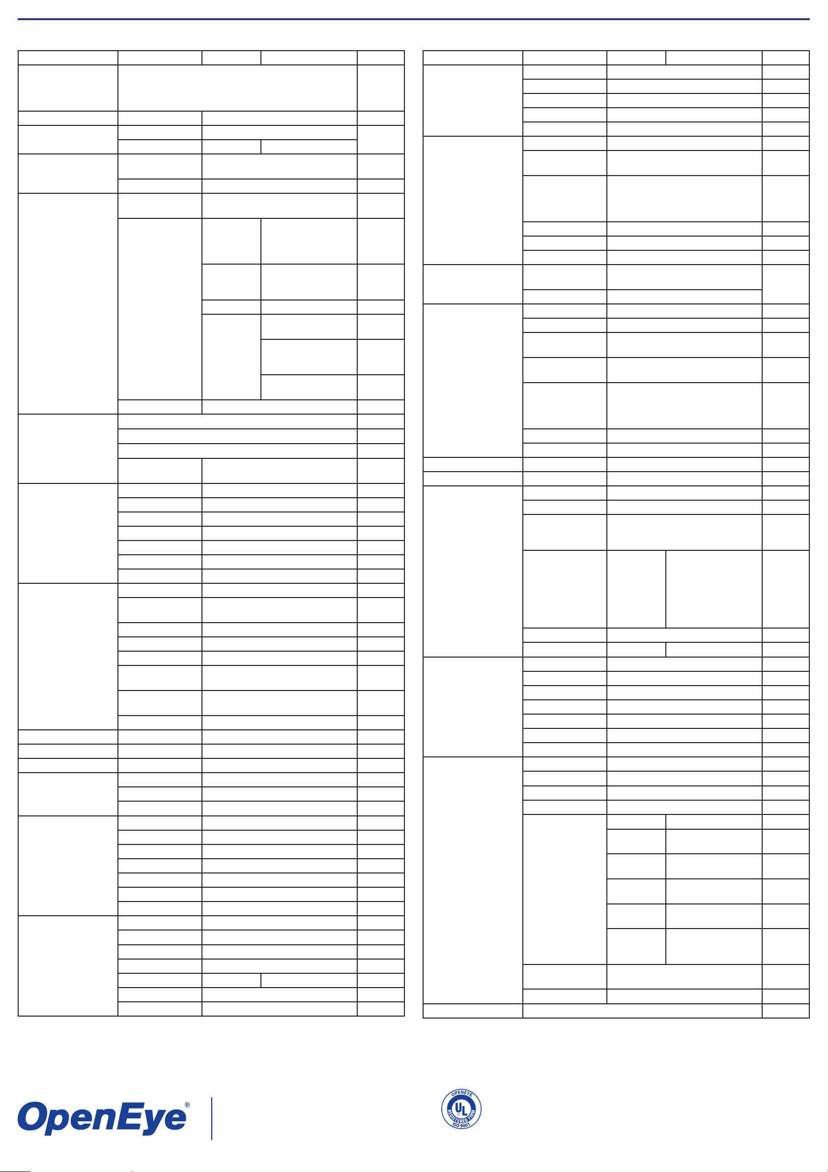
Dome OSD Menu Tree
The OSD setup menu structure of the CM-511 camera is listed below. The star symbol indicates the factory default.
Item Layer 1 Layer 2 Layer 3 Default
<ENGLISH>, <JAPANESE>, <PORTUGUESE>,
LANGUAGE
<SPANISH>, <FRENCH>, <GERMAN>, <ITALIAN>,
<POLISH>, <RUSSIAN>, <TRADITIONAL
ENGLISH
CHINESE>,<SIMPLIFIED CHINESE>, <TURKISH>
DEFAULT CAMERA <ON>, <OFF> ON
BACKLIGHT
FOCUS
<ON> BLC LEVEL <00> ~ <30>
<OFF>
AUTO
AF MODE <NORMAL>, <Z. TRIG.>,
<PT TRIG.>
OFF
NORMAL
MANUAL
EXPOSURE
COMP.
<OFF>, EXPOSURE VALUE: <-
10.5dB> ~ <10.5dB>
OFF
BRIGHT VALUE;
AUTO
SHUTTER SPEED;
IRIS VALUE; GAIN
V ALUE: AUTO
SHUTTER SPEED:
SHUTTER
<1/60> ~ <1/10000>
SEC.
AE MODE
AE MODE
IRIS IRIS VALUE <F1.6>
BRIGHT VALUE:
AUTO
SHUTTER SPEED:
MANUAL
<1/60> ~ <1/10000>
SEC.
GAIN VALUE <-3> dB
~ <28>dB
EXIT + SAVE YES
AUTO (Auto White Balance)
INDOOR
WBC MODE
OUTDOOR
MANUAL
R GAIN <000> ~ <127>
B GAIN <000> ~ <127>
ZOOM SPEED <1> ~ <8> 8
DIGITAL ZOOM <OFF>, <2x> ~ <12x> OFF
SLOW SHUTTER <ON>, <OFF> OFF
IMAGE CTRL
IMAGE INVERSE <ON>, <OFF> OFF
FREEZE <ON>, <OFF> OFF
APERTURE <01> ~ <16> 07
EXIT YES
FLIP <OFF>, <M.E.>, <IMAGE> OFF
ANGLE
ADJUSTER
MIN ANGLE <-10 ~ +10 DEG>
MAX ANGLE <080 ~ 100 DEG>
0
90
SPEED BY ZOOM <ON>, <OFF> OFF
AUTO CALIBRATE <ON>, <OFF> OFF
TELEMETRY CTRL
PASSWORD <ON>, <OFF>
OSD AUTO
<OFF>, <5> ~ <30> SEC.
CLOSE
SYSTEM RESET
SYSTEM RESET <YES>
DEFAULT SYSTEM <YES>
EXIT YES
ID DISPLAY <ON>, <OFF> ON
TITLE DISPLAY <ON>, <OFF> OFF
TITLE SETTING <01> ~ <16> 1
PRESET SET <001>~<256> ENTER
PRESET
PRESET RUN <001>~<256> ENTER
EXIT YES
TOUR LINE <1> ~ <8> 1
TOUR POINT <01> ~ <64> 1
PRESET POS. <001> ~ <255>, <END> END
TOUR
SPEED <01> ~ <15> 1
DWELL TIME <000> ~ <127> SEC. 0
RUN TOUR ENTER
EXIT YES
AUTOSCAN LINE <1> ~ <4> 1
START POINT <TO FIND>, <TO SAVE>
END POINT <TO FIND>, <TO SAVE>
AUTOSCAN
DIRECTION <RIGHT>, <LEFT> RIGHT
SPEED <01> ~ <04> 1
RUN AUTOSCAN ENTER
EXIT YES
Item Layer 1 Layer 2 Layer 3 Default
PATTERN LINE <1> ~ <8>
RECORD START ENTER
PATTERN
RECORD END ENTER
RUN PATTERN ENTER
EXIT YES
HOME FUNCTION <ON>, <OFF> OFF
<PRESET>, <TOUR>, <AUTOSCAN>, <PATTERN>
<001> ~ <256>
<1> ~ <8>
<1> ~ <4>
<1> ~ <8>
PRESET
1
1
1
1
HOME SETTING
SELECT MODE
PRESET POINT
TOUR LINE
AUTOSCAN LINE
PATTERN LINE
RETURN TIME <1> ~ <128> MIN. 1
GO ENTER
EXIT YES
THREADHOLD <MID>, <HI>,
<LOW>
AUTO
IR FUNCTION
<AUTO>
<MANUAL> IR MANUAL <ON>, <OFF>
ALARM PIN <1> ~ <8> 1
ALARM SWITCH <ON>, <OFF> OFF
ALARM TYPE
ALARM ACTION
ALARM SETTING
PRESET POINT
TOUR LINE
AUTOSCAN LINE
PATTERN LINE
<NO> (Normal Open), <NC> (Normal
Close)
<PRESET>, <TOUR>, <AUTOSCAN>, <PATTERN>
<001> ~ <256>
<1> ~ <8>
<1> ~ <4>
<1> ~ <8>
NC
PRESET
1
1
1
1
DWELL TIME <001> ~ <127> Sec., <ALWAYS> ALWAYS
EXIT YES
ALARM DETECT <NONE> NONE
WDR FUNCTION <ON>, <OFF> ON
PRIVACY SWITCH <ON>, <OFF> OFF
TRANSPARENCY <ON>, <OFF> OFF
<BLACK>, <WHITE>,<RED>,
MASK SHADE
<GREEN>, <BLUE>, <CYAN>,
BLACK
<YELLOW>, <MAGENTA>
H CENTER: L/R
PRIVACY MASK
SET MASK <01> ~ <16>
V CENTER: D/U
H SIZE <000> ~
<080>
V SIZE <000> ~
<080>
EXIT + SAVE
CLEAR MASK <01> ~ <16>
EXIT YES
TIME DISPLAY <ON>, <OFF>
SET YEAR <00> ~ <99>
SET MONTH <01> ~ <12>
TIME SETTING
SET DAY <00> ~ <31>
SET HOUR <00> ~ <23>
SET MINUTE <00> ~ <59>
EXIT+SAVE
SWITCH <ON>, <OFF> OFF
POINT <01> ~ <32> 1
HOUR <00> ~ <23> 0
MINUTE <00> ~ <59> 0
NO FUNCTION
PRESET POINT
<001> ~ <256>
TOUR LINE
<1> ~ <8>
AUTOSCAN LINE
<1> ~ <4>
PATTERN LINE <1>
~ <8>
IR FUNCTION
<AUTO>, <ON>,
<OFF>
SCHEDULE
MODE
SCHEDULE
RESET
NONE
PRESET
TOUR
AUTOSCAN
PATTERN
IR
FUNCTION
YES
EXIT YES
EXIT OSD YES
23221 E Knox Ave
Liberty Lake, WA 99019
1.888.542.1103
A12931
Copyright ©2010 OpenEye. All Rights Reserved. Information contained in this document is subject to
change without prior notice. OpenEye does its best to provide accurate information but cannot be held
responsible for typos or mistakes.
29244AB
 Loading...