

Page 1
410-Series Camera
Mini Speed Dome
User Manual
model no.
model no.
CM-410
XM5000
28561AA i
Please carefully read these instructions before using this product.
Save this manual for future use.
Page 2

410 Series Mini Speed Dome Camera
User Manual
Manual Edition 28561AA – DECEMBER 2007
©2000-2007, OPENEYE INC
All Rights Reserved.
No part of this documentation may be reproduced in any means, electronic or mechanical, for any purpose, except as expressed in
the Software License Agreement. Openeye shall not be liable for technical or editorial errors or omissions contained herein. The
information in this document is subject to change without notice.
THE INFORMATION IN THIS PUBLICATION IS PROVIDED “AS IS” WITHOUT WARRANTY OF ANY KIND. THE ENTIRE RISK ARISING
OUT OF THE USE OF THIS INFORMATION REMAINS WITH RECIPIENT. IN NO EVENT SHALL OPENEYE BE LIABLE FOR ANY DIRECT,
CONSEQUENTIAL, INCIDENTAL, SPECIAL, PUNITIVE, OR OTHER DAMAGES WHATSOEVER (INCLUDING WITHOUT LIMITATION,
DAMAGES FOR LOSS OF BUSINESS PROFITS, BUSINESS INTERRUPTION OR LOSS OF BUSINESS INFORMATION), EVEN IF
OPENEYE HAS BEEN ADVISED OF THE POSSIBILITY OF SUCH DAMAGES AND WHETHER IN AN ACTION OR CONTRACT OR TORT,
INCLUDING NEGLIGENCE.
This documentation is copyrighted. All other rights are reserved to OPENEYE INCORPORATED. OPENEYE, Openeye, HDDR, and
High Definition Digital Recorder are registered trademarks of OPENEYE INCORPORATED in the United States and elsewhere;
Windows, and Windows XP Embedded are registered trademarks of Microsoft Corporation. All other brand and product names are
trademarks or registered trademarks of the respective owners.
OPENEYE INCORPORATED
Liberty Lake, WA ● U.S.A.
ii 28561AA
Page 3

Important Safeguards
1. Read Instructions
Read all of the safety and operating instructions before using the product.
2.
Retain Instructions
Save these instructions for future reference.
Attachments / Accessories
3.
Do not use attachments or accessories unless recommended by the appliance manufacturer as they may cause hazards, damage
product and void warranty.
Water and Moisture
4.
Do not use this product near water or moisture.
Installation
5.
Do not place or mount this product in or on an unstable or improperly supported location. Improperly installed product may fall, causing
serious injury to a child or adult, and damage to the product. Use only with a mounting device recommended by the manufacturer, or
sold with the product. To insure proper mounting, follow the manufacturer's instructions and use only mounting accessories
recommended by manufacturer.
Power source
6.
This product should be operated only from the type of power source indicated on the marking label.
Precautions
Operating
z Before using, make sure power supply and others are properly connected.
z While operating, if any abnormal condition or malfunction is observed, stop using the camera immediately and then
contact your local dealer.
Handling
z Do not disassemble or tamper with parts inside the camera.
z Do not drop or subject the camera to shock and vibration as this can damage camera.
z Care must be taken when you clean the clear dome cover. Scratches and dust will ruin the image quality of your camera.
Installation and Storage
z Do not install the camera in areas of extreme temperatures in excess of the allowable range.
z Avoid installing in humid or dusty places.
z Avoid installing in places where radiation is present.
z Avoid installing in places where there are strong magnetic fields and electric signals.
z Avoid installing in places where the camera would be subject to strong vibrations.
28561AA iii
Page 4
WARNING
DANGEROUS HIGH VOLTAGES ARE PRESENT INSIDE THE ENCLOSURE.
DO NOT OPEN THE CABINET.
REFER SERVICING TO QUALIFIED PERSONNEL ONLY.
CAUTION
CAUTION
RISK OF ELECTRIC SHOCK
DO NOT OPEN
CAUTION: TO REDUCE THE RISK OF ELECTRIC SHOCK,
DO NOT REMOVE COVER (OR BACK).
NO USER-SERVICEABLE PARTS INSIDE.
REFER SERVICING TO QUALIFIED SERVICE PERSONNEL.
EXPLANATION OF GRAPHICAL SYMBOLS
The lightning flash with arrowhead symbol, within an equilateral triangle, is intended to alert the user to the
presence of un-insulated "dangerous voltage" within the product's enclosure that may be of sufficient
magnitude to constitute a risk of electric shock to persons.
The exclamation point within an equilateral triangle is intended to alert the user to the presence of
important operating and maintenance (servicing) instruction in the literature accompanying the product.
iv 28561AA
Page 5

Standard Warranty
Openeye warrants all products to be free from defects in workmanship and material under normal use for a period of one year after the date
of purchase. Any defective product that falls under this warranty will, at OpenEye's discretion, be repaired or replaced at no additional
charge. Openeye may elect to replace defective products with new or factory reconditioned products of equal or greater value. Repairs
made necessary by reason of misuse, alteration, normal wear, or accident are not covered under this warranty.
Exceptions to this are listed below:
• Two years on all X-Series, XR Series, H Series, HR Series and E-Series Digital Recorders
• Two years on all Dome Cameras
OpenEye will warrant all otherwise out of warranty replacement parts and repairs for 90 days from the date of OpenEye shipment.
The above warranty is the sole warranty made by OpenEye and is in lieu of all other warranties by OpenEye express and implied, including
without limitation the warranties of merchantability and fitness for a particular purpose. Under no circumstances will OpenEye be liable for
any consequential, incidental, special or exemplary damages arising out of or connected with the sale, delivery, use or performance of the
product, even if OpenEye is apprised of the likelihood of such damages occurring. In no event shall OpenEye liability exceed the purchase
price of the product.
This warranty gives you specific legal rights and you may also have other rights which vary from state to state or country to country.
28561AA v
Page 6

NOTES:
vi 28561AA
Page 7

Table of Contents
INTRODUCTION ............................................................................................................ 1
FEATURES .............................................................................................................................................. 1
Camera Specifications ......................................................................................................................... 1
Advanced Pan/Tilt Functions ............................................................................................................... 1
Preset, Pattern, Swing, Group, and Privacy Mask ............................................................................... 1
PTZ (Pan/Tilt/Zoom) Control ................................................................................................................ 1
OSD (On-Screen Display) .................................................................................................................... 1
Alarm I/O Functions .............................................................................................................................. 2
Reserved Presets for Special Purpose ................................................................................................ 2
PRODUCT & ACCESSORIES ................................................................................................................. 3
Optional Accessories ............................................................................................................................ 3
PART NAMES AND FUNCTIONS ........................................................................................................... 4
DIP SWITCH SETUP ............................................................................................................................... 5
Camera ID Setup .................................................................................................................................. 5
Communication Protocol Setup ............................................................................................................ 5
Reserved for Supplier ........................................................................................................................... 6
INSTALLATION .............................................................................................................. 7
DIRECT INSTALLATION ON THE CEILING ........................................................................................... 7
INSTALLATION USING THE CEILING MOUNT BRACKET ................................................................... 8
INSTALLATION USING THE WALL BRACKET ...................................................................................... 9
INSTALLATION WITH FLUSH MOUNT KIT .......................................................................................... 10
CABLING ................................................................................................................................................ 11
Power Connection .............................................................................................................................. 11
Grounding ...................................................................................................................................... 11
Power Wire Length Specifications ................................................................................................. 11
RS-485 Communication ..................................................................................................................... 12
Video Connection ............................................................................................................................... 12
Alarm Input Connection ...................................................................................................................... 12
Sensor Input ................................................................................................................................... 12
OPERATION ................................................................................................................. 15
CHECK POINTS BEFORE OPERATION .............................................................................................. 15
PRESET AND PATTERN FUNCTION PRE-CHECK ............................................................................. 15
STARTING OSD MENU ......................................................................................................................... 16
RESERVED PRESET ............................................................................................................................ 16
PRESET ................................................................................................................................................. 17
SWING ................................................................................................................................................... 17
PATTERN ............................................................................................................................................... 18
GROUP .................................................................................................................................................. 19
OTHER FUNCTIONS ............................................................................................................................. 20
OSD OF MAIN SCREEN ........................................................................................................................ 21
HOW TO USE THE OSD MENU .................................................................................. 22
GENERAL RULES OF KEY OPERATION FOR MENU ........................................................................ 22
MAIN MENU ........................................................................................................................................... 22
DISPLAY SETUP ................................................................................................................................... 22
Compass Direction Setup................................................................................................................... 22
PRIVACY ZONE MASK SETUP ............................................................................................................ 23
Privacy Zone Area Setup ................................................................................................................... 23
28561AA vii
Page 8

Privacy Zone Size Adjustment ............................................................................................................ 23
CAMERA SETUP .................................................................................................................................... 24
White Balance ..................................................................................................................................... 24
AE Setup (Auto Exposure) .................................................................................................................. 25
MOTION SETUP ..................................................................................................................................... 26
Parking Action Setup .......................................................................................................................... 26
Alarm Input Setup ............................................................................................................................... 27
PRESET SETUP ..................................................................................................................................... 27
Edit Preset Scene ............................................................................................................................... 28
Edit Preset Label ................................................................................................................................ 28
SWING SETUP ....................................................................................................................................... 29
PATTERN SETUP .................................................................................................................................. 30
Edit Pattern ......................................................................................................................................... 30
GROUP SETUP ...................................................................................................................................... 31
Edit Group ........................................................................................................................................... 31
SYSTEM INITIALIZE .............................................................................................................................. 33
Initial Configuration Table ................................................................................................................... 33
APPENDIX: CAMERA ID .............................................................................................. 35
APPENDIX: SPECIFICATIONS .................................................................................... 37
CAMERA SPECIFICATIONS ................................................................................................................. 37
DIMENSIONS ......................................................................................................................................... 38
viii 28561AA
Page 9

NOTES:
28561AA ix
Page 10

NOTES:
x 28561AA
Page 11

INTRODUCTION
FEATURES
CAMERA SPECIFICATIONS
• CCD Sensor : 1/4" Interline Transfer CCD
• Zoom Magnification : × 10 Optical Zoom, × 10 Digital Zoom (Max × 100 Zoom)
• Day & Night Function
• Various Focus Mode: Auto-Focus / Manual Focus / Semi-Auto Focus.
• Independent & Simultaneous Camera Characteristic Setup in Preset operation
ADVANCED PAN/TILT FUNCTIONS
• Max. 360°/sec high speed Pan/Tilt Motion
• Using Vector Drive Technology, Pan/Tilt motions are accomplished with the shortest path. As a result, time to target view is
reduced dramatically and the video stream transfers are natural to watch.
• For jog operation using a controller, an ultra slow speed of 0.05°/sec can be reached, making it very easy to relocate camera to
the desired target view. Additionally, it is easy to move the camera to a desired position with zoom-proportional PanTtilt
movement.
PRESET, PATTERN, SWING, GROUP, AND PRIVACY MASK
• Presets are assignable and characteristics of each preset can be set up independently, such as White Balance, Auto Exposure,
Label and so on. (Max. 127)
• Swing Action enables camera to move automatically between two preset positions at a designated speed. ( Max. 8 set of Swing
actions can be stored)
• Patterns can be recorded and played back. This enables camera to automatically follow any trajectory preset by joystick as
closely as possible. (Max. 4)
• Group Action enables camera to move automatically with a combination of Preset or Pattern or Swing. A Group is composed of
max. 20 entities of Preset/Pattern/Swings. (Max. 8 set of Group action can be stored)
• Privacy Masks are assignable, so as not to intrude on other’s privacy. (4 Privacy Zones)
PTZ (PAN/TILT/ZOOM) CONTROL
• With RS-485 communication, a maximum of 255 cameras can be controlled at the same time.
• Pelco-D or Pelco-P protocol can be selected as a control protocol in the current firmware version.
OSD (ON-SCREEN DISPLAY)
• OSD menu is provided to display the status of camera and to configure the functions interactively.
• The information such as Camera ID, Pan/Tilt Angle, Alarm Input and Preset can be displayed on screen.
28561AA 1
Page 12

ALARM I/O FUNCTIONS
• 4 alarm sensor Inputs are available.
• To completely eliminate external electric noise and shock, alarm sensor Input is decoupled from photo coupler.
• The signal range of sensor Input is from 5 to 12 volts DC to adapt to various applications.
• If an external sensor is activated, camera can be set to move to the corresponding Preset position.
RESERVED PRESETS FOR SPECIAL PURPOSE
• Most camera characteristics can be set up easily and directly with reserved preset, without entering the OSD menu. For more
information, refer to the Reserved Preset section in this manual.
2 28561AA
Page 13
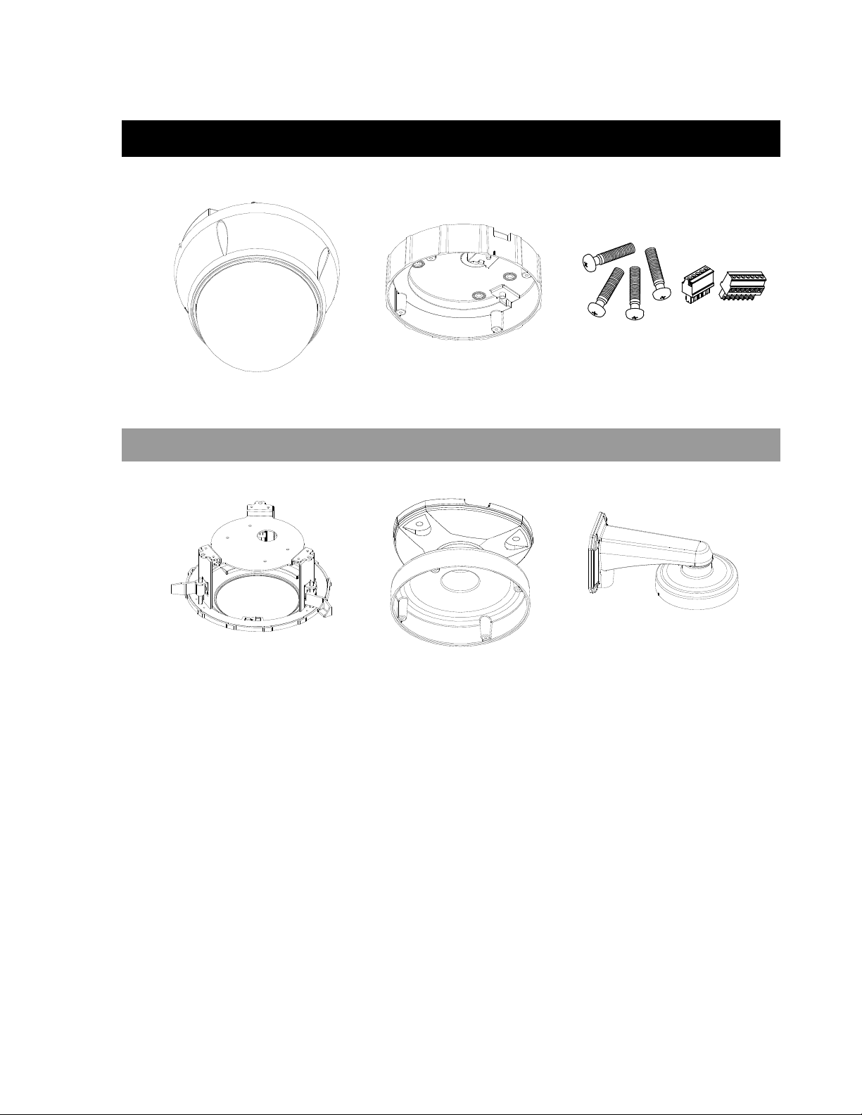
PRODUCT & ACCESSORIES
Main Body Surface Mount Bracket Screws and Terminal Block
OPTIONAL ACCESSORIES
Flush Mount Kit Ceiling Mount Bracket Wall Mount Bracket
28561AA 3
Page 14
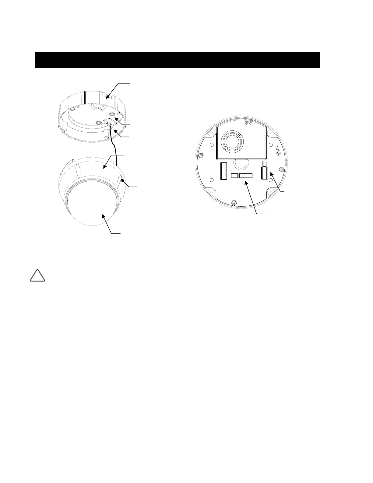
PART NAMES AND FUNCTIONS
Surface Mount Bracket
Mounting Hole
Safety Retention Spring
Main Body
Lock-up Screw
Dome Cover
Main Unit / Surface Mount Bracket Back of Main Unit
Dome Cover
Surface Mount Bracket
Lockup Screw Fixes main unit to surface mount bracket.
Cabling Terminal Block
Safety Retention Spring Pull out from Surface Mount Bracket and connect to Main Body hook.
DIP Switch Adjusts camera ID and protocols.
Do not remove protective vinyl from dome cover before finishing all installation processes to protect
dome cover from scratches or dust.
Used to install the camera directly on the ceiling. Separate the cover first and then attach it directly to
ceiling. Camera must be assembled at the last stage.
Do not use this bracket when installing camera on the wall with wall mount bracket or on the ceiling
with ceiling mount bracket.
During installation, Power, Video, Communication, Alarm Input cables are connected on to this cabling
terminal block.
Cabling
Terminal Block
DIP Switch
4 28561AA
Page 15
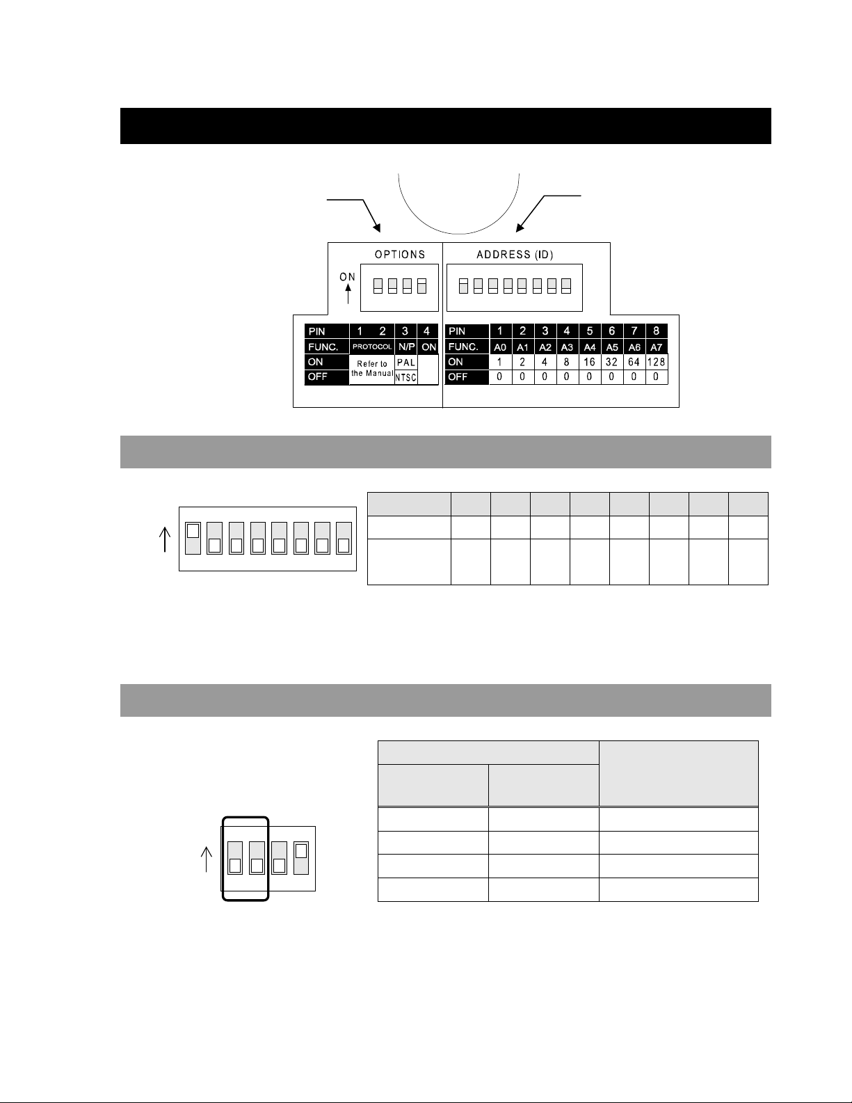
DIP SWITCH SETUP
Before you install the camera, you should set the DIP switches to configure the camera ID and communication protocol.
Communication
Protocol
CAMERA ID SETUP
Camera ID
ON
ON
123456
TIP: See the Appendix for a complete
Camera ID switch setting table.
78
• ID number of camera is set using a binary number. Example is shown below.
Pin 1 2 3 4 5 6 7 8
ID Value 1 2 4 8 16 32 64 128
ex) ID=5 on off on off off off off off
ex) ID=10 off on off on off off off off
• The range of ID is 1~255. Do not use 0 as camera ID. Factory default of
Camera ID is 1.
• If you want to control a certain camera, you must match the camera ID with
Cam ID setting of DVR or Controller.
COMMUNICATION PROTOCOL SETUP
ON
ON
1234
• Select the appropriate Protocol with DIP switch combination.
Switch State
P0
(Pin 1)
OFF OFF PELCO-D, 2400 bps
ON OFF PELCO-D, 9600 bps
OFF ON PELCO-P, 4800 bps
ON ON PELCO-P, 9600 bps
• If you want to control using DVR or P/T controller, their protocol must be
identical to camera. Otherwise, you cannot control the camera.
• If you changed camera protocol by changing DIP S/W, the change will be
effective after you reboot the camera.
• Factory default of protocol is “Pelco-D, 2400 bps”.
P1
(Pin 2)
Protocol
28561AA 5
Page 16

N
RESERVED FOR SUPPLIER
ON
O
1234
• Since Pin 3 ~ Pin 4 are only for supplier, DO NOT CHANGE THEIR ORIGINAL
SETTINGS. If settings are changed, camera will not operate properly.
~ Pin 3
~ Pin 4
PAL / NTSC system selection of Camera. DO NOT CHANGE
THIS PIN.
Factory default is ON. This pin is used for system firmware
upgrade. DO NOT CHANGE THIS PIN.
6 28561AA
Page 17

INSTALLATION
DIRECT INSTALLATION ON THE CEILING
1. To pass cables to upside of ceiling, cut a 2~2.5 inch
(50~60mm) hole in the ceiling panel.
3. Wire cables to terminal block and connect the terminal
blocks to main unit.
2. Fasten surface mount bracket to ceiling with 4 screws.
4. Fasten main unit to surface mount bracket with 4 lock-up
screws.
5. Remove protective vinyl from dome cover.
28561AA 7
Page 18

INSTALLATION USING THE CEILING MOUNT BRACKET
1. Fasten ceiling mount bracket to the ceiling with 3 screws. 2. Wire cables to terminals and connect the terminals to main
unit. Do not use surface mount bracket!
3. Fasten main unit to ceiling mount bracket with 4 screws. 4. Remove protective vinyl from dome cover.
8 28561AA
Page 19

INSTALLATION USING THE WALL BRACKET
1. Fasten the wall bracket to the ceiling with 3 screws. 2. Wire cables to terminals and connect the terminals to main
unit. Do not use surface mount bracket!
3. Fasten main unit to wall mount bracket with 4 screws. 4. Remove protective vinyl from dome cover.
28561AA 9
Page 20

INSTALLATION WITH FLUSH MOUNT KIT
1. Cut holes in the ceiling. (Image not to scale) 2. Align main body bracket with Flush Mount Kit. Fasten with
screws.
65mm (2.56”)
3. Connect fall-proof spring to main body hook. Assemble and
fasten with screws.
7.09”)
(
mm
180
Ø
3 - Ø
80
mm (3
.
15”)
4. Put main body and bracket assembly into main hole.
5. Secure Flush Mount Kit to the ceiling with screws through
6. Cover assembly with bracket cover and turn it clockwise.
the 3 holes on the bracket.
10 28561AA
Page 21

CABLING
Po we r
IrDA
Se n s o r
Controller/DVR
BNC
Monitor
Cabling Terminal Block
Door
Sw i t c h
Sen so r
POWER CONNECTION
• Check the voltage and current capacity of rated power carefully. Rated power is indicated on the back of the main unit.
Rated Power Input Voltage Range Current Consumption
AC 24V AC 17V ~ 29V 0.4 A
Grounding
The GND (ground) wire must be directly connected to the F.G. pin of the cabling terminal block. Failure to connect the ground can
cause damage and failure of the camera and may void the warranty.
If the connection of the GND wire causes video noise, use a video isolator. This is only necessary in some situations.
Power Wire Length Specifications
22 178 feet
20 284 feet
18 451 feet
16 716 feet
14 1138 feet
12 1811 feet
10 2886 feet
28561AA 11
Wire Gauge Maximum Distance
Page 22

RS-485 COMMUNICATION
• For PTZ control, connect this line to the keyboard and DVR. To control multiple cameras at the same time, RS-485
communication lines to cameras are connected in parallel as shown below.
• OpenEye recommends Category 5 or 6 Twisted Pair Cable for the RS-485 wire
Key b oa r d Co nt r ol l er / D VR
RS- 4 8 5
VIDEO CONNECTION
• Connect with BNC coaxial cable.
ALARM INPUT CONNECTION
Sensor Input
Before connecting sensors, check the sensor driver voltage and output signal type. Since sensor output signal types are divided into
Open Collector and Voltage Output types in general, the cabling must be installed properly depending on the signal type.
Signal Description
IN COM+ Connect (+) cable of electric power source for Sensors to this port as shown in the circuit above.
IN1−, IN2−, IN3−, IN4−
If you want to use Alarm Input, the type of sensor must be selected in OSD menu. The sensor types are Normal Open and Normal
Close. If the sensor type is not selected properly, alarm activation will occur opposite of what is desired.
~ Normal Open Output Voltage is high state when sensor is activated
~ Normal Close Output Voltage is high state when sensor is not activated
Connect output of sensors for each port as shown in the circuit above.
12 28561AA
Page 23

NOTES:
28561AA 13
Page 24

NOTES:
14 28561AA
Page 25

OPERATION
CHECK POINTS BEFORE OPERATION
• Before power is applied, please check the cables carefully.
• The camera ID of the controller must be identical to that of the target camera. The camera ID can be checked by reading the
DIP switches on the camera.
• If your controller supports multiple protocols, the protocol must be changed to match to that of the camera.
• If you changed the camera protocol by changing the DIP switch, the change will be effective after you reboot the camera.
• Since the operation method can be different for each controller available, refer to the manual for your controller if camera cannot
be controlled properly. The operation of this manual is based on the standard Pelco® Controller.
PRESET AND PATTERN FUNCTION PRE-CHECK
• Check controller or DVR preset and pattern function operation in advance to take advantage of full camera functions when using
controller or DVR.
• Refer to the following table when using a standard Pelco® protocol controller.
< Go Preset > Input [Preset Number] and press [Preset] button.
< Set Preset > Input [Preset Number] and press [Preset] button for more than 2 seconds.
< Run Pattern > Input [Pattern Number] and press [Pattern] button.
< Set Pattern > Input [Pattern Number] and press [Pattern] button for more than 2 seconds.
• If the controller or DVR has no pattern button or function, use shortcut keys with preset numbers. For more information, refer to
“Reserved Preset” in this manual.
28561AA 15
Page 26

STARTING OSD MENU
Function Using the OSD menu, Preset, Pattern, Swing, Group and Alarm Input function can be configured for
each application
Enter Menu <Go Preset> [95]
RESERVED PRESET
Some Preset numbers are reserved to special functions.
Function Go Preset [95] : Enters OSD menu
Go Preset [131~134] : Runs Pattern Function 1 ~ 4
Go Preset [141~148] : Runs Swing Function 1 ~ 8
Go Preset [151~158] : Runs Group Function 1 ~ 8
Go Preset [170] : Sets Camera BLC Mode to OFF
Go Preset [171] : Sets Camera BLC Mode to ON
Go Preset [174] : Sets Camera Focus Mode to AUTO
Go Preset [175] : Sets Camera Focus Mode to Manual
Go Preset [176] : Sets Camera Focus Mode to SEMI-AUTO
Go Preset [177] : Sets Day & Night Mode to AUTO
Go Preset [178] : Sets Day & Night Mode to NIGHT
Go Preset [179] : Sets Day & Night Mode to DAY
Go Preset [190] : Sets OSD Display Mode to AUTO (Except Privacy Mask)
Go Preset [191] : Sets OSD Display Mode to OFF (Except Privacy Mask)
Go Preset [192] : Setting OSD Display Mode to ON (Except Privacy Mask)
Go Preset [193] : Sets all Privacy Mask Display to OFF
Go Preset [194] : Sets all Privacy Mask Display to ON
16 28561AA
Page 27

PRESET
Function Max. 127 positions can be stored as Preset position. The Preset number can be assigned from 1 to
128, but 95 is reserved for starting OSD menu.
Camera characteristics (i.e. White Balance, Auto Exposure) can be set up independently for each
preset. The label should be left blank and "Camera Adjust" should be set to "GLOBAL" as default. All
characteristics can be set up in the OSD menu.
Set Preset <Set Preset> [1~128]
Run Preset <Go Preset> [1~128]
Delete Preset To delete Preset, use OSD menu.
SWING
Function By using the Swing function, you can make the camera move between two Preset positions repeatedly.
When the swing function runs, the camera moves from the preset assigned as the 1st point to the
preset assigned as the 2nd point in a CW (Clockwise) direction. Then the camera moves from the
preset assigned as the 2nd point to the preset assigned as the 1st point in a CCW (Counterclockwise)
direction.
If the preset assigned as the 1st point is the same as the preset assigned as the 2nd point, the camera
will turn 360° in a CW (Clockwise) direction, then 360° in a CCW (Counterclockwise) direction.
Speed can be set up from 1°/sec to 180°/sec.
Set Swing To set Swing, use OSD menu.
Run Swing Method 1) <Run Pattern> [Swing NO.+10]
Method 2) <Go Preset> [Swing NO.+140]
Delete Swing To delete Swing, use OSD menu.
ex) Run Swing 3 : <Run Pattern> [13]
ex) Run Swing 3 : <Go Preset> [143]
28561AA 17
Page 28

PATTERN
Function Pattern Function allows the camera to memorize a path (often a curved path) created by a controller
joystick for an assigned time. The camera will then retrace the path exactly as memorized.
4 Patterns are available and a Maximum of 1200 communication commands can be stored in a pattern.
Set Pattern
Patterns can be created by one of following two methods.
Method 1) <Set Pattern> [Pattern NO.]
{ Pattern editing screen is displayed as bellow.
{ Movement by Joystick and preset movement can be memorized in a pattern.
{ The remaining memory size is displayed in progress bar.
{ To save the recording, press NEAR key and to cancel, press FAR key.
Method 2) OSD Using OSD Menu: See the section “How to use OSD Menu”.
Run Pattern
Method 1) <Run Pattern> [Pattern NO.]
Method 2) <Go Preset> [Pattern NO.+130]
Delete Pattern Use OSD menu to delete a Pattern.
EDIT PATTERN 1
[NEAR:SAVE /FAR:DELETE]
0/0/x1/N
ex) Run Pattern 2 : <Run Pattern> [2]
ex) Run Pattern 2: <Go Preset> [132]
18 28561AA
Page 29

GROUP
Function
Set Group Use OSD Menu to create a Group.
Run Pattern
Delete Pattern Use OSD menu to delete a Group.
The group function allows a running sequence of Presets, Pattern and/or Swings. Max 8 groups can be
stored. Each group can have max 20 action entities which can be preset, pattern or swing. Preset
speed can be set up and the repeat number of Pattern & Swing can be set up in Group setup. Dwell
time between actions can also be set up.
Method 1) <Run Pattern> [Group NO.+20]
Method 2) <Go Preset> [Group NO.++150]
ex) Run Group 7 : <Run Pattern> [27]
ex) Run Group 7 : <Go Preset> [157]
28561AA 19
Page 30

OTHER FUNCTIONS
Power Up Action This function enables the camera to resume the last action executed before power down. Most actions
such as Preset, Pattern, Swing and Group are available for this function, but Jog actions cannot be
resumed.
Auto Flip If the tilt angle arrives at the top of tilt orbit (90°), zoom module camera will keep moving in the
opposite tilt direction (180°) to keep tracing targets. As soon as zoom module camera passes through
the top of tilt direction (90°), images will be reversed automatically and the F symbol appears on
screen. If this function is set to OFF, tilt movement range is 0 ~ 95°.
Parking Action This function sets the camera to a specific position automatically if operator doesn’t operate the
controller for a while. The Park Time can be defined as an interval from 1 minute to 4 hours.
Alarm Input 4 Alarm Inputs are used. If an external sensor is activated, the camera can be set to move to
corresponding preset position. Note: the latest alarm input is in effect if multiple sensors are activated.
Privacy Zone Mask To protect privacy, max. 4 Privacy Masks can be created in arbitrary locations to hide objects such as
windows, shops or private houses. With the Spherical Coordinates system, a powerful Privacy Zone
Mask function is available.
GLOBAL/LOCAL
Image Setup
SemiAuto Focus
WB (White Balance) and AE (Auto Exposure) can be set up independently for each preset. There are
2 modes, "Global" mode & "Local" mode. The Global mode means that WB or AE can be set up
simultaneously for all presets in the "ZOOM CAMERA SETUP" menu. The Local mode means that
WB or AE can be set up independently or separately for each preset in each preset setup menu. Each
Local WB/AE value will activate correspondingly as the camera arrives at each preset location.
During jog operation, Global WB/AE values should be applied. All Local WB/AE values will not change
although Global WB/AE value changes.
Automatically selects focus mode from Manual Focus or Auto Focus depending on type of operation.
Manual Focus mode activates in preset operation and Auto Focus mode activates during jog
operation. In Manual mode, Focus data for each preset is memorized in advance, and the camera
calls focus data for corresponding presets as soon as it arrives at a preset. This method shortens
focus times.
Focus mode changes to Auto Focus mode automatically when jog operation starts.
20 28561AA
Page 31

OSD OF MAIN SCREEN
Preset Label
Action Title
Image Flip
Alarm Information
Camera ID
PTZ Information
P/T/Z Information Current Pan/Tilt angle in degree, zoom magnification and a compass direction.
Camera ID Current Camera ID(Address).
Action Title Followings are possible Action Titles and their meaning.
"UNDEFINED" When undefined function is called to run
Preset Label The Label stored for specific Preset.
Alarm Input This information shows current state of Alarm Input. If an Input point is ON it will show a
"SET PRESET ×××" When Preset ××× is stored
"PRESET ×××" When camera reach to Preset ×××
"PATTERN ×" When Pattern × is in action
"SWG×/PRESET ×××" When Swing × is in action
number corresponding to each point. If an Input point is OFF, '-' will be displayed.
Example - if points 2 & 3 of inputs are ON, the OSD will show as below:
I:-23-
Image Flip Indicates that images are currently reversed by Auto Flip Function.
28561AA 21
Page 32

HOW TO USE THE OSD MENU
GENERAL RULES OF KEY OPERATION FOR MENU
• The menu items surrounded with ( ) always have a sub menu.
• At all menu levels, to go into sub menu, press the FOCUS NEAR key.
• To go to up one menu level, press the FOCUS FAR key.
• To move from items to item in the menu, use joystick in the Up/Down or Left/Right.
• To change a value of an item, use Up/Down of the joystick in the controller.
• Press the FOCUS NEAR key to save values and Press the FOCUS FAR key to cancel values.
MAIN MENU
System Information Displays system information and configuration.
Display Setup Enable/Disable of OSD display on Main Screen.
Dome Camera Setup Configure various functions of this camera.
SPEED DOME CAMERA
----------------------- <SYSTEM INFORMATION>
<DISPLAY SETUP>
<DOME CAMERA SETUP>
<SYSTEM INITIALIZE>
System Initialize Initializes system configuration and sets all data to factory
default configuration.
EXIT
DISPLAY SETUP
Camera ID [ON/OFF]
PTZ Information [ON/OFF/AUTO]
Action Title [ON/OFF/AUTO]
Preset Label [ON/OFF/AUTO]
Alarm Input [ON/OFF/AUTO]
DISPLAY SETUP
----------------------- CAMERA ID ON
PTZ INFORMATION AUTO
ACTION TITLE AUTO
PRESET LABEL AUTO
ALARM INPUT AUTO
<SET NORTH DIRECTION>
<PRIVACY ZONE>
BACK
EXIT
This menu defines Enable/Disable of OSD display on Main Screen. If an item is set to be
AUTO, the item is displayed only when the value of it is changed.
COMPASS DIRECTION SETUP
SET NORTH DIRECTION
------------------------
MOVE TO TARGET POSITION
[NEAR:SAVE /FAR:CANCEL
22 28561AA
Set North to assign compass direction as criteria. Move camera and press NEAR button
to save.
Page 33

PRIVACY ZONE MASK SETUP
PRIVACY ZONE
------------------------
Mask No [1~4]
MASK NO 1
UNDEFINED
DISPLAY OFF
CLEAR MASK CANCEL
<EDIT MASK>
Select area in image to mask.
Select Mask number. If the selected mask has already
data, camera moves as it was set. Otherwise,
“UNDEFINED” will be displayed under “Mask NO”.
Display [ON/OFF]
Sets if camera makes mask shows or not on images.
BACK
Clear Mask [CANCEL/OK]
EXIT
Deletes data in the selected mask NO.
PRIVACY ZONE AREA SETUP
EDIT MASK 1
------------------------
MOVE TO TARGET POSITION
[NEAR:SELECT/FAR:CANCEL]
Move camera to the area to mask. Then the menu to adjust mask size will be displayed.
PRIVACY ZONE SIZE ADJUSTMENT
EDIT MASK 1
------------------------
(Left/Right) (Left/Right)
(Up/Down) (Up/Down)
[ :ADJUST MASK WIDTH]
[ :ADJUST MASK HEIGHT]
[NEAR:SAVE /FAR:CANCEL]
Adjust mask size. Use joystick or arrow buttons to adjust mask size.
28561AA 23
Page 34

CAMERA SETUP
Focus Mode [AUTO/MANUAL/SEMIAUTO]
ZOOM CAMERA SETUP
----------------------- FOCUS MODE SEMIAUTO
DIGITAL ZOOM ON
LINE LOCK OFF
<WHITE BALANCE SETUP>
<AUTO EXPOSURE SETUP>
Setup the general functions of zoom camera module.
Sets camera focus mode.
SEMIAUTO Mode
Automatically selects focus mode from Manual Focus or
Auto Focus depending on type of operation. Manual Focus
mode activates in preset operation and Auto Focus mode
BACK
EXIT
activates during jog operation. In Manual mode, Focus
data for each preset is memorized in advance, and the
camera calls focus data for corresponding presets as soon
as it arrives at a preset.
Digital Zoom [ON/OFF]
Sets digital zoom function to ON/OFF. When set to OFF,
optical zoom function runs but zoom function stops at the
end of optical zoom magnification.
Line Lock [ON/OFF]
If Line lock sync is ON, video signal is synchronized with
AC power. Video can be fluctuated after setting is
changed.
WHITE BALANCE
Red Adjust [10~60]
WB SETUP - GLOBAL
----------------------- WB MODE AUTO
RED ADJUST -- BLUE ADJUST ---
Blue Adjust [10~60]
WB Mode [AUTO/MANUAL]
In Manual mode, Red and Blue level can be set up
manually
BACK
EXIT
24 28561AA
Page 35

AE SETUP (AUTO EXPOSURE)
AE SETUP - GLOBAL
----------------------- BACKLIGHT OFF
Day/Night [AUTO1/AUTO2/DAY/NIGHT]
DAY/NIGHT AUTO1
BRIGHTNESS 25
IRIS AUTO
SHUTTER ESC
Brightness [0~100]
AGC NORMAL
SSNR MIDDLE
SENS-UP <AUTO>
BACK
EXIT
Backlight [ON/OFF]
Sets Backlight Compensation
AUTO1 exchanges Day/Night mode faster than AUTO2.
Adjusts brightness of images. Iris, Shutter Speed and Gain
are adjusted automatically in correspondence with this
value.
IRIS [AUTO/MANUAL(0~100)]
If Iris is set to Auto, Iris should have highest priority in
adjusting AE and Shutter Speed should be fixed.
If Iris is set to Manual, Iris should be fixed and Iris has
lower priority in adjusting AE, in comparison with others.
Shutter Speed
[ESC/A.Flicker/Manual(×128~1/120000 sec)]
If Iris is set to Manual and Shutter Speed is set to ESC
(Electronic Shutter Control), Shutter Speed should have
highest priority. If Shutter Speed is set to A.Flicker, to
remove Flicker, Shutter Speed should be set to 1/100 sec.
AGC [OFF/NORMAL/HIGH]
Enhances image brightness automatically in case that
luminance level of image signal is too low.
SSNR [OFF/LOW/MIDDLE/HIGH]
Enhances images by filtering noise when the level of
Electronic Gain is too high and creates noise.
SENS-UP [AUTO(2~128)/OFF]
Activates Slow Shutter function when luminance of image
(signal) is too dark.
It is possible to set up the maximum number of frames
stacked on one another by Slow Shutter function.
28561AA 25
Page 36

MOTION SETUP
Motion Lock [ON/OFF]
Power Up Action [ON/OFF]
Auto Flip [ON/OFF]
MOTION SETUP
----------------------- MOTION LOCK OFF
PWR UP ACTION ON
AUTO FLIP ON
JOG MAX SPEED 120/SEC
JOG DIRECTION INVERSE
FRZ IN PRESET OFF
<PARKING ACTION SETUP>
<ALARM INPUT SETUP>
BACK
EXIT
Setup the general functions of Pan/Tilt motions.
If Motion Lock is set to ON, it is impossible to set up and
delete Preset, Swing, Pattern and Group. It is only possible
to run these functions. To set up and delete these
functions, enter into OSD menu.
Refer to “Other Functions" section.
Refer to “Other Functions" section.
Jog Max Speed
[1°/sec ~360°/sec]
Sets maximum jog speed. Jog speed is inversely
proportional to zoom magnification. As zoom magnification
goes up, pan/tilt speed goes down.
Jog Direction [INVERSE/NORMAL]
If you set this to ‘Inverse’, the view on the screen will move
in the same direction as jog tilt. If ‘Normal’ is selected, the
view on the screen will move in the opposite direction.
Freeze in Preset [ON/OFF]
At start point of preset movement, camera will freeze the
image of start point. Camera keeps displaying the image of
start point during preset movement and does not display
the images received during preset movement. As soon as
camera stops at preset end point, camera will display live
images received at the preset end point.
Availability of this function will vary by model.
PARKING ACTION SETUP
Park Enable [ON/OFF]
Wait Time [1 minute ~ 4 hour]
Park Action [HOME/PRESET/PATTERN/SWING/GROUP]
PARKING ACTION SETUP
----------------------- PARK ENABLE OFF
WAIT TIME 00:10:00
PARK ACTION HOME
BACK
EXIT
26 28561AA
If Park Enable is set to ON, camera runs assigned function automatically if there is no
PTZ command during assigned "Wait Time".
The time is displayed with "hh:mm:ss" format and can be
changed in 1 min units.
HOME
Camera moves to home position if there is no PTZ
command during assigned "Wait Time".
Page 37

ALARM INPUT SETUP
ALARM INPUT SETUP
----------------------- ALARM1 TYPE N.OPEN
ALARM2 TYPE N.OPEN
ALARM3 TYPE N.OPEN
ALARM4 TYPE N.OPEN
ALARM1 ACT NOT USED
ALARM2 ACT NOT USED
ALARM3 ACT NOT USED
ALARM4 ACT NOT USED
BACK
EXIT
Matches the Alarm sensor input to one of Preset positions. If an external sensor is
activated, camera will move to corresponding preset position when this item is
predefined.
Alarm × Type
[Normal OPEN/Normal CLOSE]
Sets sensor input type.
Alarm × Action
[NOT USED/PRESET 1~128]
Assign counteraction Preset position to each Alarm input.
PRESET SETUP
PRESET SETUP
----------------------- PRESET NO. 1
CLR PRESET CANCEL
<EDIT SCENE>
<EDIT LABEL> LABEL123
Clear Preset [CANCEL/OK]
CAM ADJUST GLOBAL
Edit Preset Scene Redefine current Preset scene position (i.e. PTZ).
BACK
EXIT
Edit Preset Label Edits Label to show on monitor when preset runs. MAX. 10
CAM Adjust [GLOBAL/LOCAL]
Preset Number [1~128]
If a selected preset is already defined, camera moves to
pre-defined position and preset characteristics such as
Label and Relay Outputs show on monitor. If a selected
preset is not defined, “UNDEFINED” shows on monitor.
Delete current Preset data
alphabets are allowed.
WB(White Balance) and AE(Auto Exposure) can be set up
independently for each preset. There are 2 modes,
"Global" mode & "Local" mode. The Global mode means
that WB or AE can be set up totally and simultaneously for
all presets in "ZOOM CAMERA SETUP" menu.
The Local mode means that WB or AE can be set up
independently or separately for each preset in each preset
setup menu. Each Local WB/AE value should activate
correspondingly when camera arrives at each preset
location. During jog operation, Global WB/AE value should
be applied.
All Local WB/AE values should not change although the
Global WB/AE value changes. If “Local’’ is selected, Menu
to set WB/AE shows on monitor.
28561AA 27
Page 38

EDIT PRESET SCENE
1. Using Joystick, move camera to desired position.
EDIT SCENE - PRESET 1
------------------------
2. By pressing NEAR key, save current PTZ data.
3. Press FAR key to cancel.
MOVE TO TARGET POSITION
[NEAR:SAVE /FAR:CANCEL]
EDIT PRESET LABEL
2. Using Left/Right/Up/Down of joystick, move to an appropriate character from the
EDIT LABEL - PRESET 1
----------------------- [ ]
--------- 1234567890 OK
ABCDEFGHIJ CANCEL
KLMNOPQRST
UVWXYZabcd
efghijklmn
opqrstuvwx
yz<>-/:.
----------
1. Edits label to show on monitor when camera arrives at presets. In Edit Label menu,
a reverse rectangle is the cursor. As soon as alphabetic selection is complete, the
cursor will move to the next digit.
Character set. To choose the character, press the NEAR key.
3. If you want to use blank, choose Space character (" "). If you want to delete a
character before, use back space character (" ←").
4. When you complete the Label editing, move cursor to "OK" and press NEAR key to
save completed label. To abort current change, move cursor to "Cancel" and press
NEAR key.
28 28561AA
Page 39

SWING SETUP
SWING SETUP
----------------------- SWING NO. 1
1ST POS. NOT USED
2ND POS. NOT USED
1st Position
SWING SPEED 30/SEC
CLEAR SWING CANCEL
Swing Number [1~8]
Select Swing number to edit. If a selected Swing is not
defined, "NOT USED" is displayed in 1st Position and 2nd
Position
[PRESET 1~128]
2nd Position
Set up the 2 position for Swing function. If a selected
preset is not defined, "UNDEFINED" will be displayed as
BACK
EXIT
shown below.
SWING SETUP
----------------------- SWING NO. 1
1ST POS. PRESET5
2ND POS. NOT USED
UNDEFINED
When swing function runs, the camera will move from the
preset assigned as the 1st point to the preset assigned as
the 2nd point in a CW (Clockwise) direction. Then the
camera will move from the preset assigned as the 2nd
point to the preset assigned as the 1st point in a CCW
(Counterclockwise) direction. If the preset assigned as the
1st point is same as the preset assigned as the 2nd point,
the camera will turn 360° in CW direction and then turn
360° in CCW direction.
Swing Speed
[1°/sec ~180°/sec]
Sets Swing speed from 1°/sec to 180°/sec.
Clear Swing [CANCEL/OK]
Deletes current Swing data.
28561AA 29
Page 40

PATTERN SETUP
PATTERN SETUP
----------------------- PATTERN NO. 1
UNDEFINED
CLR PATTERN CANCEL
<EDIT PATTERN>
Pattern Number [1~4 ]
Selects Pattern number to edit.
If a selected pattern number is not defined,
"UNDEFINED" will be displayed under selected pattern
number.
Clear Pattern [CANCEL/OK]
Deletes data in current pattern
Edit Pattern Starts editing pattern.
BACK
EXIT
EDIT PATTERN
EDIT PATTERN 1
------------------------
MOVE TO START POSITION
[NEAR:START /FAR:CANCEL]
EDIT PATTERN 1
3. To save data and exit, press NEAR key. To cancel recording and delete record
1. Using Joystick, move to start position with appropriate zoom. To start pattern
recording, press NEAR key. To exit this menu, press FAR key.
2. Move camera with controller joystick or run preset function to memorize a path
(often a curved path) in a selected pattern. The total memory size and remaining
memory size are displayed in the form of a bar. Maximum 1200 communication
commands can be stored in a pattern.
data, press FAR key.
[NEAR:SAVE /FAR:DELETE]
0/0/x1/N
30 28561AA
Page 41

GROUP SETUP
GROUP SETUP
----------------------- GROUP NO. 1
UNDEFINED
CLEAR GROUP CANCEL
<EDIT GROUP>
Clear Group [CANCEL/OK]
Group Number [1~8]
Selects Group number to edit.
If a selected Group number is not defined, "UNDEFINED"
will be displayed under selected Group number.
Deletes data in current Group
Edit Group Starts editing Group.
BACK
EXIT
EDIT GROUP
EDIT GROUP 1
----------------------- NO ACTION ### DWELL OPT
----------------------- 1 NONE
2 NONE
3 NONE
4 NONE
5 NONE
----------------------- SAVE
CANCEL [NEAR:EDIT]
EDIT GROUP 1
----------------------- NO ACTION ### DWELL OPT
----------------------- 1 NONE
2 NONE
3 NONE
4 NONE
5 NONE
----------------------- SAVE [NEAR:EDIT ACT]
CANCEL [FAR :EDIT END]
1. Press Near key in “NO” list to start Group setup.
2. Note that MAX. 20 Functions are allowed in a Group. Move cursor up/down and
press Near key to set up.
EDIT GROUP 1
----------------------- NO ACTION ### DWELL OPT
------------------------
Action ### [NONE/PRESET/SWING/PATTERN]
1 NONE
2 NONE
DWELL [0 second ~ 4 minutes]
3 NONE
4 NONE
5 NONE
------------------------
OPT Option. Displays the preset speed when preset is set in
SAVE [ :MOVE CURSOR]
CANCEL [ :CHANGE VAL.]
3. Set up Action, Dwell time and Option. Note that selected item is displayed in
reverse. Move cursor Left/Right to select items and move cursor Up/Down to
change each value.
Sets Dwell Time between functions
Action. Displays the number of repeats when Pattern or
Swing is selected in Action
28561AA 31
Page 42

EDIT GROUP 1
----------------------- NO ACTION ### DWELL OPT
----------------------- 1 PRESET 1 00:03 360
2 NONE
3 NONE
4 NONE
5 NONE
----------------------- SAVE [ :MOVE CURSOR]
CANCEL [ :CHANGE VAL.]
4. Set up items such as Action, ###, Dwell and OPT.
EDIT GROUP 1
----------------------- NO ACTION ### DWELL OPT
----------------------- 1 PRESET 1 00:03 360
2 NONE
3 NONE
4 NONE
5 NONE
----------------------- SAVE [NEAR:EDIT ACT]
CANCEL [FAR :EDIT END]
5. After finishing setup of an Action, press Near key to one-upper-level menu(Step 2).
Move cursor Up/Down to select Action number and repeat Step 2 ~ Step 4 to edit
selected Group.
EDIT GROUP 1
----------------------- NO ACTION ### DWELL OPT
----------------------- 1 PRESET 1 00:03 360
2 NONE
3 NONE
4 NONE
5 NONE
----------------------- SAVE
CANCEL
6. After finishing setup of all Actions, press FAR key to exit. Then cursor should be
moved to “SAVE”. Press Near key to save data.
32 28561AA
Page 43

SYSTEM INITIALIZE
SYSTEM INITIALIZE
----------------------- CLEAR ALL DATA NO
Clear Display Set Initializes Display Configuration
CLR DISPLAY SET NO
CLR CAMERA SET NO
Clear Camera Set Initializes Camera Configuration
CLR MOTION SET NO
CLR EDIT DATA NO
Clear Motion Set Initializes Motion Configuration
REBOOT CAMERA NO
REBOOT SYSTEM NO
Clear Edit Data Deletes Preset Data, Swing Data, Pattern Data and Group
BACK
EXIT
Reboot Camera Reboots Zoom Camera module
Clear All Data Deletes all configuration data such as display, camera,
motion setup and so on.
Data
Reboot System Reboots Speed Dome Camera
INITIAL CONFIGURATION TABLE
Display Configuration Camera Configuration
Camera ID ON Focus Mode SemiAuto
PTZ Information AUTO Digital Zoom ON
Action Title AUTO Line Lock OFF
Preset Label AUTO White Balance AUTO
Alarm Input AUTO Backlight OFF
North Direction
Pan 0°
Privacy Zone Undefined Brightness 25
Iris AUTO
Shutter ESC
Motion Configuration AGC NORMAL
Motion Lock OFF SSNR MIDDLE
Power Up Action ON SENS-UP AUTO (4 Frame)
Auto Flip ON
Jog Max Speed
120°/sec
Jog Direction INVERSE Preset 1~128 Undefined
Freeze In Preset OFF Swing 1~8 Undefined
Park Action OFF Pattern 1~4 Undefined
Alarm Action OFF Group 1~8 Undefined
Day&Night AUTO1
User Edit Data
28561AA 33
Page 44

NOTES:
34 28561AA
Page 45

APPENDIX: CAMERA ID
Camera
ID bit1 bit2 bit3 bit4 bit5 bit6 bit7 bit8
1 On Off Off Off Off Off Off Off
2 Off On Off Off Off Off Off Off
3 On On Off Off Off Off Off Off
4 Off Off On Off Off Off Off Off
5 On Off On Off Off Off Off Off
6 Off On On Off Off Off Off Off
7 On On On Off Off Off Off Off
8 Off Off Off On Off Off Off Off
9 On Off Off On Off Off Off Off
10 Off On Off On Off Off Off Off
11 On On Off On Off Off Off Off
12 Off Off On On Off Off Off Off
13 On Off On On Off Off Off Off
14 Off On On On Off Off Off Off
15 On On On On Off Off Off Off
16 Off Off Off Off On Off Off Off
17 On Off Off Off On Off Off Off
18 Off On Off Off On Off Off Off
19 On On Off Off On Off Off Off
20 Off Off On Off On Off Off Off
21 On Off On Off On Off Off Off
22 Off On On Off On Off Off Off
23 On On On Off On Off Off Off
24 Off Off Off On On Off Off Off
25 On Off Off On On Off Off Off
26 Off On Off On On Off Off Off
27 On On Off On On Off Off Off
28 Off Off On On On Off Off Off
29 On Off On On On Off Off Off
30 Off On On On On Off Off Off
31 On On On On On Off Off Off
32 Off Off Off Off Off On Off Off
33 On Off Off Off Off On Off Off
34 Off On Off Off Off On Off Off
35 On On Off Off Off On Off Off
36 Off Off On Off Off On Off Off
37 On Off On Off Off On Off Off
38 Off On On Off Off On Off Off
39 On On On Off Off On Off Off
40 Off Off Off On Off On Off Off
41 On Off Off On Off On Off Off
42 Off On Off On Off On Off Off
43 On On Off On Off On Off Off
44 Off Off On On Off On Off Off
45 On Off On On Off On Off Off
46 Off On On On Off On Off Off
47 On On On On Off On Off Off
48 Off Off Off Off On On Off Off
49 On Off Off Off On On Off Off
50 Off On Off Off On On Off Off
51 On On Off Off On On Off Off
Camera
ID bit1 bit2 bit3 bit4 bit5 bit6 bit7 bit8
52 Off Off On Off On On Off Off
53 On Off On Off On On Off Off
54 Off On On Off On On Off Off
55 On On On Off On On Off Off
56 Off Off Off On On On Off Off
57 On Off Off On On On Off Off
58 Off On Off On On On Off Off
59 On On Off On On On Off Off
60 Off Off On On On On Off Off
61 On Off On On On On Off Off
62 Off On On On On On Off Off
63 On On On On On On Off Off
64 Off Off Off Off Off On On Off
65 On Off Off Off Off Off On Off
66 Off On Off Off Off Off On Off
67 On On Off Off Off Off On Off
68 Off Off On Off Off Off On Off
69 On Off On Off Off Off On Off
228 Off Off On Off Off On On On
229 On Off On Off Off On On On
230 Off On On Off Off On On On
231 On On On Off Off On On On
232 Off Off Off On Off On On On
233 On Off Off On Off On On On
234 Off On Off On Off On On On
235 On On Off On Off On On On
236 Off Off On On Off On On On
237 On Off On On Off On On On
238 Off On On On Off On On On
239 On On On On Off On On On
240 Off Off Off Off On On On On
241 On Off Off Off On On On On
242 Off On Off Off On On On On
243 On On Off Off On On On On
244 Off Off On Off On On On On
245 On Off On Off On On On On
246 Off On On Off On On On On
247 On On On Off On On On On
248 Off Off Off On On On On On
249 On Off Off On On On On On
250 Off On Off On On On On On
251 On On Off On On On On On
252 Off Off On On On On On On
253 On Off On On On On On On
254 Off On On On On On On On
255 On On On On On On On On
1 2 4 8 16 32 64 128
28561AA 35
Page 46

NOTES:
36 28561AA
Page 47

APPENDIX: SPECIFICATIONS
CAMERA SPECIFICATIONS
Model CM-410
CCD 1/4'' Interline Transfer CCD
Camera
Pan/Tilt
General
Max. Pixels
Effective Pixels
Horizontal Res. 500 TV (Color), 570 TV (B/W)
S/N Ratio 50 dB (AGC Off)
Zoom
Focal length F1.8, f=3.8~38mm
Min. illumination 0.7 Lux (Color) / 0. 02 Lux (B/W), 50 IRE
Day & Night Auto / Day / Night(ICR)
Focus Auto / Manual / SemiAuto
Iris Auto / Manual
Shutter Speed x128 ~ 1/120000 sec
AGC Normal / High / Off
White Balance Auto / Manual(Red, Blue Gain Adjustable)
BLC Low / Middle / High / Off
Flickerless Selectable
SSNR Low / Middle / High / Off
Range
Pan/Tilt Speed
Preset 127 Preset (Label, Camera Image Setting)
Pattern 4 Pattern, 1200 commands(about 5 minute)/Pattern
Swing 8 Swing
Group 8 Group (20 action entities per Group)
Other Functions Auto Flip, Auto Parking, Power Up Action etc.
Communication RS-485
Protocol Pelco-D, Pelco-P selectable
Privacy Zone 4 Zone
Alarm Input 4 Input
OSD Menu / PTZ information etc
Rated Power**
Dimension
Weight about 1.3 Kg
Operating Temp.
Pan :
Tilt :
Preset :
Manual :
Swing :
811(H)×508(V) 410K
768(H)×494(V) 380K
×10 Optical Zoom, ×10 Digital Zoom
360°(Endless)
180° (Auto-Flip), 95° (Normal)
360°/sec
0.05 ~ 360°/sec (proportional to zoom)
1~ 180°/sec
AC 24V / 0.4A
Dome :
Housing :
∅115
∅154.5 × 158.5(H) mm
0°C ~ 40°C
* Specifications of this product are subject to change without notice.
** Check the voltage and current capacity of rated power carefully.
Appearance
Ceiling Mount
In-Ceiling Mount
Main Unit
Wall Mount
28561AA 37
Page 48

DIMENSIONS
All measurements in millimeters (mm)
Main Unit & Surface Mount Bracket Ceiling Mount Bracket
Wall Mount Bracket
38 28561AA
Page 49

28561AA 39
Page 50

www.openeye.net
1-888-542-1103
© 2007 Openeye Inc.
All rights reserved. No part of this publication may be reproduced by any means without written permission from Openeye Inc. The information
in this publication is believed to be accurate in all respects. However, Openeye cannot assume responsibility for any consequences resulting
from the use thereof. The information contained herein is subject to change without notice. Revisions or new editions to this publication may be
issued to incorporate such changes.
40 28561AA
 Loading...