

OpenEye CM-159 Quick Installation Manual
Hardware Kit Contents
• 1/2” Rubber Grommet
• 3/4” Rubber Grommet
• Screw Pack
• Torx Driver
• Quick Install Adaptor
• Wire-Ended Power Adaptor Lead
Template
Cable access:
Surface Mount (Wall or Ceiling)
Using the Quick Install Adaptor: Using screws:
T1
T2
Side Knock-out
Side Knock-out
Side Knock-out
Side Knock-out
Cable Access
T1
T1
T1
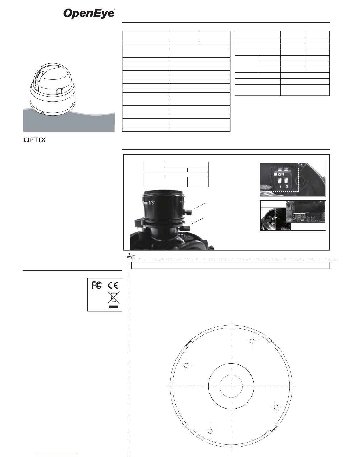
Create a 1.5” (38mm) hole in the mounting surface as
indicated by T2. The hole can also be used for cable access.
Drill four holes at template positions T1 and use the screws
and anchors provided with the camera if they are appropriate
for the mounting surface.
When mounting the camera on a surface with the provided
screws, use one of the side knock-outs, as indicated on the
template, for cable entry.
To thread the cables through the mounting surface, cut a 3/4”
(19mm) hole as indicated by the Cable Access markings
inside T2.
Lens Specifications
Regulatory Compliance
Emissions
Immunity
FCC part 15 Class B
CE: EN55011
ICES-003
EN55022
CISPR 11
CISPR22
ANSI C63.4
CE:
EN50130-4
RoHS
FCC COMPLIANCE:
This equipment has been tested and found to comply with the limits
for a Class B digital device, pursuant to Part 15 of the FCC Rules.
These limits are designed to provide reasonable protection against
harmful interference in as residential installation. This equipment
generates uses and can radiate radio frequency energy and, if not
installed and used in accordance with the instructions, may cause
harmful interference to radio communications. However, there is no
guarantee that interference will not occur in a particular installation.
If this equipment does harmful interference to radio or television
reception, which can be determined by turning the equipment off and
on, the user is encouraged to try \to correct the interference by one or
more of the following measures:
Reorient or relocate the receiving antenna.
Increase the separation between the equipment and receiver.
Connect the equipment into an outlet on a circuit different from that to
which the receiver is connected.
Consult the dealer or an experienced Radio/TV technician for help.
CISPR 22 WARNING:
This is a Class B product. In a domestic environment this product
may cause radio interference in which case the user may be required
to take adequate measures.
POWER SUPPLY REQUIREMENTS:
For use with listed Audio/Video product and only connected to 15W
or less power supply.
*Power supply should be a NEC Class 2 / LPS Supply.
EQUIPMENT MODIFICATION CAUTION:
Equipment changes or modifications not expressly approved by
seller, the party responsible for FCC compliance, could void the
user’s authority to operate the equipment and could create a
hazardous condition.
This class B digital apparatus complies with Canadian ICES-003.
Cet appareil numérique de la classe B est conforme à la norme
NMB-003 du Canada.
General Specifications
Type / Format
Model No.
Lens Focal Length
Scanning Element
Image Picture Element
Effective Picture Element
Resolution (TV lines)
Minimum Illumination
S/N Ratio
Back Light Compensation
Exposure Control
Sync System
Gamma Compensation
Video Output
White Balance
Auto White Balance Range
Power Range
Power Consumption
Operating Temperature
Storage Temperature
CM-159CM-150
9mm~22mm4mm~9mm
NTSC
1/3” Sony SuperHAD CCD (Interline)
Imaging DSP
Sony SS-11X
500
1.2 Lux @ F1.6 (50 IRE)
48dB
Central Area for DC IRIS Lens
INT
0.45
Automatic White Balance
2500K – 9700K
DC 12V ±10%
1.8W (Max)
-10°C ~ +50°C
-20°C ~ +60°C
DC Type Auto IRIS Control
1.0Vpp, 75Ω Unbalanced
768(H) x 494(V)
2:1 Interlace
H15.734KHz / V :59.9Hz
Camera Adjustments
A3
A4
* AI Level Adjustment is factory set;
it should not require adjustment.
A1
A2
Quick Installation Manual
CM-150
CM-159
model no
Tamper Resistant
Indoor Mini Dome
Please carefully read these instructions before using this product.
Save this manual for future use.
28395AC
A
Vari-Focal Lens
Switch 2
ON
OFF
Back Light Compensation
Auto Gain Control
OFF
(Normal Mode)
ON
(T
urbo Mode)
Switch 1
Function Control Dip Switches
Focus AdjusterA1 :
Field of View
Adjustment
A2 :
A3 : Function Control
Dip Switches
A4 :
AI Level
Adjustment*
BLC
A
GC-UP
Focal Length
F-No.
Iris Range
Minimum Object Distance
Field Of View
Diagonal
Horizontal
Vertical
4mm~9mm
F1.6
F1.6~F2.4
50cm
92.8º~39.4º
71.0º~31.6º
51.6º~23.6º
9mm~22mm
F1.8
F1.8~F360
15cm(6”)
39.0º~17.6º
30.7º~14.1º
22.7º~10.6º
ON/OFF
ON/OFF
AUTO
Low Light Chroma
Suppression
Template
Quick Install Adaptor
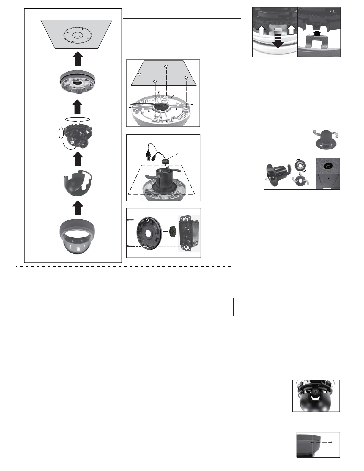
2. Mount the Dome Enclosure
Locking Arms
Install Quick Install Adaptor on indoor ceiling
A. Using the Base Mounting Holes:
B. Using the Quick Install Adaptor (Optional):
C. Mount on a Single Gang Box (US):
PULL
1. Prepare Surface for Installation
Pull the tab and remove the camera module
Tighten tamper-proof screw
Tamper-proof Screw
2
3
4
5
Dome Base
Camera Module
Camera Liner
Dome Cover
T2
1
ROTATE 360°
PAN 360°
TILT 90°
T1
T1
T1
T1
Installation
Use the supplied torx driver
and the tamper-proof screw to
secure the dome cover.
Replace the dome cover and rotate it clockwise.
Carefully fit the camera liner
over the camera until it
snaps in place. Do not
obstruct the camera lens.
Use the included template to mark and prepare the mounting area.
To mount the base, fist remove the camera module by gently
pulling down the tabs that hold the camera module in place (see
image right) and remove the camera module. To re-assemble the
camera, gently pull down the tabs and insert the camera module.
When mounting the dome on a ceiling or wall using screws, first
knock-out the screw holes that correspond to the template marks T1.
This can be done using a Phillips screwdriver.
Push the cables through the dome base and 3/4” rubber grommet.
Make sure the grommet is properly installed to prevent dust penetration. The cables may be routed through the mounting surface if an
appropriate hole is cut using the template markings T2. If using the
side knock-out, make sure the video cables are properly arranged in
the cable notch and exit the side knock-out without being crushed.
When mounting the dome on a ceiling using the quick
install adapter, use the template to cut a hole on the
T2 markings.
Insert the adapter into the hole and use the screws to
adjust the position of the two locking arms on the
adapter, securing it to the mounting surface.
Push the cables through
the 1/2” rubber grommet
and the adapter. Make
sure the grommet is
properly installed on the
quick install adapter to
prevent dust penetration.
When mounting the camera to a single gang box, carefully remove the
screws from the gang box. Insert the 3/4” rubber grommet into the
camera base to prevent dust penetration, then push the cables through
the dome base and rubber grommet.
Mount the camera base on the gang box using the two screws
removed previously. Tighten the screws to secure the base.
Removing the dome cover and camera liner
Gently turn the dome cover counter-clockwise to unlock and remove
from the dome base. Remove the camera liner by gently pulling the
liner free of the four notches in the camera base.
Opening a side knock-out
Open a side knock-out on the dome base to the size
required to allow cable entry.
Use the base mounting holes to install the dome base
to a wall or ceiling with screws.
Note: When using the Quick Install Adapter, reassemble the dome and mount the whole camera
dome onto the adapter.
Push the video power cables through the opening
Feed the pre-connected video power cables through
the appropriate opening. Make sure the cable is
properly positioned and exits out of the side knock-out
(if required).
Adjust the camera position
Adjust the camera position by rotating and panning the
camera module. The focus and range of the lens can
be adjusted on some models. See the Camera
Adjustments section.
Install the dome liner on the camera module
C
Video-Power Cables
B
Single Gang BoxDome Base
T1
T1
Mount on a pre-installed US Single Gang Box
3/4”
Rubber
Grommet
1/2” Rubber Grommet
Mount with the Quick Install Adaptor
Side
Knock-outs
Mounting Surface
Mount with the Dome Base
Cable Notch
Cable Notch
3/4”
Rubber Grommet
A
Mounting Surface
6. Tighten the Tamper proof Screw
4. Install the Camera Liner
5. Replace the Dome Cover
3. Install Camera Module
 Loading...