

Page 1
Camera
OE-C6412-R
www.openeye.net
Indoor IP Dome Camera
User Manual
Accessories
CA-510G
CA-510W
CA-510C
CA-510P25
CA-510P50
CA-510PML
CA-510PMS
CA-510PA25
CA-510PA50
Page 2

2
Page 3

32700AA 3
High Resolution Indoor IP Dome Camera (OE-C6412-R)
User Manual
Manual Edition 32700AA – APRIL 2014
©2014, OPENEYE
All Ri ghts Res erved.
No part of this documentation may be reproduced in any means, electronic or mechanical, for any
purpose, except as expressed in the Software License Agreement. OpenEye shall not be liable for
technical or editorial errors or omissions contained herein. The information in this document is
subject to change without notice.
The information in this publication is provided “as is” without warranty of any kind. The entire risk
arising out of the use of this information remains with recipient. In no event shall OPENEYE be
liable for any direct, consequential, incidental, special, punitive, or other damages whatsoever
(including without limitation, damages for loss of business profits, business interruption or loss of
business information), even if OPENEYE has been advised of the possibility of such damages and
whether in an action or contract or tort, including neg lige nce .
This documentation is copyrighted. All other rights are reserved to OPENEYE. OPENEYE, and
OpenEye, are registered trademarks of OPENEYE in the United States and elsewhere; Windows,
and Windows XP Embedded are registered trademarks of Microsoft Corporation. All other brand
and product names are trademarks or registered trademarks of the respective owners.
OPENEYE
Liberty Lake, WA ● U.S.A.
Page 4

4
Important Safeguards
1. Read Instructions
Read all of the safety and operating instructions before using the product.
2. Retain Instructions
Save these instructions for future reference.
3. Attachments / Accessories
Do not use attachments or accessories unless recommended by the appliance
manufacturer as they may cause hazards, damage product and void warranty.
4. Installation
Do not place or mount this product in or on an unstable or improperly supported
location. Improperly installed product may fall, causing serious injury to a child or
adult, and damage to the product. Use only with a mount ing dev ice recommended by
the manufacturer, or sold with the product. To insure proper mounting, follow the
manufacturer's instru ctio ns an d use only mounting access ories recommended b y
manufacturer.
5. Power source
This product should be operated only from the type of power source indicated on the
marking label.
Precautions
Operating
• Before using, make sure power supply and others are properl y connected.
• While operating, if any abnormal condition or malfunction is observed, stop using the
camera immediately and then contact your local dealer.
Handling
• Do not disassemble or tamper with parts inside the camera.
• Do not drop or subject the camera to shock and vibration as this can damage camera.
• Care must be taken when you clean the clear dome cover. Scratches and dust will
ruin the image quality of your camera. Do not use strong or abrasive detergents
when cleaning the camera body. Use a dry cloth to clean the camera when it is dirty.
In case the dirt is hard to remove, use a mild detergent and wipe the camera gently.
Page 5

32700AA 5
Installation and Storage
• Do not install the camera in areas of extreme temperatures in excess of the allowable
range. (14°F~ 122°F / -10°C ~ 50°C)
• Avoid installing in humid or dusty places. The relative humidity must be below 90%.
• Avoid installing in places where radiation is present.
• Avoid installing in places where there are strong magnetic fields and electric signals.
• Avoid installing in places where the camera would be subject to strong vibrations.
• Never face the camera toward the sun. Do not aim at bright objects. Whether the
camera is in use or not, never aim it at the sun or other extremely bright objects.
Otherwise the camera may be smeared and dam aged.
Regulation
This device complies with Part 15 of the FCC Rules. Operation is subject to the following
two conditions: (1) this device may not cause harmful interference, and (2) this device
must accept any interference received, including interference that may cause undesired
operation.
This symbol on the product or on its packaging indicates that this product shall not be
treated as household waste in accordance with Directive 2002/96/EC. Instead it shall be
handed over to the applicable collection point for the recycling of electrical and ele ctron ic
equipment. By proper waste handling of this product you ensure that it has no negative
consequences for the environ ment and hu man health, which could
otherwise be caused if this product is thrown into the garbage bin. The
recycling of materials will help to conserve natural resources.
For more details information a bout recy cl ing of this prod uct, please
contact your local city office, your household waste disposal service or
the shop where you purchased the product.
Compliance is evidenced by written declaration from our suppliers,
assuring that any potential trace contamination levels of restricted
substances are below the maximum level set by EU Directive
2002/95/EC, or are exempted due to their application.
Page 6

6
Warning
DANGEROUS HIGH VOLTAGES ARE PRESENT INSIDE THE ENCLOSURE.
DO NOT OPEN THE CABINET.
REFER SERVICING TO QUALIFIED PERS ONNEL ONLY.
Caution
CAUTION: TO REDUCE THE RISK OF ELECTRIC SHOCK,
DO NOT REMOVE C O VER (OR BACK).
NO USER-SERVICEABLE PARTS INSIDE.
REFER SERVI CI NG T O QUA LIF IED SERVICE PERSONNEL.
CAUTION
RISK OF ELECTRIC SHOCK
DO NOT OPEN
Page 7

32700AA 7
TABLE OF CONTENTS
Introduction ............................................................................................ 10
Overview ....................................................................................................................... 10
Product Features ...................................................................................................... 10
Getting Starte d ....................................................................................... 11
Box Contents ................................................................................................................ 11
Camera Overview ......................................................................................................... 12
Dimensions ............................................................................................................... 12
Connections .............................................................................................................. 13
Reset Button ........................................................................................................ 14
Alarm I/O Diagram ............................................................................................... 14
Locate Camera ....................................................................................... 15
OpenEye Network Camera manager ........................................................................... 15
Installation ................................................................................................................. 15
Starting Network Camera Manager .......................................................................... 15
Device Addressing .................................................................................................... 16
Finding Network Devices ..................................................................................... 16
Setup & Configuration ........................................................................... 17
Connecting to the Camer a ............................................................................................ 17
Resetting the Camera ............................................................................................... 17
Administrator/User Pri vi leges ................................................................................... 17
Lens Adjustment ....................................................................................................... 17
Connecting a Stream ................................................................................................ 18
Connecting Over the Internet ................................................................................... 19
Viewer Software ............................................................................................................ 20
Viewer Tabs .............................................................................................................. 20
Home ........................................................................................................................ 21
System ...................................................................................................................... 23
System ................................................................................................................. 23
Security ................................................................................................................ 24
Admin Password .............................................................................................. 24
Add User .......................................................................................................... 25
Delete User ...................................................................................................... 25
Edit User .......................................................................................................... 25
Network ................................................................................................................ 26
Get IP address automatically (DHCP) ............................................................. 26
Page 8

8
Use Fixed IP Address ...................................................................................... 27
QoS (Quality of Service) .................................................................................. 28
SNMP............................................................................................................... 28
UPnP (Universal Plug and Play) ...................................................................... 29
DDNS ................................................................................................................... 30
Mail ....................................................................................................................... 31
FTP ....................................................................................................................... 32
HTTP .................................................................................................................... 33
Motion Detection .................................................................................................. 34
Storage Management ........................................................................................... 38
Recording ............................................................................................................. 39
File Location ......................................................................................................... 40
Information ........................................................................................................... 41
System Log ...................................................................................................... 41
User Login Information .................................................................................... 42
Parameter List ................................................................................................. 43
Software Upgrade ................................................................................................ 44
Upgrading the Camera Viewer Software ......................................................... 44
Maintenance ......................................................................................................... 45
Video and Audio Streaming Settings ........................................................................ 46
Video Format ........................................................................................................ 46
Video Resolution .............................................................................................. 47
Text Overlay Settings ...................................................................................... 47
Video Rotate Type ........................................................................................... 48
GOP Settings ................................................................................................... 48
H.264 Profile .................................................................................................... 48
Video Compression .............................................................................................. 49
Hot Spot ............................................................................................................... 50
Video OCX Protocol ............................................................................................. 51
Multicast Mode ................................................................................................. 51
Frame Rate Control .............................................................................................. 52
Video Mask........................................................................................................... 53
Audio .................................................................................................................... 54
Transmission Mode ......................................................................................... 54
Server Gain Settings ........................................................................................ 54
Bit Rate ............................................................................................................ 55
Camera ..................................................................................................................... 56
Exposure .............................................................................................................. 56
White Balance ...................................................................................................... 57
Picture Adjustment ............................................................................................... 58
Backlight ............................................................................................................... 58
Page 9

32700AA 9
Digital Zoom ......................................................................................................... 58
IR Function ........................................................................................................... 59
D-WDR Function .................................................................................................. 59
Noise Reduction ................................................................................................... 59
TV System ............................................................................................................ 59
Logout ....................................................................................................................... 59
Digital Zoom ......................................................................................................... 60
3DNR/2DNR ......................................................................................................... 60
Digital Stabilization ............................................................................................... 60
Logout ....................................................................................................................... 60
Specifications ......................................................................................... 61
Camera Specifications .................................................................................................. 61
IP Specifications ........................................................................................................... 62
Page 10

32700AA
INTRODUCTION
OVERVIEW
The OE-C6412-R is a 2 megapixel indoor IP camera that provides users with crisp IP
video in a feature-r ic h, compact package.
The OE-C6412-R is lightweight and compact with a 3-axis gimbal for a large degree of
rotation. Designed for quick and seamless integration with OpenEye network and hybrid
recording solutions, this PoE camera includes features such as 1080p resolution, H.264
video compression, and triple stream transmission. With Power over Ethernet, the need
for separate power lines is eliminated, significantly reduction cabling and installation costs.
For convenient installation, all OpenEye IP cameras are detected automatically by current
model OpenEye recorders and are ONVIF compliant, allowing integration with many other
IP recording solutions.
Product Featur es
• 3 ~ 6 mm varifocal lens
• 3-axis positioning
• 24 IR illuminators
• H.264 and MJPEG
• Power over Ethernet
• 2MP (1080p HD)
• Quad streaming
• IP connection enclosed in housing
• ONVIF compliant
Page 11
32700AA 11
GETTING STARTED
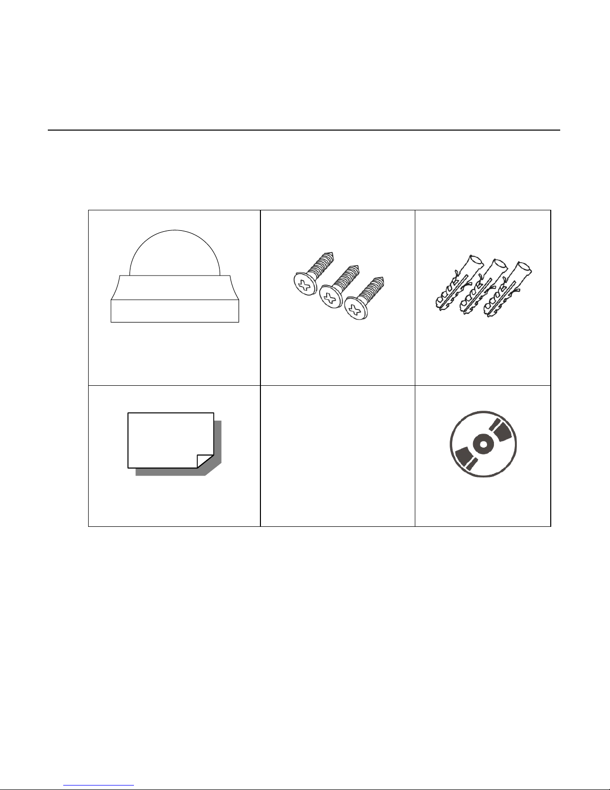
BOX CONTENTS
Before proceeding, please ch e ck that the box contains the items listed here. If any item is
missing or has defects, DO NOT ins tall or operate the product and contact your dealer for
assistance.
Camera
Self Tapping Screws Plastic Anchors
Quick Start Guide CD
Page 12
12
CAMERA OVERVIEW
Before installing or connecting the dome camera, please refer to this section and complete
preparations for dome setup and all switch settings.
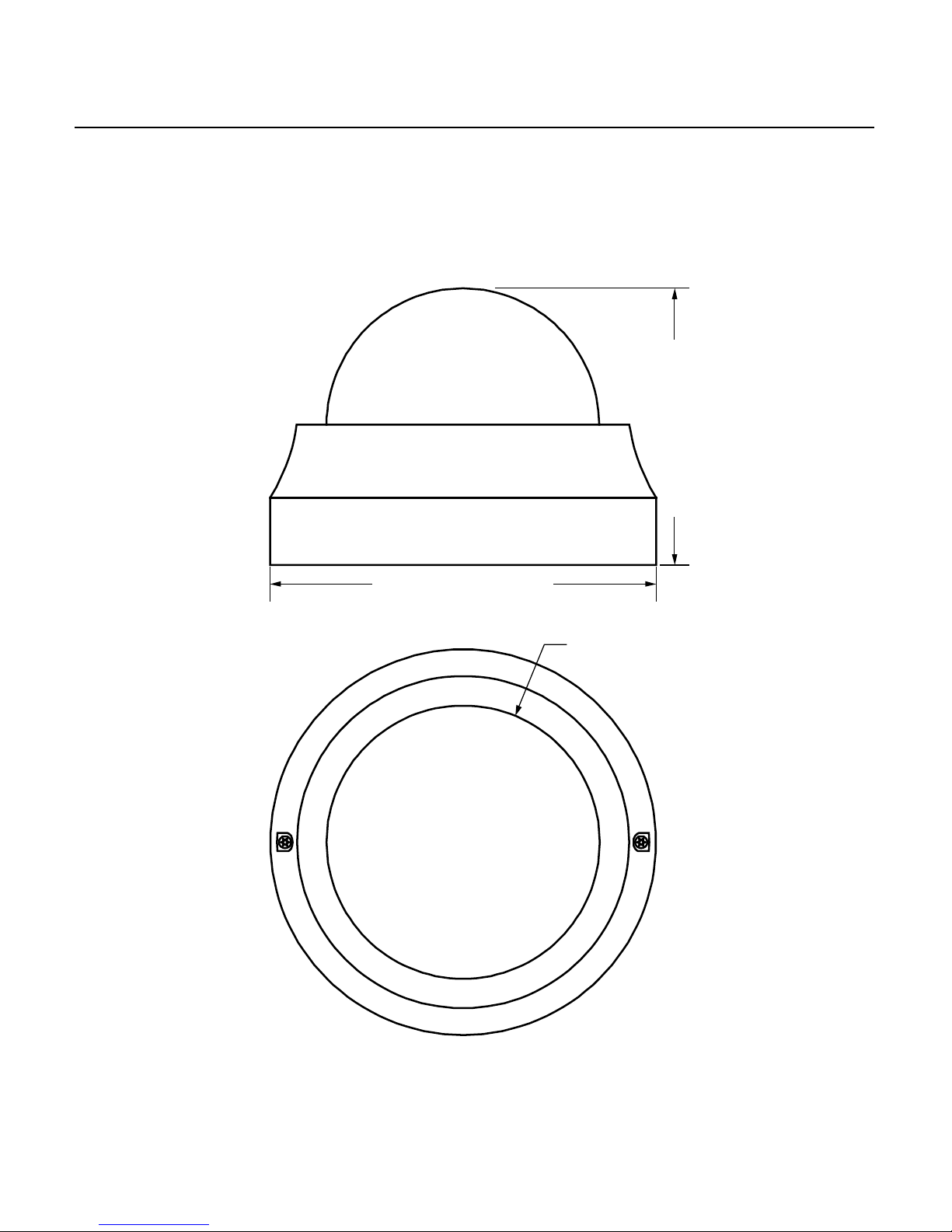
Dimensions
• Diameter – 110.21mm (4.3 inches)
• Height – 47.66mm (1.87inches)
4.625” (117.5 mm)
3.375” (85.73 mm)
Ø 3.125” (79.38 mm)
Page 13
32700AA 13
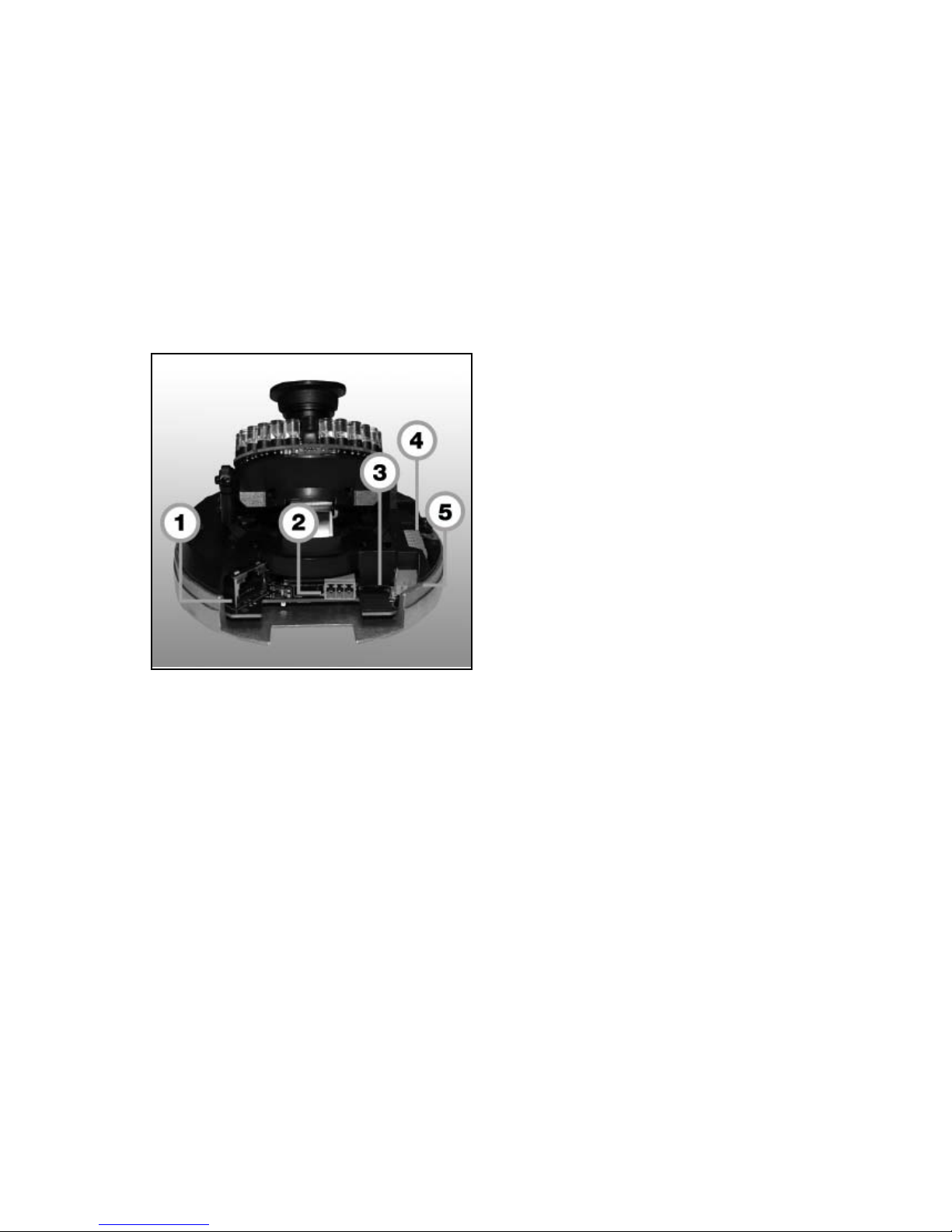
Connections
The Indoor Tamper Resistant IP Dome Cameras use Power over Ethernet (PoE) to power
the cameras. The only connection on the camera is the RJ45 Ethernet connector located
on the rear of the camera. Connect one end of the Ethernet cable to the RJ45 port on the
camera and the other end to power sourcing equipment (PSE) like a hub or router.
Check the status of the network connection by looking at the link indicator and activity
indicator LEDs. If the LEDs are not lit check your network connection. The green link LED
indicates a network connection and the orange activity LED flashes to indicate network
activity.
1 Network RJ45 Ethernet cable
2 Power For 12V DC or 24V AC power
3 Micro SD Card For on-board video storage
4 Alarm I / O Alarm connection
5 BNC Video BNC video connection
Page 14

14
Reset Button
Push the reset button to return the c amera to factory default settings.
Alarm I/O Diagram
1 Alarm In (-) Alarm Connection
2 Alarm In (+)
3 Alarm Out (-)
4 Alarm Out (+)
5 Alarm Out (L) Line Out
6 Alarm Out (R)
7 GND
8 Audio In Line In
1
2
3
4
5
6
7
8
Page 15

32700AA 15
LOCATE CAMERA
OPENEYE NETWORK CAMERA MANAGER
Use the included Network Camera Manager software to easily find your network cameras
for initial setup. The OpenEye IP Finder software is included on the CD with all OpenEye
IP devices.
Installation
You can install Network Camera Manager on any personal computer (PC) or laptop using
the software CD included with your OpenEye IP camera or by downloading the program
from openeye.net.
Note Network Camera Manager will only work on PCs or laptops that use a Windows
operating system. It is compatible with Windows XP, Vista, 7, and 8.
Starting Network Camera Manager
After installing the program on your PC or laptop, open the program to begin configuring
your cameras.
To access Network Camera Manager on an OpenEye recorder, you must operate the
recorder in Windows Mode.
1. In the Live Screen, click Exit.
2. Click Restart in Windows Mode.
3. Click OK.
4. Double-click Network Camera Manager.
Page 16
16
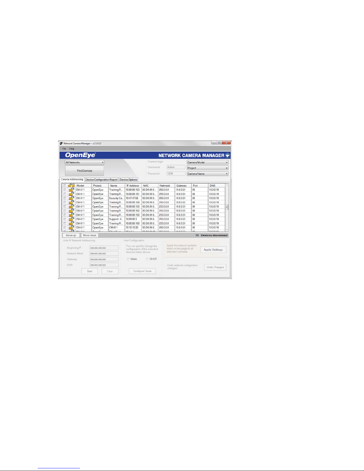
Device Addressing
The functions on the Device Addressing tab allow you to find, configure, and view network
cameras.
Finding Network Devices
1. Click Find Devices on the Device Addressing tab.
2. To narrow your search by Camera Model, Project, or Camera Name, select
your desired criteria from the appr opr iate li sts.
Page 17
32700AA 17
SETUP & CONFIGURATION
CONNECTING TO THE CAMERA
1. Locate the camera on the IP Finder list.
2. Double-click the camera to open the Viewer software in your web browser.
3. Log in to the camera with the appropriate User Name and Password.
Note The default User name is Admin and the default Password is1234. The
username and password are case sensiti ve
Resetting the Camera
If it is necessary to reset the camera to the factory default settings, hold down the Reset
button (see Camera Overview for 30 seconds . This will return all settings, including
network setup, to the factory default. The IP address of the camera will return to
192.168.0.250.
Administrator/User Privileges
The Administrator account has the authority to configure the IP camera and authorize
users’ access to the camera. The User accounts have access to the camera with limited
authority.
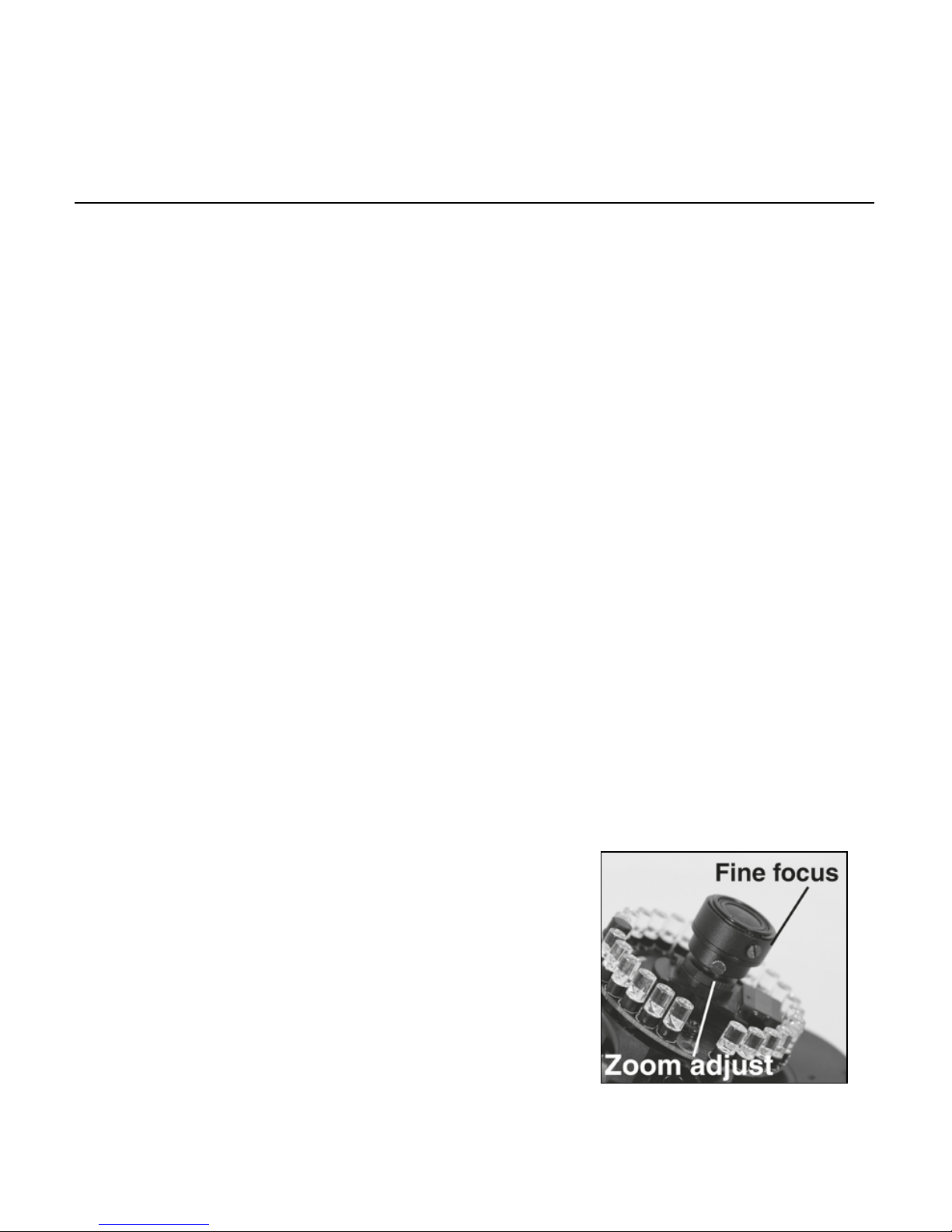
Lens Adjustment
The Viewer software will display an im age from the camera on the Home tab. Adjust the
camera’s focus to produce a clear image.
1. Remove the screws from the camera dome
cover.
2. Remove the rubber guard from the lens.
3. Loosen the zoom and fine focus lens screws.
4. Turn the lens to focus your camera.
5. Tighten the zoom and fine focus lens screws. Do
not overtighten.
6. Replace the rubber guard.
Page 18
18
Connecting a Stream
OpenEye IP cameras are optimized for use with OpenEye recorders, but you can also
connect to your OpenEye IP camera s using third party software like VLC media player
(http://www.videolan.org).
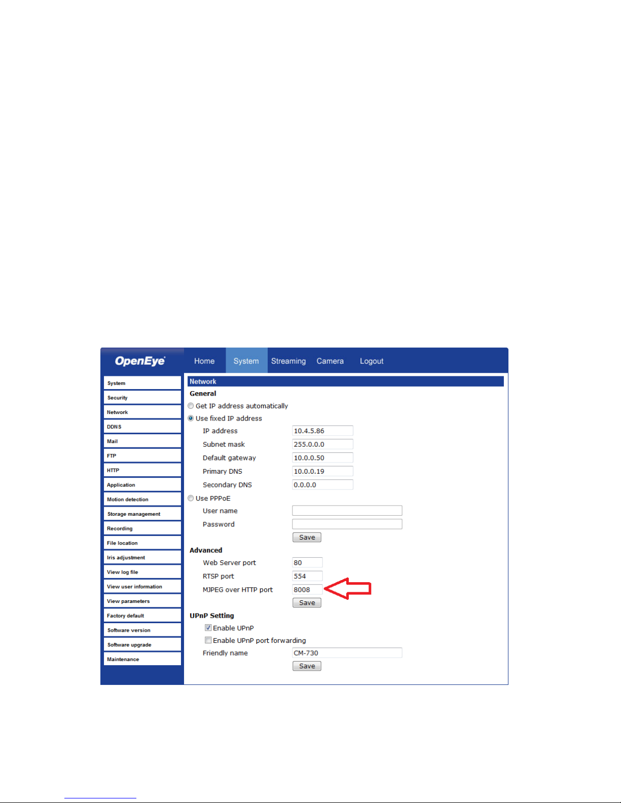
To connect the camera you may need to provide the stream URL. All OpenEye IP
cameras are capable of delivering two RTSP streams, as well as streaming MJPEG over
HTTP. The stream URLs are listed below.
rtsp://<ip address>/m jpe g
rtsp://<ip address>/m peg 4
rtsp://<ipaddress>/h264
http://<ipaddress>:8008
The MJPEG over HTTP stream is identified by a port number. The default port is 8008;
this port can be configured in the cameras Network page:
Page 19

32700AA 19
Connecting Over the I nt er net
There are some challenges with connecting to OpenEye IP cameras over WAN (internet)
connections because the camera streams video over RTSP. RTSP is an excellent
protocol for media and is now used on many IP cameras (including OpenEye) as the
default streaming option.
However, RTSP is not suitable for transmission between two locations that are behind
different routers. In this case, the client (for example, the OpenEye HVR or NVR server
software) connects to the camera, then requests a stream. The camera uses that
connection to return a stream, but si nce the connection originated on the client side and
has now switched to the camera (remote) side, the router does not have any way to
determine where the traffic should be routed, so no video appears at the recorder.
There are three solutions to this:
1. Connect modems on both sides directly to the recorder and camera. If there is no
router, no network address translation is needed.
2. Use routers with VPN support and set up a small VPN. Once this is done, the traffic
will be treated as though it were all on the local network.
3. (Best solution) – Use router s with connection tracking. This is quite easy; VOIP
also uses RTSP and faces the same challenges. If a router is marketed as having
“VOIP Support”, it will have the necessary connection tracking capability to allow any
type of RTSP communication (not just VOIP).
With proper planning and the correct equipment, RTSP cameras CAN stream over the
WAN to a recording device for minimal additional cost and labor.
Please contact OpenEye support if you require any additional information on these topics.
Page 20

20
VIEWER SOFTWARE
To access the setup menu, you need to install the viewer software on your PC or recorder.
The viewer software will install automatically the first time you connect to the camera. If
your internet browser doesn’t install the viewer software, check the security settings or
ActiveX controls and plug-in settings. If your internet browser asks for permission to install
the ActiveX control, you must allow the ActiveX control to continue the installation.
The first time you connect to a camera, the browser will ask for permission to install the
ActiveX Control necessary to display the camera video. Right-click the information bar and
click Install ActiveX Control to allow the installation.
Note IP camera audio is only available on the Indoor IP mini dome camera. The Talk
button will not be available on the Outdoor version of the camera.
Viewer Tabs
Home – Monitor live video.
System – Set the host name, system time, root password, and network related settings.
(Admin access only)
Streaming – Modify the video resolution and select the audio compression type.
Camera – Adjust the camera parameters inc luding Exposure, White Balance, Brightness,
Sharpness, Contrast, and Digital Zoom.
Logout – Change user.
Page 21

32700AA 21
Home
Screen Size Adjustment – Click the screen size buttons to adjust image display size x1/2
and full screen.
Digital Zoom Control – In full screen m ode, right-click to activate digital zoom and use
the scroll wheel to zoom in/out.
Talk – Talk allows the local site to talk to the remote site. This function is only available to
Users who have been granted this privilege by the Administra t or.
Listen – The speaker function allows the loc al site to listen to the remote si te. This
function is only available to users who have been granted this privilege by the
Administrator.
Note The Talk and Listen functions are only available on the Indoor IP mini dome
camera. The Talk button will not be available on the Outdoor version of the
camera.
Page 22

22
Snapshot – Click the button, and a JPEG snapshot will automatically be saved in
the appointed place. The default location is: C:\.
Note If you are using Windows Vista or 7, you will need to change the Snapshot
location. Windows UAC does not allow i nternet programs to write directly to C:\
for security reasons.
Record – Click Record to star recording live vi deo. Click Record again to stop recording
video. Recorded video will be saved automatically to the designated location on the local
workstation. The default location is C:/. This location can be changed in File Location, in
the System menu.
Note If you are using Windows Vista or 7, you will need to change the video clip
location. Windows UAC does not allow i nternet programs to write directly to C:\
for security reasons.
Page 23

32700AA 23
System
Note The System tab is only accessible by the Administrator.
System
Host Name – The Host Name is used to identify the cam era on your system. If camera
based Motion Detection is enabled and is set to send alarm message by Mail/FTP, the
host name entered here wi ll display in the alarm message.
Time Zone – Select your time zone.
Enable Daylight Saving Time – Select this option to enable daylight saving time, and
then select the offset, start and end dates and times.
Time Format – Select your de sired time format.
Sync With Computer Time – Select to synchronize t he cam era date and time with the
connected recorder.
Manual – Set video date and time manually.
Sync with NTP server – Network Time Protocol (NTP) is an alternate way to synchronize
your camera’s clock with a NTP server. Specify the server you wish to synchronize in the
NTP Server box. Then select an Update Interval. For more information about NTP, visit
www.ntp.org.
Page 24

24
Security
Admin Password
To change the administrator password, type a new password in the Admin Password box
and confirm below.
Note The maximum length of the password is 14 characters. The following char acter s
are valid: A-Z, a-z, 0-9, !#$%&’-.@^_~.
Page 25

32700AA 25
Add User
The user name and pas swords are limited to 16 characters. T here is a max imu m of twenty
user accounts
1. Type the new User name and Password
2. Select the appropriate check boxes to give the user Camera Control, Talk and Listen
permissions.
I/O Access – Basic functions that enable users to view video when accessing to the
camera.
Camera Control – Allow s the User to change camera param et ers on the Camera tab.
Talk/Listen – Talk and Listen f unct ion s allow the user at the local site (DVR) to
communicate with, the administrator at the remote site.
3. Click Add.
Delete User
1. Select the user name on the User Name list under Manage User.
2. Click Delete to remove the user.
Edit User
1. Select the user name on the User Name list under Manage User.
2. Click Edit to edit the user password and permissions.
3. Type a new password or the existing pas s word in the User password box.
Note You must type a password in the User password box to make any changes to
an account.
Note For security reasons, every time the user properties are opened the access
check boxes are automatically cleared. Make sure you select any user access
options each time you edit the user properties.
Page 26

26
Network
You can choose to use a fixed IP address or a dynamic IP address (assigned by a DHCP
server or router) for the camera.
Get IP address automatically (DHCP)
The camera comes preconfigured with a fixed IP address, selecting Get IP address
automatically requires a router or DHCP server to assign an IP address to the camera.
Note Every network device has a unique Media Access Control (MAC) address that
can be used for identification. The MAC address is located on the bottom of
each camera, and on the box label (OpenEye Network Camera Manager also
displays the MAC address for identification). Record your camera’s MAC
address for identification in the future.
Page 27

32700AA 27
Use Fixed IP Address
To set up a new static IP address:
1. Select the Use fixed IP address option.
2. Type a new IP address in the IP address box.
3. Type a new address in the Default Gateway box.
4. Click Save to confirm the new setting.
When using static IP address to log in to the IP Camera, you can access it ei ther through
OpenEye IP Finder software or type the IP address directly in the address bar of your
Internet Explorer.
General
• IP address – The IP Address is necessary for network identification.
• Subnet mask – Used to determi ne if the destination is in the same subnet. The
default value is 255.255.255.0.
• Default gateway – Used to forward frames to destinations on different sub nets or for
internet access.
• Primary DNS – The primary domain name server that translates hostnames into IP
addresses.
• Secondary DNS – A secondary domain name server that backups the primary DNS.
Advanced
• Web Server port – Defines the port that Internet Explorer uses to connect over the
web and view video. If this port is changed then the new port must be defi ned when
attempting to web connect (ex: if your camera’s IP address is 192.168.0.100 and you
change the web port to 8001, then you must type http://192.168.0.100:8001 in your
browser).
Note This is also the port used in OpenEye Server Software.
• RTSP port – The default RTSP port is 554; setting range: 1024 ~65535.
• MJPEG over HTTP port – The default HTTP Port is 8008; setting range: 1024
~65535.
• HTTPS port – The default HTTPS Port is 443; setting range: 1024 ~65535.
Note No port number can be used in duplication on more than one item.
IPv6 Address Configuration
To enable IPv6 selec t Enable IPv6 and click Save. See your network administrator if you
are unsure of your network configuration.
Page 28

28
QoS (Quality of Service)
Quality of Service al lows you to prioritize network traffic services of the camera’s
functions. The QoS function utilizes the Differentiated Services prioritized using Codepoint
values (DSCP).
Note Routers and switches on the network must be QoS or DSCP capable, and have
these settings enabled for this function to operate on your network.
DSCP Settings
The DSCP value range is 0 to 63. The default value is 0, which indicates the function is
disabled; and rates 1 as the highest priority, and 63 as the lowest priority.
• Video DSCP: prioritize video streaming over HTTP or RTSP
• Audio DSCP: prioritize aud io strea min g
• Management DSCP: prioritize web interface traffic over HTTP
SNMP
With Simple Network Management Protocol (SNMP) enabled, the camera can be
monitored and managed remotely with a network management system. Contac t your
network administrator if you are not familiar with SNMP setup.
SNMP v1/v2
• Enable SNMP v1
• Enable SNMP v2
• Read Community: Specify the community name that has read-only access.
• Write Community: Specify the community nam e that has read/write access.
Traps for SNMP v1/v2
Traps are used to send a message to the network management system for important
events or status changes.
• Enable Traps: enables trap reporting
• Trap Address: enter the IP address of the network management system
• Trap Community: enter the community to use when sending trap messages
Page 29

32700AA 29
UPnP (Universal Plug and Play)
• Enable UPnP: When enabled the camera will appear in My Network Places on
Windows computers running UPnP on the same network.
• Enable UPnP Port Forwarding: When enabled the camera will attempt to open the
web server port on the router automatically.
• Friendly Name: Set a name to easily identify the camera.
Page 30

30
DDNS
DDNS (Dynamic Domain Name Service) is a service that allows a connection to an IP
address using a hostname (URL) address instead of a numeric IP address. Most Internet
Service Providers use Dynamic IP Addressing that frequently changes the public IP
address of your internet conne ctio n; this means that when co nnec ting to the camera over
the internet, you need to know if your IP address has changed. DDNS autom atically
redirects traffic to your current IP address when using the hostname address.
• Enable DDNS – Select the check box to enable DDNS.
• Provider – Select a DDNS host from the Provider l ist.
• Host name – Type the registered domain name in the field.
• Username/E-mail – Type the username or e-mail required by the DDNS provider for
authentication.
• Password/Key – Type the password or key required by the DDNS provider for
authentication.
Page 31

32700AA 31
Mail
The camera can send an e-mail via Simple Mail Transfer Protocol (SMTP) when motion is
detected. SMTP is a protocol for sending e-mail messages between servers. SMTP is a
relatively simple, text-based protocol, where one or more recipients of a message are
specified and the message text is transferred. The configuration page is shown as follows:
Two sets of SMTP accounts can be configured. Each set includes SMTP Server, Account
Name, Password and E-mail Address settings. For SMTP server, contact your network
service provider for more specific information .
Page 32

32
FTP
The camera can send alarm message to a specific File Transfer Protocol (FTP) site when
motion is detected. You can assign alarm message to up to two FTP sites.
1. Type the FTP details, including server, server port, user name, password and remote
folder, in the appropriate boxes.
2. Click Save when finished.
Page 33

32700AA 33
HTTP
The camera can send alarm messages to a specific Hypertext Transfer Protocol (HTTP)
site when motion is detected or when the sensor input is activated. You can assig n alarm
messages to up to two HTTP sites.
1. Type the HTTP details, including server, user name and password, in the appropriate
fields.
2. Click Save when finished.
Page 34

34
Motion Detection
Motion Detection allow s the camera to detect motion and trigger alarms when the motion
level in the detected area exceeds the determined sens i tivity threshold value.
In the Motion Detection page, there is a motion detection window (red box) displayed on
the Live View Pane. The Motion Detection window defines the motion detection area. To
change the size of the Motion Detection window, drag the edge of the frame to resize.
You can add up to 10 motion detection windows.
• Click add under the Live View Pane to add a Motion Detection window.
• To delete a Motion Detection window, use the mouse to select the frame and click
delete.
Page 35

32700AA 35
When motion detection is activated, the Motion pop-up window will open.
When motion is detected, the signals will be displayed on the Motion window as shown
below.
Motion Detection
Turn motion detection on or off. The default setting is Off.
Motion Detection Setting
• Sampling pixel interval [1-10] – Default value is 10, which means system will take
one sampling pixel for every 10 pixels.
• Detection level [1-100] – Default detection level is 10. This item sets the detection
level for each sampling pixel; the smaller the value, the more sensitive it is.
• Sensitivity level [1-100] – The default sensitivity level is 80, which means if 20% or
more sampling pixels are detected as changing, the system will detect motion. The
bigger the value, the more sensitive it is. As the sensitivity value is increased, the red
horizontal line in the motion indication window will be lowered accordingly.
• Time interval (sec) [0-7200] – The default interval is 10. The value is the interval
between each detected motion event.
Page 36

36
Triggered Action
You can specify which actions the camera should take when motion is detected.
• Send Alarm Message by FTP/E-Mail – Select to send an alarm me ssa ge to a
configured FTP and/or E-Mail address w hen moti on is dete ct ed. When sending to
email, the alarm notification is text only. When sending to FTP, the alarm notification
will upload a text file to the FTP location.
• Upload Image by FTP – Select to assign an FTP site and config ure various
parameters as shown in the figure below. When motion is detected, event images will
be uploaded to the appointed FTP site.
Upload Image by E-Mail – Select to assign an e-mail address and configure various
parameters as shown in the figure below. When motion is detected, event images will be
sent to the appointed e-mail address.
Note Make sure SMTP or FTP configuration has been completed. See the Mail and
FTP sections for more information.
Page 37

32700AA 37
File Name – Enter a file nam e in the box, ex. image.jpg. The uploaded image’s file name
format can be set in this section. Please select the one that meets your requirements.
• Add date/time suffix
File name: imageYYMM DD_HHNN SS _XX.jpg
Y: Year, M: Month, D: Day
H: Hour, N: Minute, S: Second
X: Sequence Number
• Add sequence number suffix (no maximum value)
File name: imageXXXXXX X . jpg
X: Sequence Number
• Add sequence number suffix (limited value)
File Name: imageXX.jpg
X: Sequence Number
The file name suffix will end at the value entered in this box. For example, if the
setting is up to “10,” the file name will start from 00, end at 10, and then start all over
again.
• Overwrite – The original image on the FTP site will be overwritten by the new
uploaded file with a static filename.
Page 38

38
Storage Management
All OpenEye Tamper Resistant IP Mini Dome cameras include an integrated microSD™
card that can be used to record video or images. The card slot is compatible with a
microSD™ card up to 16GB.
Device Information – Displays the storage total size and free space information of the
included microSD™ card.
Device Setting – Allows you to format the microSD card.
Device Cleanup Setting – Use this feature to enable overwrite settings on the SD card.
The camera can remove files from the card after they reach a certain age, or when the
card is a certain percent full.
Recording List – Displays a list of files saved to the card. You can delete files from the
card, or save them to your local PC.
Note If you are using Windows Vista, 7, or 8, you will need to change the Snapshot
location. Windows UAC does not allow i nternet programs to write directly to C:\
for security reasons.
Page 39

32700AA 39
Recording
The recording schedule allows you to set up scheduled recording to the mic roSD™ card.
To set up continuous recording:
1. Select Always to continually record until the card is full.
2. To set the camera to overwrite old data, see the instructions for Disk Cleanup Setting
earlier in this section.
To set a recording schedule, follow these instructions.
1. Select Only During Time Frame.
2. Click the schedule you would like to c reate (1 ~ 10).
3. Select the days of the week for this schedule.
4. Type a Start Time and a Duration.
5. Click Save.
6. To create another schedule, click ano ther num ber in the Schedule list, and set your
parameters.
7. Click Save after each schedule is completed.
Page 40

40
File Location
The camera supports a JPEG snapshot function. You can specify a storage location for
snapshot images. The default location is: C:\.
Note If you are using Windows Vista, 7, or 8, you will need to change the Snapshot
location. Windows UAC does not allow i nternet programs to write directly to C:\
for security reasons.
Note Make sure the selected file path contains valid characters such as letters and
numbers.
Page 41

32700AA 41
Information
The Information page contains the System Log, User Information, and Parameter List.
System Log
Click System Log to view the system log file. The content of the file provides useful
information about configuration and connections.
Page 42

42
User Login Information
All users for the camera are listed under User information. The example below show that
the Admin password is 1234 and there is one user named User with the password 4321.
View User Privilege
Select a user account from the list and click get user priv acy to view the permissions for
the user account.
Page 43

32700AA 43
Parameter List
Click Parameter List to view the system parameter s ettings.
Page 44

44
Software Upgrade
Upgrading the Camera Viewer Software
Note Make sure the software upgrade file is available before starting the software
upgrade.
1. Click Browse and find the upgrade file.
Note Do not change the file name, or the system will fail to find the file.
2. Select the file name from the list under Step 2.
3. Click Upgrade. The sys tem will check to find the upgrade file, and then start to
upload the upgrade file. The upgrade status bar will display on the page. When it
reaches 100%, the viewer will return to Home page.
4. Close the internet browser.
5. Go to the Windows Control Panel and double-click Add or Remove Programs.
Locate the Camera Viewer software on the Currently installed programs list
and click Remove to uninstall the previous software version.
6. Open the internet browser again and log in to the camera. The system will
automatically download the new version of the Camera Viewer software.
Page 45

32700AA 45
Maintenance
On the Maintenance page you can export the cameras current configuration, or import the
configuration for a camera. Use the factory default page to reset the IP Camera to factory
default settings if necessary.
Note Do not import configuration files from different models of cameras.
Full Restore –To reset the IP camera to the factory default settings, including the defa ult
IP address, click Set Defau lt. The system will restart after 30 seconds. If you cannot
access the camera menu, you can return the camera to the factory default settings by
holding down the reset button on the camera connection board for 30 seconds. See Error!
Reference source not found. for the button location.
Reboot – To restart the IP camera without changing the current camera settings, Click
Reboot.
Export – You can save the system settings by exporting the configuration file (.bin) to a
specified location for future use. Click Export, then Save, and specify the desired
location.
Upload – To copy an existing configuration file to the IP camera, click Browse, select the
desired configuration file, then cli ck Upload.
Page 46

46
Video and Audio Streaming S e ttings
On the Streaming tab, the Administrator can configure specific video resolution, video
compression mode, video protocol, audio transmission mode, etc.
Video Format
Select the desired video resolution for the camera on the Video Format page. The
recorder will record video based on the resolution s el ected here.
Page 47

32700AA 47
Video Resolution
The camera provides four codec options under video resolution (two single streaming
options and two sets of dual streaming options):
• MJPEG only
• H.264 only
• MJPEG + H.264
• H.264 + H.264
Once a codec option is selected, multiple resolutions are available for each stream.
MJPEG Resolutions* H.264 Resolutions*
1920x1080 1920x1080
1920x1080 (@ 15 FPS)
1280x1024 1280x1024
1280x720 1280x720
1024x768 1024x768
800x600 800x600
720x480 720x480
640x480 640x480
352x240 352x240
*All resolutions are at 30 Frames Per Second (FPS) unless otherwise noted.
Note Due to resource management, some resolutions may be unavailable when
selecting a dual stream option.
Note Due to resource management, the Motion Detection, 3DNR, and Privacy Mask
functions are not available when using the H.264 Only codec option and
selecting the Low Latency H.264 format.
Text Overlay Settings
Text Overlay allows you to select text to be display over the video. Three options are
available: Date, Time, and a Custom String (up to 20 alphanumeric characters).
Page 48

48
Video Rotate Type
You can change the orientation of the video output if necessary.
Normal Video – This is the default rotation designed for a normal setup with the camera
mounted with the dome facing down.
Flip Video – This option will vertically flip the video image (without the intervention of
another device this m ay cause the reversal of perceived left and right when viewing the
image).
Mirror Video – This option will horizontally flip the video image (without the intervention of
another device this m ay cause the reversal of perceived left and right when viewing the
image).
90 Degree Clockwise – This option will rotate the video image 90 degrees to the right.
180 Degree Rotate – This option will rotate the video im age 180 degrees (this is the
option most commonly needed if the image appears upside-down when the camera is first
installed).
90 Degree Counterclockwise – This option will rotate the video image 90 degrees to the
left.
GOP Settings
The Group of Pictures settings allow you to modify the frame structure of the video
stream. This setting changes the frequency of the I-frames that occur within the stream of
P-frames (2~64). Increasing this number increases the number of P-frames between each
I-frame; decreasing the file size of the stream, but increasing the risk of video decoding
errors. Decreasing this number decreases the number of P-Frames between each I-frame;
increasing the file s i ze of the stream, but decreasing the risk of video decoding errors.
H.264 Profile
The H.264 Profile may need to be changed if you are us i ng a third party recorder that is
not capable of decoding H.264 Main Profile video compression. Select the com pat ible
compression type for each stream if nece ssar y .
Page 49

32700AA 49
Video Compression
You can se lect an MJPEG/H.264 compression mode on the video compression page
appropriate for your application. You can also select to display compression information
on the Home page.
MJPEG compression settings include:
• high compression, low bitrate, low quality
• middle compression, default
• low compression, high bitrate, high quality
H.264 compression setting s incl ude:
• 1024kbps, highest compression, l owest quality
• 2048kbps
• 4096kbps, middle compressi o n, default
• 6144kbps
• 8192kbps, low compression, highest quality
CBR Mode Setting
• The Constant Bit Rate mode allows you to lock in the bit rate of the H.264 stream. If
this setting is not enabled bit rate may fluctuate based on available bandw idth.
Page 50

50
Hot Spot
The Hot Spot feature allows you to transmit different parts of the camera image on
separate streams. Each stream is displaying a portion of the image at the full size of a
regular image. This is useful for focusing on details in different areas of a single camera
view.
1. On the Video Format screen, set the Video Resolution to transmit at least three
streams, and then cl ick Save.
Note The Hot Spot feature will only function when the camera is set for multiple
streaming at 3 or more stream s.
2. Click Hot Spot.
3. Select Enable H.264-2 Hot Spot to add a selection area. Click and drag the
selection rectangle to the desir ed posit ion and siz e.
4. Click Save.
5. Repeat for any other Hot Spots you want to enable.
Page 51

32700AA 51
Video OCX Protocol
On the Video OCX protocol page, you can select different protocols for streaming media
over the network. In the ca se of multi ca st networking, you can select the Multicast mode.
Video OCX protocol s etting options include:RTP over UDP
• RTP over UDP
• RTP over RTSP(TCP)
• RTSP over HTTP
• MJPEG over HTTP
Select a mode accordi ng to your data delivery requirements. If you are transmitting over
the internet using a router and port forwarding, you will need to use RTP over RTSP
(UDP). You will also need to forward the RTSP port to the camera (see the network setup
page to find the RTSP port).
Multicast Mode
1. Enter all required data, including multicast IP address, H.264 video port, MJPEG
video port, audio port and TTL into each box.
2. Click Save to confirm the setting.
Page 52

52
Frame Rate Control
Setting the camera to transmit fewer frames can save bandwidth. Use the Frame Rate
Control screen to adjust the frame rate of each stream.
Each of the MJPEG and H.264 streams can have a separate frame rate setting from 1 to
30 frames per second.
Note Higher frame rate will increase video smoothness, as well as file size and
bandwidth usage.
Note Lower frame rate will decrease v ideo smoothn es s, as well as file size and
bandwidth usage.
Page 53

32700AA 53
Video Mask
You can use the video mask page to define a privacy mask to keep users from viewing
parts of the image.
You can enable up to five privacy masks and choose a color to obscure the live view from
users.
Page 54

54
Audio
On the Audio page, you can selec t an audio transmission mode and audio bit rate.
Note Audio monitoring and recording laws vary from location to location. It is highly
recommended that you consult your local, state and federal laws to verify that
you are in compliance before implementing audio recording.
Transmission Mode
• Simplex (Listen only) – The local/remote site can only listen to the other site.
• Disable – Turn off the audio transmission function.
Server Gain Settings
Set the audio input/output gain levels for sound amplification. The audio gain values are
adjustable from 1 to 6, and will be turned off if ‘Mute’ is selected.
Page 55

32700AA 55
Bit Rate
Selectable audio transmission bit rates include the following:
16 kbps (G.726) 40 kbps (G.726)
24 kbps (G.726) uLAW (G.711)
32 kbps (G.726) ALAW (G.711)
Both uLAW and ALAW signify 64 kbps, but in different co mpr ess ion form ats. A higher bit
rate will provide higher audio quality and require more bandwidth.
Page 56

56
Camera
Exposure
The exposure is the am ount of light received by the image sensor and is determined by
the width of lens diaphragm opening (iris adjustment), the amount of exposure by the
sensor (shutter speed) and other exposure parameters. When you have made your
changes, click Set in the Exposure section.
Auto Mode
• In Full Auto mode, the camera’s Shutter Speed, IRIS and AGC (Auto Gain Control)
control circuits work together automatically to set a consistent video output level. Max
Gain can be adjusted between 1 ~ 3, or turned Off. The Min Shutter Speed is
adjustable from 1/500 to 1 second.
Manual Mode
• In Manual Mode, you can select the shutter speed and set the gain. The shutter
speed range is from 1/10000 to 1 second. The Gain can be adjusted between 1 ~ 9,
or turned Off.
Page 57

32700AA 57
White Balance
A camera needs to find reference color temperature, whic h is a way of measuring the
quality of a light source, for calculating all the other colors. The unit for measuring this
ratio is in degree Kelvin (K). Users can select one of the White Balance Control modes
according to the operating environment. The following table shows the color temperature
of some light sources for reference. When you have made your changes, click Set in the
White Balance section.
Light Source Color Temperature in K
Cloudy Sky 6,000 to 8,000
Noon Sun and Clear Sky 6,500
Household Lighting 2,500 to 3,000
75-watt Bulb 2,820
Candle Flame 1,200 to 1,500
Auto Mode
In Auto mode, white balance works within its color temperature range and calculates the
best-fit white balance.
ATW Mode (Auto Tracing White Balance)
In ATW mode, the camera removes the signals within a range of 2000K to 10000K, which
helps to even out the bright white portions of the image.
One Push
One Push balances color temperature based on a white object within the viewing area.
Follow these instructions to use One Push white balancing.
1. Place a white object in the viewing area of the camera. A white piece of cards tock is
the best option.
2. On the camera viewing software, click One Push, and then click Set.
3. Click the button to adjust the color tem perature based on the white object.
4. Click Set again to save your settings.
Manual Mode
In Manual mode, you can change the White Balance value manually by a specifying the R
gain and B gain; the R/B gain range is fr om 0 to 255.
Page 58

58
Picture Adjustment
Adjust your image quality in the Picture Adjustment section. When you have made an
alteration to any of the following settings, click Set to save your changes .
Brightness
Adjust the image’s brig htne ss on the camera. The Backlight value is adjustable from -12
(dim) ~ +15 (brightest).
Sharpness
Increasing the sharpness level can make the image looked sharper; it especially
enhances an object’s edge. The value of sharpness is adjustable from 0 ~ +15 (sharpest).
Contrast
Correct the contrast of the entire image by adjusting the Contrast level, ranging from -6 ~
+19.
Saturation
Adjust the saturation of color components in an image through the Saturation function,
which is adjustable from -6 ~ +19.
Hue
Adjust the hue of color components in an image with the Hue function, which is adjustable
from -12 ~ +13.
Backlight
Backlight compensat i on can c orrect for overly -bright backlit scenarios, which can occur if
a camera is facing a door or window. Select On or Off for Backli ght compensation. Click
Set when you have made your choice.
Digital Zoom
You can choose to transmit an enlarged image from your camera, from x2 ~ x8. Click Set
when you have made your choice.
Page 59

32700AA 59
IR Function
Set your IR functions according to your needs.
Day/Night Function
Choose between Auto, Night, Day, Light Sensor, Light On, Light Off, and Smart settings.
IR Light Compensation
Enable or disable the camera to compensate for the IR illuminators.
D-WDR Function
Digital Wide Dynamic Range can even out lighting differences between areas of extreme
light and extreme shade. Select your desired D-WDR level (Low, Mid, High, or Off), and
then click Set.
Noise Reduction
Adjust your level of Noise Reduction as necessary, and then cl ick Set.
TV System
Select your transmission type (NTSC or PAL), and then click Set.
Logout
Click the Logout tab to change users.
Page 60

60
Digital Zoom
You can choose to transmit an enlarged image from your camera, from x2 ~ x8. Click Set
when you have made your choice.
3DNR/2DNR
These options allow you to adjust your noise reduction (Low, Middle, High, or Off).
Digital Stabilization
Enable Digital Stabilization to allow the camera to compensate for conditions in which i t
may move, such as when mounted on a pole.
Logout
Click the Logout tab to change users.
Page 61

32700AA 61
SPECIFICATIONS
CAMERA SPECIFICATIONS
Model
OE-C6412-R
Indoor / Outdoor
Indoor
Image Sensor
1/2.8” CMOS
IP Rating
-
Type / Format
H.264 / MJPEG
Wide Dynamic Range
Digital WDR
Minimum Illumination
0.0 Lux with IR LEDs engaged
Day / Night
True Day / Night
Resolution
30 IPS @ 1080P [1920 x 1080 / 2MP]
30 IPS @ 1280 x 1024 (1.3MP)
30 IPS @ 720P [1280 x 720 / 1MP]
30 IPS @ D1 [720 x 480]
30 IPS @ CIF [352 x 240]
Service Monitor Jack
No
Focal Length
3 ~ 6 mm
Iris Control
Fixed
White Balance
Manual / Manual / ATW
Auto White Balance
Range
Auto: 2700 ~ 8000K
ATW: 2450 ~ 10500K
Backlight
Compensation
On / Off
Auto Gain Control
Auto
Operating Temp
14°F~ 122°F (-10°C ~ 50°C)
Heater
No
Power Consumption
8.3W
Page 62

62
Model
OE-C6412-R
Input Voltage
12vDC / 24vAC / PoE
Weight
0.73 lbs (330 g)
Dimensions
Ø4.625" (117.5 mm) x H: 3.125” (79.375 mm)
Housing / Dome
Cover
White / Clear
IP SPECIFICATIONS
Model OE-C6412-R
Video Compression H.264 / MJPEG
Multi Streaming Quad Streaming
Audio In 1
Audio Out 1
Alarm In 1
Alarm Out 1
User Account 20
Page 63

32700AA
www.openeye.net
1-888-542-1103
© 2014 OpenEye
All rights reserved. No part of this publication may be reproduced by any means without written
permission from OpenEye. The information in this publication is believed to be accurate in all
respects. However, OpenEye cannot assume responsibility for any consequences resulting from
the use thereof. The information contained herein is subject to change without notice. Revisions or
new editions to this publication may be issued to incorporate such changes.
 Loading...