

Page 1

Digi-3-Coder
(Hot Foil Printer)
INSTALLATION DETAILS
OPERATOR INSTRUCTIONS
PARTS LISTING
CIRCUIT DIAGRAMS
Designed and manufactured by:
OPEN DATE EQUIPMENT LIMITED
UNITS 8 & 9 PUMA TRADE PARK
145 MORDEN ROAD
MITCHAM
SURREY
CR4 4DG
UNITED KINGDOM
Tel: 0044 (0) 208 655-4999
Fax: 0044 (0) 208 655-4990
Email: [email protected]
Web site: www.opendate.co.uk
Digi-3-Coder (Issue 1.2) 6 October 2005 Page 1
Page 2

Digi-3-Coder Index
Description Page
Index 2
Safety Instructions 3
Declaration of Conformity 4
Operating Specifications 5
Installation Procedures 6
Standard Frame Installation 7
Pneumatic Installation Details 8
Electrical Installation Details. 9
Fault And Print Relay Connections 10
Low Air Pressure Connections 11
Solenoid Valve Details 12
Getting Started, Operating Instructions
Initial Setting Procedures 13 - 14
Membrane & LED’s Layout 15
Operator Controls 16
System LED’s & Faults 17
Threading Diagram 18
Operator Instructions 19
Mechanical Fault Finding 20
Print Quality Deterioration 21
Technical Information
Main Circuit Board Connections 22
Wiring Details Plug on Printer 23
Connections Box PCB 24
Wiring Details Connection Cable 25
Dip Switch Settings & Explanations 26
Digi-3-Coder Dimensional Drawing 27
Cassette Spare Parts Drawing 28
Cassette Spare Parts Listing 29
Printer Body Spare Parts Drawing 30
Printer Body Spare Parts Listing 31
Connection Box Spare Parts Drawing 32
Connection Box Spare Parts Listing 33
Cylinder Assembly Spare Parts Drawing 34
Cylinder Assembly Spare Parts Listing 35
Recommended Spares Listing 36
Type Holder Details 37
Foil Sensor Instructions 38
Calibration Method 39
Machine Serial No. Identification. 40
Airborne Noise Emissions. 41
Warranty 42
Open Date Group Companies & Agents. 43
Digi-3-Coder (Issue 1.2) 6 October 2005 Page 2
Page 3

IMPORTANT SAFETY INSTRUCTIONS
1. Read these instructions carefully. Follow all warnings and instructions marked on the product.
2. Always disconnect the printhead and controller from the mains electricity and air supply before
attempting to clean or service it.
3. Never operate the printhead unless it is installed within the mounting frame supplied. When installed
correctly, the gap between the printer and print base should not be greater than 5mm. (see page 7)
4. Do not use the product near water. Never spill liquid of any kind on to the product.
5. Do not place this product on an unstable stand, table or machine. It may fall causing serious damage to
the product or injury to the operator.
6. Never insert objects of any kind into this product through any openings or gaps as they may touch
dangerous voltage points or short circuit parts that could result in fire or electric shock.
7. This product should only be operated from the type of electrical supply as indicated on the side guard of
the printer. (see page 5 & 39)
8. Ensure that the printhead connection cable is fully secured to the printer, with the bayonet connector
fully locked in place. Failure to do this will result in the machine not being properly earthed.
9. Use only the power cable supplied with the product. The cable supplied is three core mains cable,
utilising one wire as a grounding conductor. This must be connected to a suitable earth point at the
electrical supply. This is a safety feature. If any doubt arises in trying to connect the power cable, please
contact the manufacturer or agent who supplied the product.
10. Do not allow anything to rest on the power cable. Do not locate the product where persons will walk on
the cable.
11. If an extension cable is used with this product, make sure that the total ampere ratings of the equipment
plugged into the extension cable does not exceed the extension cable ampere rating. Also make sure
that the total rating does not exceed the fuse rating.
12. Do not service this product yourself as opening or removing guards may expose you to dangerous
voltage points, major burns and other risks. Refer all servicing to qualified personnel.
13. Do not attempt to use to use this product in areas where explosive gases or substances are present.
14. Once the product is under normal working conditions, care must be taken when removing the type
holder as you can easily burn yourself. There is a yellow warning sign on the type holder access door
indicating a danger. Open the door by gripping it at the side. The type holder can get very hot, it should
only be held by its plastic handle. Never touch the metallic parts, as temperatures could be as high as
220 degrees C.
15. Disconnect the product from the electrical and air supply, referring to servicing by qualified personnel
under the following conditions.
a. If the power cable is damaged or frayed.
b. If the air pipes are damaged in any way.
c. If liquid has been spilled into or if the product has been exposed to rain or water.
d. If the product does not operate normally when the operating instructions are followed. Adjust
only those controls that are covered by the instructions. Improper adjustment may result an
damage needing qualified technicians to restore the product to normal operating conditions.
Digi-3-Coder (Issue 1.2) 6 October 2005 Page 3
Page 4

EC DECLARATION OF CONFORMITY (Passed EMC Tests, September 2005)
We hereby declare that the following machinery complies with the essential health and safety
requirements of the Machinery Directive 98/37/EC, and the Low Voltage Directive 73/23/EEC
and its amendments, and the requirements of the Electromagnetic Compatibility Directive
89/336/EEC and its amendments.
Machine Description: Hot Foil Printer.
Model: Digi-3-Coder
Type: .....................
Serial number: .....................
Manufactured by: Open Date Equipment Limited.
Address Units 8 & 9, Pum a Trade Pa rk,
145 Morden Road,
Mitcham,
Surrey. CR4 4DG
United Kingdom.
The following transposed harmonised European standards have been used.
BS EN ISO 12100: part 1, 2003. Safety of machinery. Basic concepts, general principles for
design. Basic terminology, methodology.
BS EN ISO 12100: part 2, 2003. Safety of machinery. Basic concepts, general principles for
design. Technical principles.
EN294: 1992. Safety of machinery. Safety distances to prevent danger zones being reached by the
upper limbs.
BS EN 563:1994.
Safety of machinery. Temperatures of touchable surfaces. Ergonomics data to
establish temperature limit values for hot surfaces
.
EN60204: part 1, 1997. Safety of machinery. Electrical equipment of machines. Specification for
general requirements.
Emissions Tests
Generic Standard: EN61000-6-3:2001.
Including Conducted Emissions, Radiated Emissions,
Harmonics & Voltage Flicker.
Immunity Tests
Generic Standard: EN61000-6-1:2001.
Including Electrostatic Discharge, Radiated
Immunity, Fast Burst Transients, Surge Immunity, Conducted RF Immunity, Magnetic Immunity & Voltage
Dips.
FCC Part 15 Verification , Class A. Conducted and Radiated Emissions.
In addition, this machinery has been de signed a nd ma nufactu red in accor dance with:-
PD 5304:2000, Safe use of machinery.
A technical construction file for this machinery is retained at the above address.
Signed:
............................................ Date: ...........................................
Name K.F. Wingfield. Position Service Manager
Signing on behalf of the manufacturer.
Digi-3-Coder (Issue 1.2) 6 October 2005 Page 4
Page 5

Operating Specifications for Digi-3-Coder
Supply Voltage (Autosensed)
Nominal 230v AC, plus or minus 10% tolerance (207 – 253). 50 or 60 Hertz.
Nominal 115v AC, plus or minus 5% tolerance (109 – 121). 50 or 60 Hertz.
Heater
Single Cartridge Heater, 240 Volt AC, 500 Watt. (Part No. HEA 312070)
Normal temperature range: 70ºC to 220ºC, or 158ºF to 428ºF
Thermistor
Model No. USP5362 (Part No. THE 312080)
Output Relay Contacts
Fault Relay:- Rated at 24V DC, 1 amp current.
Print Relay:- Rated at 24V DC, 1 amp current.
(Both relays utilise common, normally open or normally closed contacts)
Input Print Signals
Voltage Free contacts. (microswitch, relay or plc etc.)
Voltage 10 – 30 Volts AC or DC (polarity unimportant)
Microprocessor
PIC Micro-Processor type:-.
Controlled by a specific designed membrane panel with inbuilt switches etc.
The temperature display is seen through a translucent panel on the membrane.
Solenoid Valve Output
24 Volt DC, 80mA current normally. (Part No. VAL 312034)
Air Pressure required
4.0 to 6.8 bar
Air Consumption
231cc @ 6.8 bar free air per cycle.
Foil Capacity
153 Metres (500 feet)
Foil Indexing
2mm to 16mm in 0.1mm increments. (0.078" to 0.625" in 0.005” Increments)
Dwell Time
10 to 2000 milliseconds.
Print Signal Delay
0 to 999 milliseconds. (Indicated by flashing green LED if activated)
Digi-3-Coder (Issue 1.2) 6 October 2005 Page 5
Page 6

Digi-3-Coder Installation Procedures
Digi-3-Coder (Issue 1.2) 6 October 2005 Page 6
Do not connect the mains supply until you have ensured that correct voltage is being
supplied. (See page 5, Operating Specifications)
If the printer is fitted to a stand alone bracket provided by Open Date Equipment Limited,
connect the electrical supply as required. Connect a 6mm air pipe to the solenoid valve. The
air supply should be fitted with an Air Filter Regulator, not supplied by Open Date
Equipment.
Note!
The air supply received must be clean and dry, any moisture may damage the printer.
Procedures
1. Mount the printer into the frame.
2. Ensure the printer is approximately parallel to the print base, and the
clearance under the printer is approximately 5mm. (See page 7)
3. Place and secure the connecting box in a suitable position, ensuring the cable
socket reaches the printer. (see page 8)
4. Connect the two 6mm air pipes (red & black) to the solenoid valve & the
Printer (see page 8)
5. Connect a 6mm air supply pipe from the solenoid valve to a dry air supply,
through an Air Filter Regulator to control the pressure required. (see page 8)
Note!
Ensure all cables and air pipes are properly fed and do not obstruct the substrate or
printer movements.
Connections
Mains Supply (see pages 5, 9 & 24)
Trigger/Print Signal (see pages 5, & 24)
Solenoid Valve (see pages 12 & 24)
Relays (see pages 10 & 24)
Low Air (see pages 11 & 24)
Settings and Calibration
Dip switch Settings (see page 26)
Calibration of Printer (see page 39)
Page 7

Digi-3-Coder Standard Frame Installation
Print Centre Line
Cassette Release Catch
Standard Eurocode Frame
Levelling Nuts, both ends
Print Base
Locking Handle
(Lift Up)
Ensure the Nip Roller is fully engaged.
(Rotate Clockwise until it stops)
Positioning Handle
Maximum 5 mm Gap for Safety
Digi-3-Coder (Issue 1.2) 6 October 2005 Page 7
Page 8

Digi-3-Coder
(Fitted with solenoid Valve)
6mm "RED" Nylon Tubing
Connecting Box
6mm "BLACK" Nylon Tubing
Air Supply, 4 to 6.8 Bar
(6 mm NylonTubing)
Digi-3-Coder Pneumatic Installation Details
Digi-3-Coder (Issue 1.2) 6 October 2005 Page 8
Page 9

Connecting Box
Digi-3-Coder Electrical Installation Details
(Fitted with solenoid Valve)
Mains Input Cable
Supply 110 - 230 Volts AC
(Auto-sensed)
Digi-3-Coder
Fuse 2amp Anti-Surge (Part No. FUS 503512)
ON / OFF Switch
(Double pole)
Cable Socket Assembly
(Part No. CAB 313019)
1.5 Metres Long
Connection Socket
There are 3 spare Cable glands,to allow
connecting of Print Signals,Fault relays
and Air Switches etc.
Digi-3-Coder (Issue 1.2) 6 October 2005 Page 9
Page 10

Signal Return
Signal Return
Digi-3-Coder Fault and Print Relay Connections
Max 24v DC (1 amp)
Max 24v DC (1 amp)
Signal Return
Digi-3-Coder Individual Relays & Connections
PRINT RELAY
FAULT RELAY
Both Relays are Rated at 24v DC, 1 amp maximum current.
connection (High going Low) see below:-
Max 24v DC (1 amp)
Linking the Fault and Print relays will achieve optimum security. If the Print switch is turned off,
or when any fault occurs the relays will change state. This will break the signal return
Link Wire
Digi-3-Coder (Issue 1.2) 6 October 2005 Page 10
Page 11

Remove this Link Wire, if you are fitting a pressure switch.
The Digi-3-Coder supplied, has the Low Air Pressure option disabled via a link wire
within the connections box, see picture below:-
Free contacts"
Pressure Switch
(In line with Air Supply)
"Must have Voltage
COM
Digi-3-Coder Low Air Pressure Option
Digi-3-Coder Pressure Switch Connections
N/O
Digi-3-Coder (Issue 1.2) 6 October 2005 Page 11
Page 12

Manual Test Button
Digi-3-Coder Solenoid Valve Details
(Part No. VAL 312034 without fittings)
Voltage 24 Volt DC, 80mA Current normally
(See page 24)
Lock Nut
Lock Nut
(Return Stroke)
Adjusting Screw
(Forward Stroke)
Must be clean & Dry Air
Presssure range 4.0 to 6.8 bar
Solenoid Valve
Air Flow Restrictor
Air Flow Restrictor
Mains Air Pipe 6mm
(from Air Filter Regulator)
Electrical Connection Socket
Adjusting Screw
6mm Red Pipe to Printer
6mm Black Pipe to Printer
Digi-3-Coder (Issue 1.2) 6 October 2005 Page 12
Page 13

Digi-3-Coder Initial Setting Procedure
1. Ensure that printing foil and substrate are compatible. If in doubt, contact foil supplier for
assistance.
2. Remove Type Holder from printhead.
3. Ensure that rubber print base is clean, undamaged and securely retained in position
under printer.
4. Set air pressure regulator to approximately 6 bar (90 PSI)
5. Switch Printer on.
6. Set print dwell time to 120 milli-seconds and temperature to 130ºc (266ºF). allowi n g
3 to 4 minutes for printer to reach working temperature. (See pages 15 & 16)
7. Load type or die into holder, centrally if possible and fasten securely. Make sure that
typeface is clean. (See page 37 )
8. Load type/die holder into printer and close door. If cold, allow 3 to 4 minutes for holder
to heat up before printing.
9. Remove foil magazine and load foil as detailed in this manual. (See page 18)
10. Re-fit foil magazine, ensuring the pinch roller is engaged first.
11. Ensure that PRINT switch is off.
12. Place a sample of substrate material under printer and press TEST button. Inspect
resulting print.
13. Adjust print levelling screws until a light, uniform print impression is achieved. Lock
levelling screws.
14. Adjust foil index for economical use, according to the print height. (See pages 15 & 16)
15. Press the PRINT switch for automatic operation.
Print Orientation (See page 7)
To rotate the printer and therefore turn the overprint through 90 degrees. Turn printer off, and
disconnect the connection cable. Shut off the air supply and remove both 6mm pipes from the
Printer. Unscrew the clamping handle until the location square on the top of the printhead is
clear of the top rails. Turn the printer to the required position, tighten the clamping handle. Re-fit
the air pipes and connection cable.
Temperature Adjustment (See pages 15 & 16)
• Normal setting is about 130ºc. (266ºF).
•
• Should the print not fully adhere to the substrate then a higher setting may be used.
•
• Small, fine detail print generally requires a lower temperature.
•
• Thermoplastic films and especially polyethylene generally require a lower temperature.
•
• Aluminium foils, paper and untreated polyester require a higher temperature.
See page 39 for temperature calibration
Digi-3-Coder (Issue 1.2) 6 October 2005 Page 13
Page 14

Digi-3-Coder Initial Setting Procedure (continued)
Print Dwell Adjustment (See pages 15 &16)
• Normal setting is about 120 milli-seconds.
•
• Generally, the larger the print, the higher the setting.
•
• Should the print not adhere fully to the substrate, a higher setting may be used.
•
• Remember, the printhead can only operate during the stationary cycle of the web, if
the print time is longer than this the web may break.
•
• Should the dwell time have to be decreased to accommodate higher production
speeds, it may be necessary to compensate by increasing the temperature setting.
Air Flow Controls (See pages 8 &12 )
The airflow restrictors are usually attached to the solenoid valve exhaust ports. They
work by regulating the speed at which air is exhausted from the air cylinder.
Turning the adjusting screws will alter the exhaust airflow and consequently the print
ram velocity (speed), it also affect noise levels.
Increasing the exhaust airflow from the forward stroke of the print ram will increase the
print pressure. Decreasing the exhaust airflow will reduce print pressure and the
resulting print will be lighter.
For higher speed operation, the exhaust airflow from both the forward and return
strokes will have to be increased.
Digi-3-Coder (Issue 1.2) 6 October 2005 Page 14
Page 15

Digi-3-Coder (Issue 1.2) 6 October 2005 Page 15
Page 16

Digi-3-Coder Operator Controls
Temperature Button
To adjust the temperature setting, press and hold down the temperature button and use
the up/down arrow keys to increase or decrease the set point. (Required Temperature)
Range:- Minimum 70ºC (158ºF), Maximum 220ºC (428ºF).
In normal operation, temperatures could fluctuate by up to ±3% from the set point.
Default setting: 130°C - 266°F (See page 26 for temperature options).
Print Dwell Button
To adjust the print dwell setting, press and hold down the print dwell button and
use the up/down arrow keys to increase or decrease the value required.
This adjustment controls the time the type/die face is in contact with the substrate.
Higher numbers indicate longer dwell times.
Range:- 10 to 2000 milliseconds. (0.010 – 2 Seconds)
Default settin
g
: 85 ms
Print Delay Button
To adjust the print delay setting, press and hold down the print dwell button and
use the up/down arrow keys to increase or decrease the value required.
This adjustment controls the delay before printing.
Range:- 0 to 999 milliseconds. (0 – 1 Second)
Default setting: 0. ms (if a delay value has been programmed, the led will flash)
Print Switch
Switches the print signal between external trigger (automatic print cycle) and the
test button feature (manual operation).
Note! The Print LED (green) is illuminated when switched for external triggering
(automatic print cycle).
Ribbon Index Button
To adjust the ribbon index setting, press and hold down the print index button and
use the up/down arrow keys to increase or decrease the value required.
This adjustment controls the amount of ribbon indexed, per print.
Range:- 2 to 16mm, in 0.1mm increments.
Default setting: 13.5mm.
Test Button.
Manually operates the printer (will not operate whilst the Print LED is on).
Digi-3-Coder (Issue 1.2) 6 October 2005 Page 16
Page 17
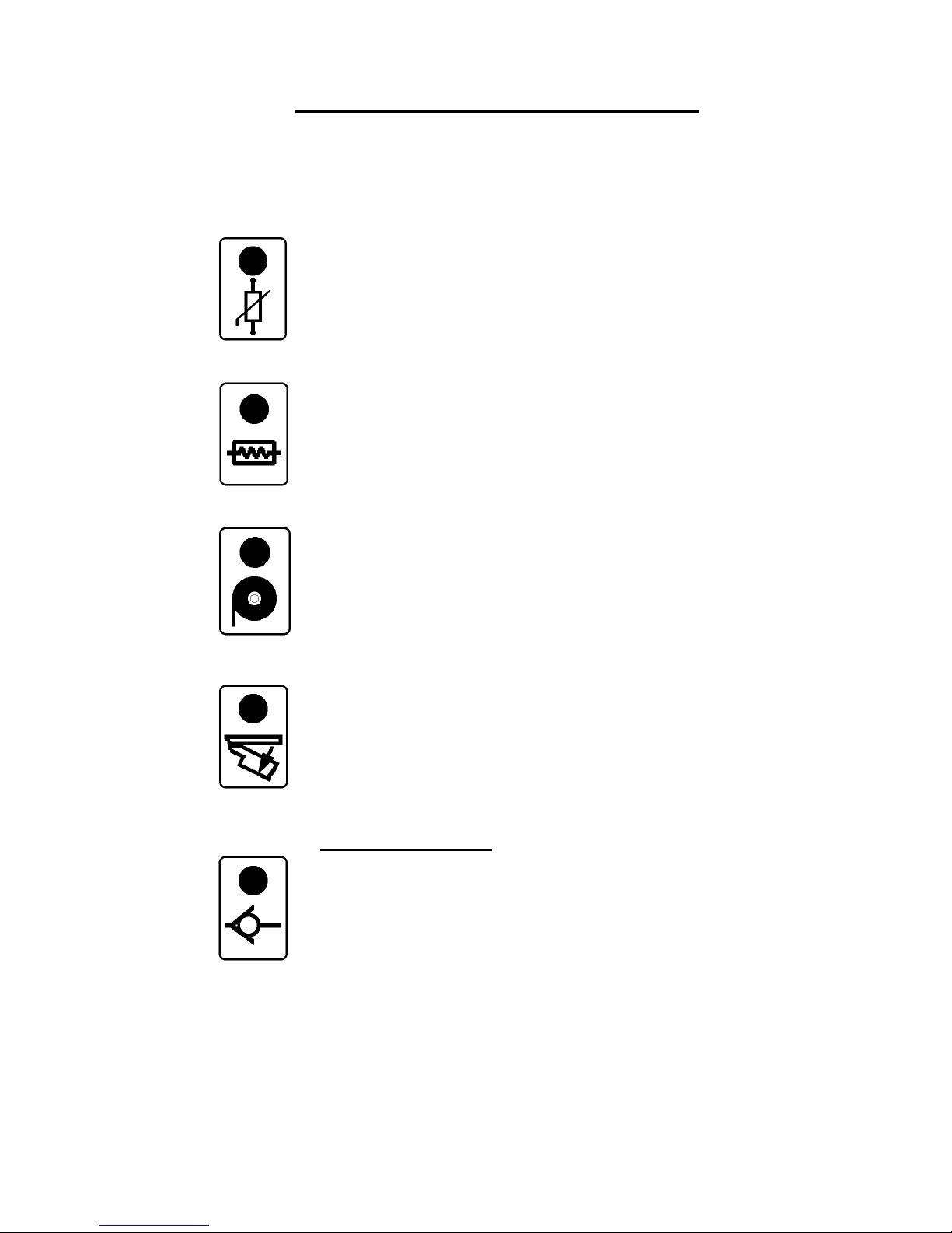
Digi-3-Coder System LED Faults
“Any fault will disable the print switch and activate the fault relay”
Thermistor LED on
Thermistor open circuit.
The heater is switched off and the internal alarm is sounding.
Heater LED on
Heater is open circuit and the internal alarm is sounding.
Foil Run Out LED on
At end of foil roll, the LED is on, and the internal alarm is sounding.
Type Holder Door Opened, LED “O n”
Type holder door is open, the LED is on and the internal alarm is sounding.
Print Button & Test Print Button trigger signals, are disabled.
Low Air Pressure Switch (If connected)
When air pressure is low, the LED is on, and the internal bleeper is sounding.
External Pressure switch required. (Not supplied as standard)
See separate wiring detail.
Digi-3-Coder (Issue 1.2) 6 October 2005 Page 17
Page 18

Drive Roller
Brake Arm Roller
Ink (pigment) Outside
Pinch Drive Roller
Take Off Mandrel
Rewind Mandrell
Cassette Roller
Cassette Roller
Digi-3-Coder Threading Diagram
Digi-3-Coder (Issue 1.2) 6 October 2005 Page 18
Page 19
Digi-3-Coder Mechanical Fault Finding
FAULT
POSSIBLE CAUSE
Insufficient foil pull. Defective stepper motor.
Drive belt is broken.
Drive pulley loose on stepper motor.
Driven pulley loose on bearing housing.
Pinch roller not engaged.
Drive roller damaged or dirty.
Wrong index amount in settings.
Solenoid operates but printer does not. No or low air pressure.
Air pipe damaged.
Dwell time may need to be increased.
Dirty air supply, contaminating pipes etc.
Printer operates but does not print, i.e.
impression but no print.
Printing foil exhausted.
Printing foil not being driven through.
Printing foil not suitable for substrate.
Little or no heat.
Little or not enough dwell time.
Printing foil tracks over to one side. Bent spindle on foil magazine.
Brake arm loose.
Pinch roller misaligned with drive roller.
Type not fitted centrally on type holder.
Foil rewind is loose. Green drive belt worn out or dirty.
Green drive belt is not fitted correctly.
Loose cardboard core on rewind mandrel.
Printer is sluggish. Insufficient air pressure.
Flow restrictors wound in too far.
Faulty valve.
Dirty air supply, contaminating pipes etc.
Digi-3-Coder (Issue 1.2) 6 October 2005 Page 19
Page 20

Digi-3-Coder Operator Instructions
MAGAZINE REMOVAL (See pages 7 & 18)
To remove the foil magazine, slide the catch away from the type holder access door,
hold in place and withdraw the magazine using the two handles.
FOIL THREADING (See page 18)
1. Fit an empty foil core onto the rewind mandrel.
2. Disengage the pinch drive roller.
3. Remove label from a new roll of foil.
4. Fit new roll of foil onto take-off mandrel (note unwind direction as shown on
threading diagram).
5. Thread foil around all rollers as shown on threading diagram. Note, the gloss
side of the foil should face inwards throughout the foil path.
6. Attach end of foil to empty core on rewind mandrel, gloss side facing inwards.
7. Wind foil on a few turn to track and tension it.
8. Engage pinch drive roller.
RE-FITTING FOIL MAGAZINE
Hold the magazine by the two handles, slide onto the locating pins and push to lock in
place. Press the PRINT switch on.
FITTING TYPE/DIE HOLDER
“Never assume that a Type/die holder is cold”
Only pick up a type/die holder by its handle. Ensure that the face of the magnetic catch
is clean. Open the red type holder access door (the alarm will sound continuously),
align the type/die holder within the two side locators and slide in until the magnet
catches on the end plate. Close the door. (Alarm stops sounding)
FOIL FEED ADJUSTMENT (See pages 15 & 16)
This is used to adjust the amount of foil used per print, adjusting the print index button
to achieve the correct index required. A gap of 1 or 2mm is recommended between
each section of used foil.
Digi-3-Coder (Issue 1.2) 6 October 2005 Page 20
Page 21
Digi-3-Coder Print Quality Deterioration
“Print quality deterioration can be attributed to any of the following causes”
POSSIBLE CAUSE CURE
Insufficient foil pull See pages 16 & 19
(Foil Feed Adjustment)
Insufficient air pressure. Check pressure regulator setting.
See that pipes are not damaged.
Printer not level with print base.
Adjust levelling screws.
Too much or too little heat.
Check that settings are correct.
Type holder loose in side locators.
Dirty, worn or damaged dies or type.
Clean or replace.
Damaged or out of position print base
rubber.
Replace or re-position.
Printing foil not compatible with substrate.
Contact foil supplier.
Substrate surface altered, i.e. different
coating.
Contact substrate or foil supplier.
Print ram not completing full stroke.
Open forward flow restrictor (where fitted).
Increase print dwell time.
Substrate moving before print head is clear. Reduce print dwell time.
Print Dwell incorrectly set. Adjust as necessary.
Digi-3-Coder (Issue 1.2) 6 October 2005 Page 21
Page 22

H = Heater Connection (Red Wire)
Stepper Motor
11 = Air Switch volt free 1
(Reed)
Foil Sensor Connections
Door Switch Connections
12 = Air Switch volt free 2
E = Earth (Green/Yellow Wire)
4 = Blue
3 = Black
2 = White
1 = Brown
Connection for Heater & Thermistor
E = Trace/Screen (Green Wire)
13 = Solenoid Valve (+ 24 Volt)
Earth Connections via 19 Pin Plug
Mains Connections via 19 Pin Plug
14 = Solenoid Valve (0 Volt)
1 = Voltage Free (Print Signal 1)
2 = Voltage Free (Print Signal 2)
3 = Isolated Trigger 1 (10-30 volts)
4 = Isolated Trigger 2 (10-30 Volts)
5 = Fault Relay Common
6 = Fault Relay N/O
7 = Fault Relay N/C
8 = Print Relay Common
9 = Print Relay N/O
10 = Print Relay N/C
T = Thermistor Connection (Black Wire)
T = Thermistor Connection (Black Wire)
H = Heater Connection (Red Wire)
PCB 312060
F1 = Fuse Connection (Brown Wire)
Signal Wires via 19 Pin Plug
F2 = Fuse Connection (Brown Wire)
1 = Pink Wire
4 = Green Wire
3 = Black Wire
2 = Blue Wire
3 = Not Used
2 = White
1 = White
N = Neutral 0V (Blue Wire)
L = 110 - 230 AC Volts (Brown Wire)
Digi-3-Coder Main Circuit Board Connections
(see next pages)
Digi-3-Coder (Issue 1.2) 6 October 2005 Page 22
Page 23

Digi-3- Coder (Wiring Connections) Trident 19 Way Plug on Printer
Signal No. Wire type Pin No. Colour Length
Mains Neutral
(Part No. PIN 508218)
20 AWG
0.5mm
2
F BLUE 70mm
Mains Live
(Part No. PIN 508218)
20 AWG
0.5mm
2
G BROWN 80mm
Mains Earth
(Part No. PIN 508218)
20 AWG
0.5mm
2
H
GREEN/YELLOW
70mm
Screen/Trace
(Part No. PIN 508218)
20 AWG
0.5mm
2
J GREEN 70mm
Volt free trigger 1
(Part No. PIN 508219)
24 AWG
1 0.22mm
2
T GREEN 75mm
Volt free trigger 2 (GND)
(Part No. PIN 508219)
24 AWG
2 0.22mm
2
S YELLOW 75mm
Isolated Voltage trigger 1
(Part No. PIN 508219)
24 AWG
3 0.22mm
2
R WHITE 85mm
Isolated Voltage trigger 2
(Part No. PIN 508219)
24 AWG
4 0.22mm
2
E BLACK 85mm
Fault relay Common
(Part No. PIN 508219)
24 AWG
5 0.22mm
2
K ORANGE 90mm
Fault relay NO
(Part No. PIN 508219)
24 AWG
6 0.22mm
2
U BROWN 90mm
Fault relay NC
(Part No. PIN 508219)
24 AWG
7 0.22mm
2
V GREY 100mm
Print relay Common
(Part No. PIN 508219)
24 AWG
8 0.22mm
2
P PINK 100mm
Print relay NO
(Part No. PIN 508219)
24 AWG
9 0.22mm
2
D GREY/ BLUE 110mm
Print relay NC
(Part No. PIN 508219)
24 AWG
10 0.22mm
2
C MAUVE 110mm
Air fail volt free 1
(Part No. PIN 508219)
24 AWG
11 0.22mm
2
L YELLOW/RED 115mm
Air fail volt free 2 (GND)
(Part No. PIN 508219)
24 AWG
12 0.22mm
2
N GREEN/RED 115mm
Solenoid +
(Part No. PIN 508219)
24 AWG
13 0.22mm
2
A RED 125mm
Solenoid - (GND)
(Part No. PIN 508219)
24 AWG
14 0.22mm
2
B BLUE 125mm
Digi-3-Coder (Issue 1.2) 6 October 2005 Page 23
Page 24
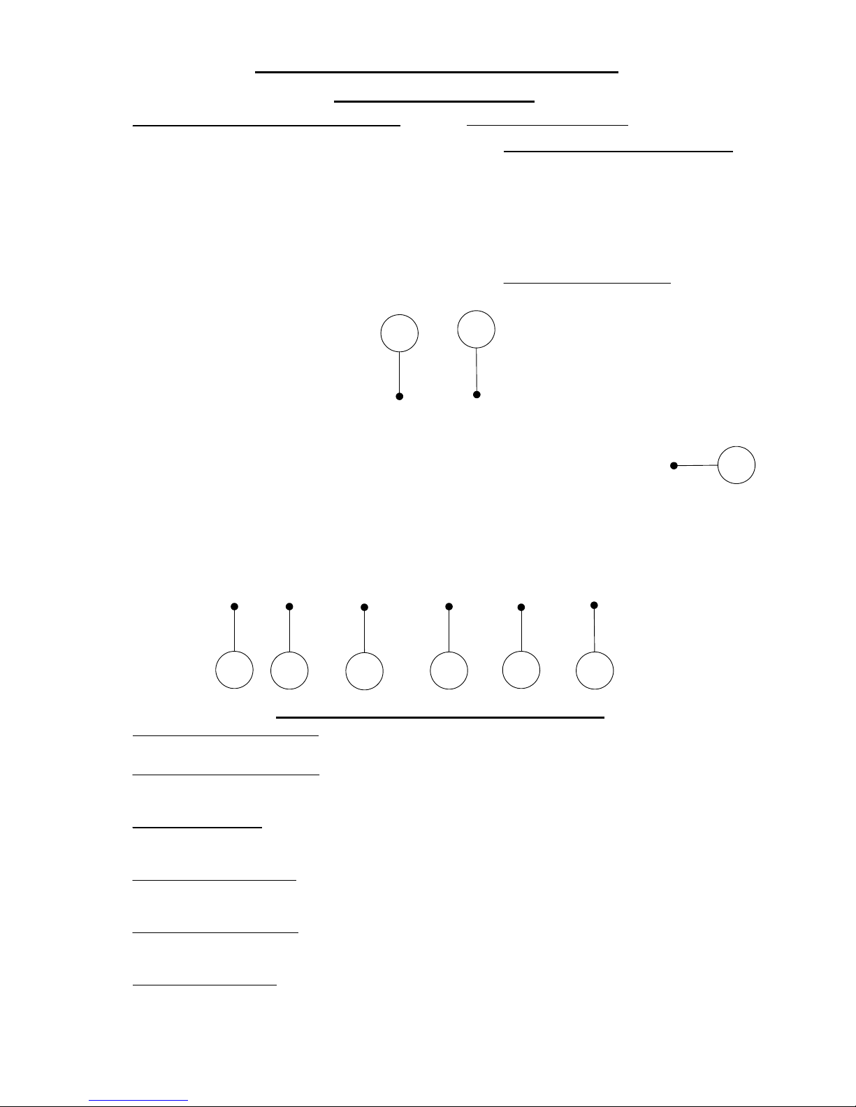
7
8
9
3
1
4
5
6
2
N = Fault Relay N/C
K = Print Relay N/C
H = Isolated Voltage trigger 2
A = Air Fail volt free 1
C = Solenoid Valve + 24 Volt DC
E = Volt free trigger 1
L = 110-230 AC Voltage Input
G = Isolated Voltage trigger 1
F = Volt free trigger 2
L = Live Mains Connection (110 - 230 Volts AC) Autosensed
J = Print Relay N/O
I = Print Relay Common
OEM and Customer Connections
M = Fault Relay N/O
L = Fault Relay Common
Digi-3-Coder OEM Connections PCB
N = Neutral 0 Volt
E = Earth Connection
1 + 2 = Connections to Printer 19 way Socket.
D = Solenoid Valve 0 Volt
B = Air Fail volt free 2
4 = Low Air Switch connections.
If Air Switch not fitted, please link "A" + "B". (Voltage Free)
5 = Solenoid Valve Connections
(24 Volt DC, 80mA current nominal)
Red Wire to "+"
Blue Wire to "-"
6 = Print Signal Inputs
Connect any Voltage Free contacts to both "FREE" terminals. (Microswitch, relay or PLC contacts etc.)
Connect any Voltage Pulse (10 - 30 Volts AC or DC) Polarity unimportant.
7 = Print Relay Connections
(Controlled by the Print Switch)
Connections: Common (COM), Normally Open (N/O) or Normally Closed (N/C)
Rated at 24V DC, 1 amp.
8 = Fault Relay Connections
(Any Fault raises the Alarm & changes over the relay)
Connections: Common (COM), Normally Open (N/O) or Normally Closed (N/C)
Rated at 24V DC, 1 amp.
9 = Supply Voltage Input
E = Earth connection
N = Neutral Connection (O Volt)
Printer Connections
3 = Mains Link Connections
If fitted into Connection Box Assembly:-
(Part No. BOX 312085)
Connect both "L" terminals to each side
of mains switch. (inividual switch contact)
Connect both "N" terminals to the other
sides of switch. (individual switch contact)
If used in a parent machine:-
Connect both "L" terminals together.
Connect both "N" terminals together.
Digi-3-Coder (Issue 1.2) 6 October 2005 Page 24
Page 25

Digi-3- Coder (Wiring Connections) Trident 19 Way Socket on Connection Cable
“Cable lengths supplied of 1.5 metres or 2.9 metres, stripped at the socket end 45mm”
Signal Name & Socket Connector Wire Plug No Colour Length
Mains Neutral
(Part No. SKT 508325)
20 AWG
N 0.5mm
2
F BLUE 45mm
Mains Live
(Part No. SKT 508325)
20 AWG
L 0.5mm
2
G BROWN 45mm
Mains Earth
(Part No. SKT 508325)
20 AWG
E 0.5mm
2
H
GREEN/YELLOW
45mm
Screen/Trace
(Part No. SKT 508325)
20 AWG
CUT OFF 0.5mm
2
J GREEN 45mm
Volt free trigger 1
(Part No. SKT 508326)
24 AWG
E 0.14mm
2
T GREEN 45mm
Volt free trigger 2 (GND)
(Part No. SKT 508326)
24 AWG
F 0.14mm
2
S YELLOW 45mm
Isolated Voltage trigger 1
(Part No. SKT 508326)
24 AWG
G 0.14mm
2
R WHITE 45mm
Isolated Voltage trigger 2
(Part No. SKT 508326)
24 AWG
H 0.14mm
2
E BLACK 45mm
Fault relay Common
(Part No. SKT 508326)
24 AWG
L 0.14mm
2
K ORANGE 45mm
Fault relay NO
(Part No. SKT 508326)
24 AWG
M 0.14mm
2
U BROWN 45mm
Fault relay NC
(Part No. SKT 508326)
24 AWG
N 0.14mm
2
V GREY 45mm
Print relay Common
(Part No. SKT 508326)
24 AWG
I 0.14mm
2
P PINK 45mm
Print relay NO
(Part No. SKT 508326)
24 AWG
J 0.14mm
2
D LIGHT BLUE 45mm
Print relay NC
(Part No. SKT 508326)
24 AWG
K 0.14mm
2
C MAUVE 45mm
Air fail volt free 1
(Part No. SKT 508326)
24 AWG
A 0.14mm
2
L YELLOW/BLACK 45mm
Air fail volt free 2 (GND)
(Part No. SKT 508326)
24 AWG
B 0.14mm
2
N GREEN/BLACK 45mm
Solenoid +
(Part No. SKT 508326)
24 AWG
C 0.14mm
2
A RED 45mm
Solenoid - (GND)
(Part No. SKT 508326)
24 AWG
D 0.14mm
2
B BLUE 45mm
Digi-3-Coder (Issue 1.2) 6 October 2005 Page 25
Page 26

Dip Switch Location
(enlarged view)
Digi-3-Coder Dip Switch Settings & Explanations
The dip switches are located behind the membrane, inside the printer.
Access by removing the side guard of the printer.
Default Dip Switch Settings
Europe
USA
1 = OFF 1 = ON
2 = OFF 2 = OFF
3 = OFF 3 = OFF
4 = ON 4 = ON
Description of Switches
1 = CENT/FAHR
Off = Centigrade,
ON = Fahrenheit
2 = THERMISTOR 1/2
Off = USP Thermistor (Standard)
ON = Alternative Thermistor
3 = FOIL ON/OFF
Off = Foil Sensor Fitted.
ON = Not Fitted
4 = TEMP STOP YES/NO
Off = Prints only within temperature range
ON = Prints at any temperatures.
Digi-3-Coder (Issue 1.2) 6 October 2005 Page 26
Page 27
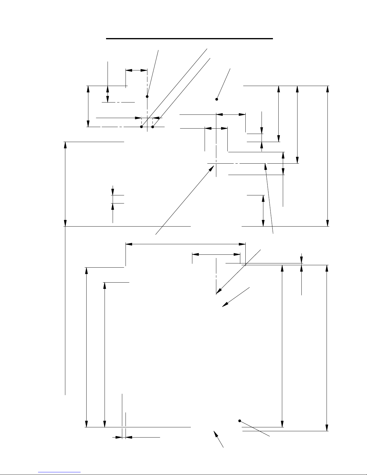
97
36.50
21.5
51.50
27
14 crs
Digi-3-Coder Dimensional Drawing
150
Centre Line Print
207
60
203
Typeholder Door
181.5
Substrate Reference
2.50
200
4.5
Cassette
Latch
19 Way Connection Plug
6mm Red Pipe (Air Connection)
39
176
Clearance for Magazine Removal, 210mm
Part No. FUS 503512
28.50
70
10
28.50
10
Centre Line Print
M10 THREAD
Fuseholder (2 amp Antisurge)
6mm Black Pipe (Air Connection)
Digi-3-Coder (Issue 1.2) 6 October 2005 Page 27
Page 28
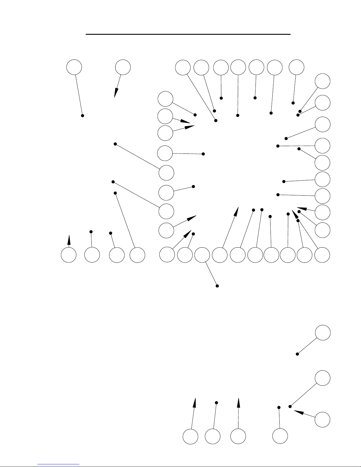
18
19
20
33
37
38
38
15
10
11431
6
17
44
32
39
44
29
33
21
112630
43
8
8
33
17
20
28
8
34
25
31
2
40
16
9
Digi-3-Coder Cassette Spare Parts Drawing
(Part No. CAS 311000)
35
27
5
4
3
12
12
13
For item No's referencing see next page.
Digi-3-Coder (Issue 1.2) 6 October 2005 Page 28
Page 29

Digi-3-Coder Cassette Spare Parts Listing
ITEM PART NUMBER DESCRIPTION QTY.
1 PLA 311025 Plate Cassette 1
2 M3SCS10 M3 Cap Screw x 10 Long 2
3 BUS 620035 Bush 1
4 HAN 530502 Handle 1
5 SRI 620013 Spindle 1
6
ROL 620231 Pinch Roller & Yoke Assembly 1
7 M5SSS08
M5 Socket Set Screw x 8 Long
1
8 M5CSS16
M5 Countersunk Screw x 16 Long
4
9
M4CSS20
M4 Countersunk Screw x 20 Long
2
10 DRI 620204 Drive Roller Assembly 1
11
BLO 311028 Block Band Brake Adjuster 1
12 HAN 311023 Handle Cassette 2
13 THU 620127 Thumb Plate 1
14 LOC 620129 Locking PLATE 1
15 SUP 190024 Support 2
16
GUI 311032 Foil Guide 1
17 M4SSS16 M4 Socket Set Screw 16 Long 11
18
SPI 311014 Spindle Roller 6
19 ROL 620018 Roller 6
20 WAS 120035 Washer 8
21 DAN 311035 Dancing Arm Assembly 1
22
WAS 311015
Washer Top 1
23
M4CSS16 M4 Counter Sunk Screw 16 Long 1
24 WAS 311016 Washer Middle 1
25 M3WAS M3 Stainless Steel Washer 1
26 M3SCS06 M3 Cap Screw x 6 Long 1
27 PLA 311029 Digi-3-Coder Identification Plate 1
28
M4BHS08 M4 Button Head Screw 08 Long 6
29 M3SCS16 M3 Socket Cap Screw 16 Long 2
30 SPR 190017 Spring Post 1
31 M4SCS16
M4 Countersunk Screw x 16 Long
3
32 DRI 110022 Eurocode Drive Belt 1
33 SOC 311036 Cassette Location Socket Assembly 2
34 M4CSS08
M4 Counter Sunk Screw x 8 Long (Steel)
1
35 DOO 311037 Door Assembly 1
36
M4CSS10 M4 Counter Sunk Screw 10 Long 1
37 SPI 311011 Spindle Drive Roller 1
38
SPI 311012 Spindle 2
39 HUB 620201 Take Off Hub Assembly 1
40 HUB 620202-1 Rewind Hub Assembly 1
41
SLE 311024
Sleeve Nip Roller Stop 1
42 M4SCS20
M4 Socket Cap Screw x 20 Long
1
43
LAB 506506 Eurocode Threading Diagram 1
44 M4SCS8 M4 Cap Screw x 8 Long 2
Digi-3-Coder (Issue 1.2) 6 October 2005 Page 29
Page 30

42
47
33
31
36
38
14
37
43
29
44
Digi-3-Coder Printer Body Spare Parts Drawing
24
9
39
4
6
46
41
7
13
1
44
2
30
22
32
31
40
8
47
Digi-3-Coder (Issue 1.2) 6 October 2005 Page 30
Page 31
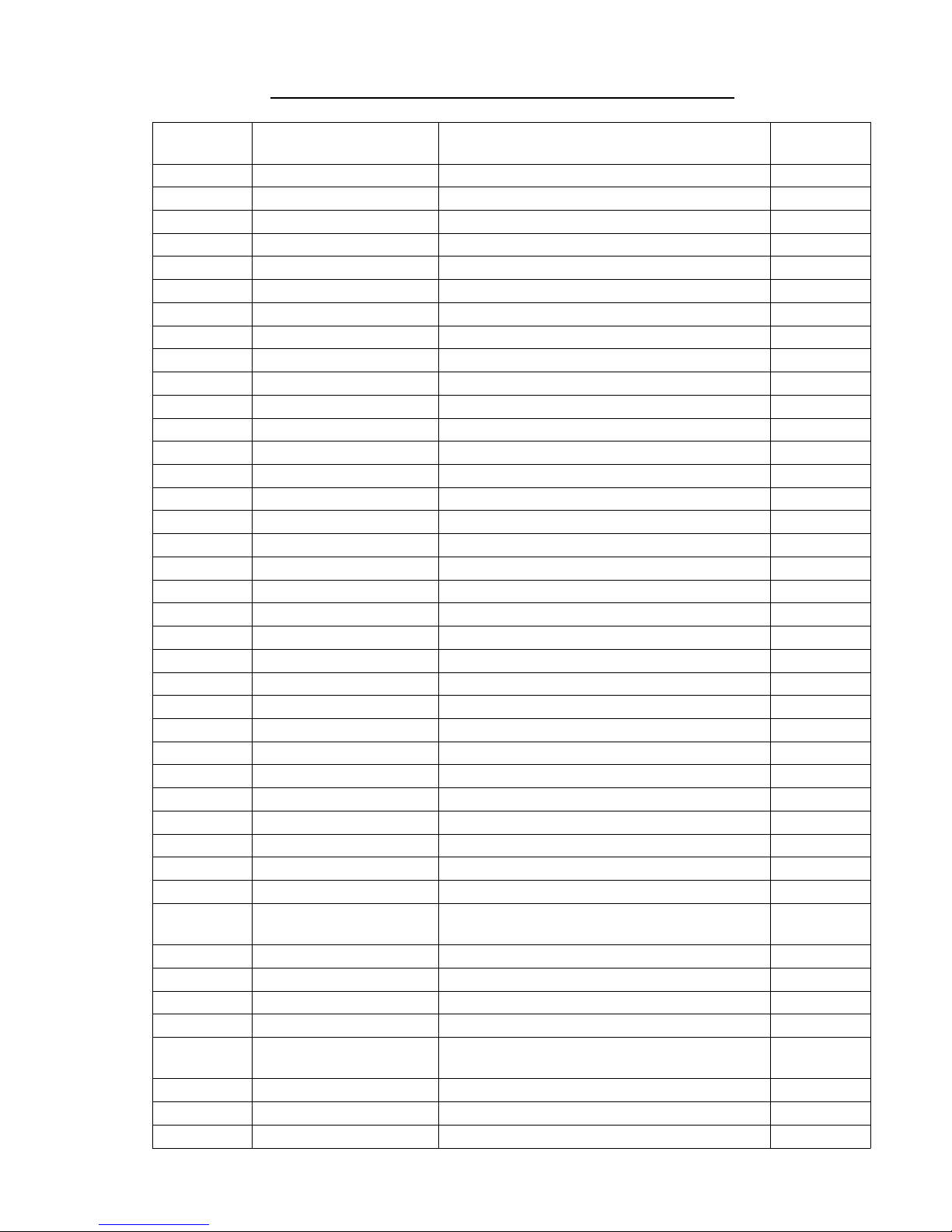
Digi-3-Coder Printer Spare Parts Listing
ITEM PART NUMBER DESCRIPTION QTY.
1
PLA 312030
Plate Digi-3-Coder Body 1
2 BLO 312018 Rear Guard Block 1
3
SPA 312023
Plate Spacer 5
4
M4CSS40
M4 Countersunk Screw 40 Long 5
5 SPA 312024 P C B Short Spacer 5
6
SEN 312086
Assembly Foil Sensor 1
7
M4SCS16
M4 Socket Cap Screw x 16 Long
1
8 SPA 312022 Cassette Location Spacer 2
9
CYL 312068
Cylinder Assembly 1
10
TUB 312073
Red Air Tube 1
11
TUB 312074
Black Air Tube 6 1
12
PUL 312036
48 Teeth Pulley 1
13 M3SCS12 M3 Cap Screw x 12 long 3
14
M6SCS60
M6 Socket Cap Screw x 60 Long
2
15
M4WAS
M4 Stainless Steel Washer 8
19 M6SCS20 M6 Socket Cap Screw 20 Long 2
20
GRO 312047
4mm Hole Grommet 1
21
M3SCS25
M3 Socket Cap Screw x 25 Long
1
22 BLO 312019 Front Block 1
24
LOC 312012
Taperered Location Rod 2
25
PLA 312081
Plate Guard Air 1
26 GUA 312053 Guard Protection 1
27
M4NUT
M4 Full Nut 2
28
PCB 312060
Main Assembly PCB 1
29 M4CSS12 M4 Counter Sunk Screw 12 Long 1
30
ASY 312091
Side Guard Assembly 1
31
M3SCS06
M3 Cap Screw x 6 Long 8
32
PLA 312038 Plate Cylinder 1
33
PLU 313012
Plug 19 Way (Trident) 1
36
MOT 312087
Assembly Ribbon Motor 1
37 BEA 312089 Bearing Block Assembly 1
38
PLA 312094
Plate Coder Support Assembly 1
39
PLA 312095
Plate Cylinder Location Assembly 1
40
REE 312107
Reed Switch Assembly 1
41 SPA 312082 Sensor Spacer 1
42
BLO 312106
Block Air Connection Assembly 1
43
WAS 312039
Washer Cassette Stop 1
44
SCR 312110
M5 Shoulder Screw 4
45
M5SCS16
M5 Cap Screw x 16 Long 2
46 M4SCS08 M4 Cap Screw x 8 Long 6
47
FUS 503506
Fuseholder 1
Digi-3-Coder (Issue 1.2) 6 October 2005 Page 31
Page 32

4
5
6
714
8
10
16
11
17
18
153
1213
1
9
12
2
13
Digi-3-Coder Connection Box
(Detail Drawing)
Digi-3-Coder (Issue 1.2) 6 October 2005 Page 32
Page 33
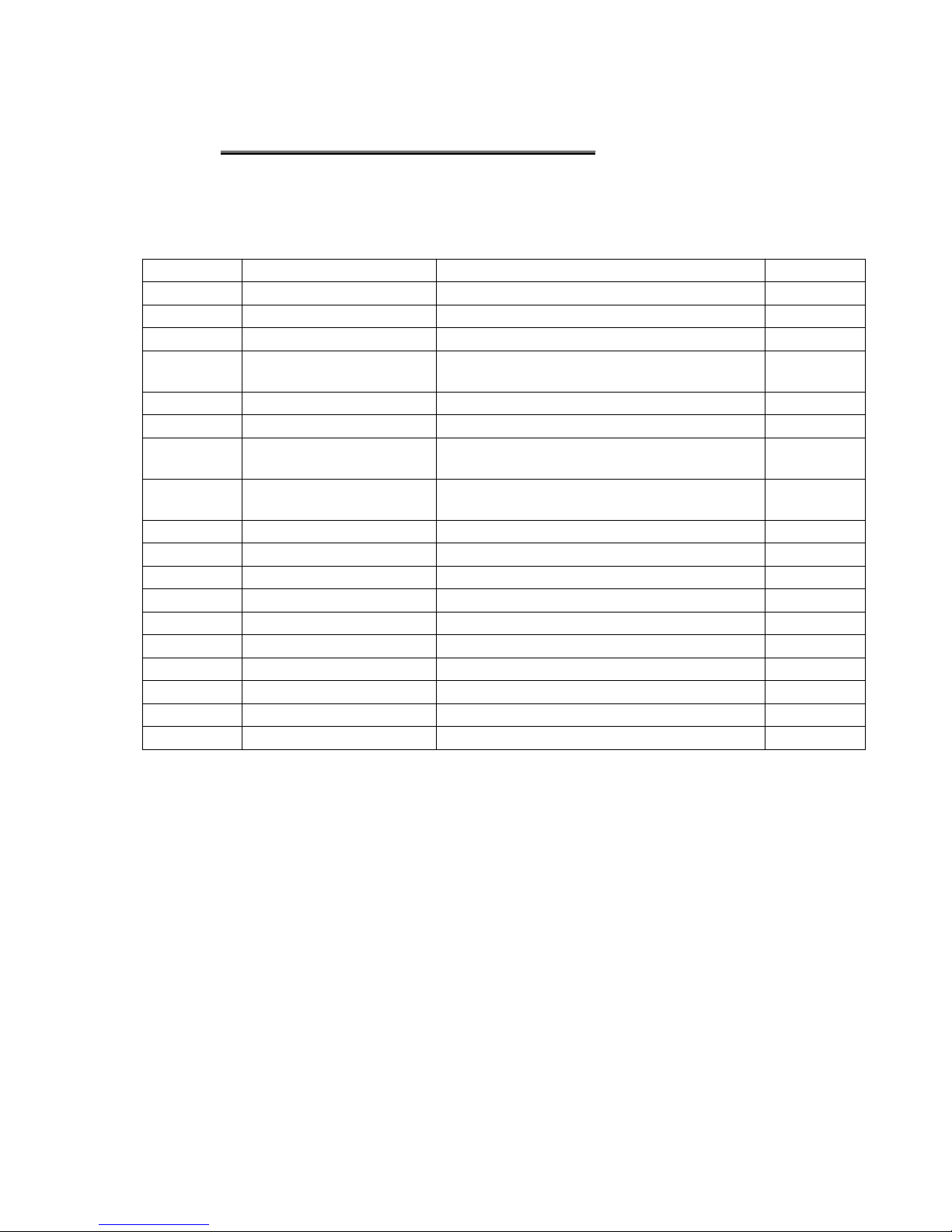
Digi-3-Coder Connection Box
(Parts Listing)
(Part No. BOX 312085)
ITEM
PART NUMBER
DESCRIPTION QTY.
1
BOX 312033 Machined Connection Box 1
2
PLA 312083
Gland Plate 1
3
ELE 312042 Switch Rocker 1
4
GLA 313004
Cable Gland Skintop M16 1
5
GLA 312041 Cable Gland 5
6
NUT 312040 Lock Nut 5
7
M3SCS08
M3 Socket Cap Screw x 08 Long 4
8
M4CSS30
M4 Counter Sunk Screw 25 Long 2
9
VAL 312034 Solenoid Valve 1
10
VAL 312035
Flow Control Valve 2
11
M3WAS
M3 Stainless Steel Washer 4
12
M4WAS M4 Stainless Steel Washer 4
13
M4NUT
M4 Full Nut 4
14
M3NUT
M3 Full Nut 4
15
PCB 313006 OEM Connections Assembly 1
16
WAS 311015
Washer Top 2
17
M3STS06 M3 Self Tapping Screw x 06 Long 4
18
M3STS10
M3 Self Tapping Screw x 10 Long 4
Digi-3-Coder (Issue 1.2) 6 October 2005 Page 33
Page 34
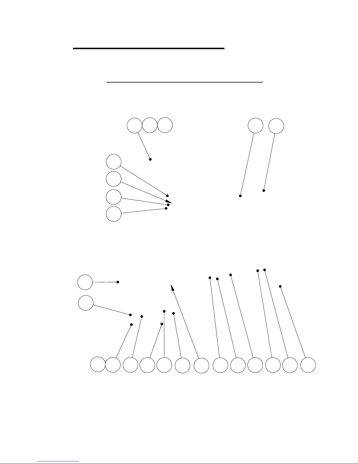
11
13
27
8
22
15
5
1
18
4
6
26
25
6
21
2414
22
13
9
17
16
24
(Detail Drawing)Digi-3-Coder Cylinder Assembly
7
Heater & Thermistor removed for clarity.
See page 36 for Heater & Thermistor Part Numbers.
Digi-3-Coder (Issue 1.2) 6 October 2005 Page 34
Page 35
Digi-3-Coder Cylinder Assembly
(Parts Listing)
ITEM PART NUMBER DESCRIPTION QTY.
1
CYL 312066
Air Cylinder 1
2
PAC 190028
Packing Block 1
3
INS 120012
Insulating Plate 1
4 HEA 120013 Heater Block 1
5
KEE 120030
Keep Plate 1
6
SID 120014
Side Locator Plate 2
7
M3CSS08
M3 Contersunk Screw x 8 Long 2
8
M4SCS40
M4 Cap Screw x 40 Long 4
9
ANG 312057
Angle Terminal Support 1
10 BLO 312058 Block Insulator 1
11
WASM3SHK
Shakeproof Washer M3 6
12
M3SCS25
M3 Cap Screw x 25 Long
2
13
M3SCS16
M3 Socket Cap Screw 16 Long 2
14 ELE 312011 Terminal Block 1
15
M2.5SCS12
M2.5 Cap Screw x 12 Long
4
16
SLE 312075
Spring Sleeve 2
17 SPR530009
Tension Spring
2
18 TEE 312037 Cylinder Tee Nut 2
20
GRO 312031
Plastic Grommet 5
21
M4SSS08
M4 Socket Set Screw 8 Long 2
22 M3NUT M3 Full Nut 2
23 M2.5NUT M2.5 Full Nut 2
24
ELB 312067
Swivel Elbow 6.0mm 2
25
M4WASSHK
M4 Shakeproof Washer
5
26 M4SCS8 M4 Cap Screw x 8 Long 4
27
M4SSS06
M4 Socket Set Screw 06 Long 2
Digi-3-Coder (Issue 1.2) 6 October 2005 Page 35
Page 36

Digi-3-Coder Essential Spares List
Description Part No.
1. Cassette Brake Tension Spring (2 off) SPR 530008
2. Timing Belt (Digi-3-Coder) BEL 762064
3. Drive Roller Assembly DRI 620204
4. Cassette Take Up Belt (2 off) DRI 110022
5. Cassette Brake Strap BRA 311031
6. Grey Self Adhesive Print Base SABASE
300 x 450mm sheet
or
7. White Silicone Rubber Print Base SRBASE
300 x 300 x 3mm thick sheet
8. Cartridge Heater (240v x 500watt) HEA 312070
9. Thermistor Probe (Digi-3-Coder) THE 312080
10. Reed Switch (Door Sensor) REE 312107
11. Low Foil Sensor Assembly SEN 312086
12. Pack of Mains Fuses (5) 2Amp Anti-Surge FUS 393502
Digi-3-Coder Comprehensive Spares List
Description
Part No,
1. Cassette Brake Tension Spring (2 off) SPR 530008
2. Timing Belt (Digi-3-Coder) BEL 762064
3. Drive Roller Assembly DRI 620204
4. Cassette Take Up Belt (2 off) DRI 110022
5. Cassette Brake Strap BRA 311031
6. Grey Self Adhesive Print Base SABASE
300 x 450mm sheet
or
7. White Silicone Rubber Print Base SRBASE
300 x 300 x 3mm thick sheet
8. Cartridge Heater (240v x 500watt) HEA 312070
9. Thermistor Probe (Digi-3-Coder) THE 312080
10. Reed Switch (Door Sensor) REE 312107
11. Low Foil Sensor Assembly SEN 312086
12. Pack of Mains Fuses (5) 2Amp Anti-Surge FUS 393502
13 Main Circuit Board (Digi-3-Coder) PCB 312060
14. Membrane Assembly (Including PCB) KEY 312090
15. Solenoid Valve without fittings VAL 312034
16. Ribbon Motor Assembly MOT 312087
17. Cable Socket 1.5 Metre Long (Connecting Box) CAB 313019
Digi-3-Coder (Issue 1.2) 6 October 2005 Page 36
Page 37
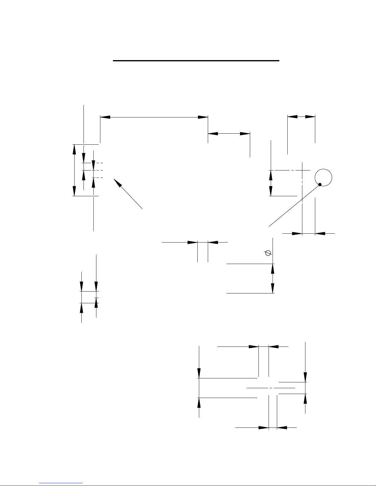
15.75
8
4.62 CRS
4.62 CRS
7
3.80
6.35
18
1.75
1.30
1.50
3
"T" SLOT DETAILS
Digi-3-Coder Standard Typehoder
3 Rows T'Slot type
Please note that the standard Eurocode Typehoder does not fit the Digi-3-Coder
17
See Below for T Slot Details
"T
25.65
31.50
65.85
3 "T" Slots, Maximum 3 Lines
Digi-3-Coder (Issue 1.2) 6 October 2005 Page 37
Page 38

cap screw provided. This raises the sensor position by 2mm.
the mounting plate. Then refix the assembly to the printer body, using the M4
When using 38mm width foil, you must position the 2mm spacer underneath
If other widths of foil are to be used in the Digi-3-Coder, you must contact
your local supplier for additional spacers and screws.
Digi-3-Coder Foil Sensor Instructions
2mm Spacer (Part No. SPA 312082)
The mounting plate fits into the pocket of the main plate. (Standard Printer)
.
M4 Cap Screw x 16 long
(Part No. SEN 312086)
Standard 40mm width foil, fit the 2mm spacer above the mounting plate
Foil Sensor Assembly
Mounting Plate
Digi-3-Coder (Issue 1.2) 6 October 2005 Page 38
Page 39

Digi-3-Coder Calibration Method
NOTE
The standard Digi-3-Coder is calibrated at 130ºC or 266°F
Unless you are changing the temperature to the extremes, the default calibration should be
left alone.
Calibration & Temperature Range:= 70ºC to 220ºC (158ºF to 428ºF)
External Calibration Method
1. Switch the Digi-3-Coder unit on and adjust the temperature setting to 130ºc or 266ºF.
2. Leave on for 10 to 15 minutes, allowing the temperature to stabilise.
3. Measure the temperature at the type face using a temperature probe.
4. Allow the temperature probe to stabilise before noting the reading.
5. Adjust the Digi-3-Coder set point to match the temperature probe reading.
6. Press both the up and down arrow keys at the same time, then press the print switch.
7. The controller is now calibrated.
Note.
Calibration may have to be repeated, for accuracy of temperatures.
“For operating temperatures above 180ºc or 356ºF calibrate at 200ºC or 392ºF”
Digi-3-Coder (Issue 1.2) 6 October 2005 Page 39
Page 40

Digi-3-Coder Airbourne Noise Emissions
Comprehensive tests have been carried out with the Digi-3-Coder fitted in a standard printer
frame and mounted onto a typical label applicator. Measurements were taken at 1.6 metres
above floor level and 1 metre away from the printer in all directions.
The measuring equipment used for conducting the tests was a Digital Sound Level Meter,
Type d-1405E supplied by Lucas CEL. Before the tests were carried out, the instrument was
calibrated and fitted with a foam windshield.
The results shown are based upon a standard type application for the printer, the operating air
pressure was set at 6 bar and the flow restrictors correctly adjusted.
The noise levels shown below are the equivalent continuous “A-weighted” sound pressure
levels in decibels “dB(A)”.
Prints Per Minute Noise Levels – Decibels (dB)
100 65
200 69
300 72
400 75
Digi-3-Coder (Issue 1.2) 6 October 2005 Page 40
Page 41

Digi-3-Coder Machine Serial Number Identification
2005
0010-05
110 - 230 AC
ONE
Digi-3-Coder
2 AMP
The identification label can be found on the side guard of the printer
Always quote the model and serial number when ordering spare parts.
Year of Manufacture
Serial Number
50 or 60
2 AMP MAX
Model of Printer
Fuse Rating
Company Logo
Manufacturer Name & Address
CE Mark
Digi-3-Coder (Issue 1.2) 6 October 2005 Page 41
Page 42

STANDARD WARRANTY TERMS AND CONDITIONS – HOT FOIL PRINTERS
All Open Date Hot Foil Printers Carry a twelve (12) month return to base (at our
discretion) warranty.
Open Date printers should be installed and operated according to the instructions
given in the operating manual. No liability will be accepted for faults caused by
incorrect installation or operation of the equipment or if the product has been altered
or subjected to unreasonable use.
The following components are not covered by the warranty as they will be subject to
wear and tear: -
1. Print base rubber.
2. Hardened steel type.
Should you have cause to claim for repair under warranty then please contact our
service department stating the model, serial number of the product and the nature of
the problems or faults.
We reserve the right to charge for components replaced during the warranty period,
which are subsequently found to be damaged due to any of the above conditions not
being followed.
Any items repaired or replaced under warranty will carry the balance of the original
warranty period only.
Digi-3-Coder (Issue 1.2) 6 October 2005 Page 42
Page 43

OPEN DATE GROUP COMPANIES
FRANCE
OPEN DATE FRANCE
Z.I. D’Attichy
No.8, Voie Industrielle
60350 Attichy.
Local Tel:- 03 44 42 94 43
Local Fax:- 03 44 42 17 17
International Tel:- 0033 3 44.42.94.43
International Fax:- 0033 3 44.42.17.17
GERMANY
OPEN DATE GmbH
Mittlerer Stämmig 4
D - 97292 Üttingen
Local Tel:- 09369 9824 0
Local Fax:- 09369 9824 24
International Tel:- 0049 9369 9824 0
International Fax:- 0049 9369 9824 24
U.S.A.
OPEN DATE SYSTEMS INC.
Springfield Road
PO Box 538
Georges Mills
NH 03751-0538.
Local Tel:- 603 763 3444
Local Fax:- 603 763 4222
International Tel:- 001 603 763 3444
International Fax:- 001 603 763 4222
INTERNATIONAL AGENTS & DISTRIBUTORS
Please visit:
www.opendate.co.uk
for a list of international agents & distributors.
Digi-3-Coder (Issue 1.2) 6 October 2005 Page 43
 Loading...