

iiCCoonnnneecctt662255WW UUsseerr GGuuiiddee
44--PPoorrtt AADDSSLL,, AADDSSLL 22//22++
Copyright
Copyright© 2006 OPEN Networks Pty Ltd. All rights reserved. The content of this manual is subject to change without notice. The
information and messages contained herein are proprietary to OPEN Networks Pty Ltd. No part of this manual may be translated,
transcribed, reproduced, in any form, or by any means without prior written permission by OPEN Networks Pty Ltd.
Disclaimer
For content and procedures available in this document, OPEN Networks Pty Ltd does not warrant or assume any legal liability or
responsibility for the accuracy, completeness, or usefulness of any information, apparatus, product, or process disclosed.
Revision: v1.2
Date Released: February, 2007
WWiirreelleessss RRoouutteerr
February 2007

iConnect 625W ADSL Router User Guide
Table of Contents
1. Introduction..............................................................................................................5
1.1 Features............................................................................................................6
2. iConnect625W Overview.........................................................................................7
2.1 Important Safety Instructions............................................................................7
2.2 System Requirements.......................................................................................8
2.3 Package Contents ............................................................................................8
2.4 Appearance ......................................................................................................9
2.4.1 The Front LEDs................................................................................................................ 9
2.4.2 The Rear Ports............................................................................................................... 10
3. Setting Up Your iConnect625W Router................................................................11
3.1 Default Settings ..............................................................................................12
3.2 Factory Default Settings..................................................................................13
3.3 Logging Into Your iConnect625W...................................................................14
4. PC Network Connection........................................................................................ 15
4.1 Configuring Network Computers Using Windows XP .....................................15
4.2 Configuring Computers in Windows 2000.......................................................17
4.3 Configuring Computers In Windows 98/ME....................................................19
4.4 Configuring Computers In Windows Vista.......................................................21
5. Understanding The Web Interface........................................................................24
5.1 Web Interface Components............................................................................24
5.1.1 Buttons........................................................................................................................... 24
5.1.2 Menus ............................................................................................................................ 24
6. Home.......................................................................................................................25
7. Setup.......................................................................................................................26
7.1 LAN Setup ......................................................................................................27
7.1.1 LAN Configuration.......................................................................................................... 27
7.2 Setting Up a WAN Connection........................................................................32
7.2.1 PPPoE Connection Setup..............................................................................................33
7.2.2 PPPoA Connection Setup..............................................................................................43
7.2.3 Static Connection Setup ................................................................................................ 48
7.2.4 DHCP Connection Setup...............................................................................................51
7.2.5 Bridged Connection Setup............................................................................................. 54
7.2.6 CLIP Connection Setup ................................................................................................. 57
7.2.7 Modify an Existing Connection.......................................................................................60
7.2.8 Delete an Existing Connection.......................................................................................61
7.2.9 Modem Setup................................................................................................................. 62
8. Advanced................................................................................................................64
8.1 UPnP ..............................................................................................................66
8.2 SNTP..............................................................................................................68
8.3 SNMP .............................................................................................................71
8.4 Port Forwarding..............................................................................................74
8.4.1 Allow Incoming Ping....................................................................................................... 79
8.4.2 DMZ ............................................................................................................................... 79
ii

8.4.3 Custom Port Forwarding................................................................................................ 82
iConnect 625W ADSL Router User Guide
8.5 IP Filters..........................................................................................................84
8.6 LAN Clients.....................................................................................................88
8.7 LAN Isolation ..................................................................................................91
8.8 Remote Web Access ......................................................................................92
8.9 Bridge Filters...................................................................................................94
8.9.1 Editing Bridge Filters...................................................................................................... 97
8.9.2 Deleting Filter Rules....................................................................................................... 98
8.10 Dynamic DNS Client....................................................................................99
8.11 IGMP Proxy ...............................................................................................101
8.12 Static Routing ............................................................................................104
8.13 Dynamic Routing .......................................................................................106
8.14 Policy Database.........................................................................................109
8.15 Ingress.......................................................................................................112
8.15.1 Untrusted Mode............................................................................................................113
8.15.2 Ingress Layer 2 ............................................................................................................ 114
8.15.3 Ingress Layer 3 ............................................................................................................ 117
8.15.4 Static Configuration...................................................................................................... 119
8.16 Egress........................................................................................................121
8.16.1 No Egress .................................................................................................................... 121
8.16.2 Egress Layer 3............................................................................................................. 122
8.16.3 Resetting Egress Mode................................................................................................ 123
8.17 Shaper.......................................................................................................124
8.17.1 HTB Queue Discipline.................................................................................................. 124
8.17.2 Low Latency Queue Discipline..................................................................................... 126
8.17.3 PRIOWRR....................................................................................................................128
8.18 SSH Access Control ..................................................................................130
9. Wireless................................................................................................................131
9.1 Setup ............................................................................................................132
9.2 Configuration ................................................................................................135
9.3 Multiple SSID................................................................................................137
9.4 Security.........................................................................................................138
9.4.1 No security...................................................................................................................138
9.4.2 WEP............................................................................................................................. 139
9.4.3 802.1x .......................................................................................................................... 142
9.4.4 WPA............................................................................................................................. 144
9.5 Management.................................................................................................146
9.6 WDS .............................................................................................................148
10. Tools.....................................................................................................................150
10.1 System Commands ...................................................................................151
10.2 Remote Log...............................................................................................152
10.3 User Management .....................................................................................155
10.4 Update Gateway........................................................................................156
10.5 Ping Test....................................................................................................158
10.6 Modem Test...............................................................................................159
11. Status....................................................................................................................162
iii

iConnect 625W ADSL Router User Guide
11.1 Network Statistics ......................................................................................163
11.1.1 Ethernet Statistics........................................................................................................163
11.1.2 DSL Statistics............................................................................................................... 164
11.1.3 Wireless Statistics........................................................................................................ 165
11.2 Connection Status .....................................................................................166
11.3 DDNS Update Status.................................................................................167
11.4 DHCP Clients.............................................................................................169
11.5 QoS-TCA NTCA Status .............................................................................170
11.6 Modem Status............................................................................................171
11.6 Product Information ...................................................................................172
11.7 System Log................................................................................................173
11.9 WDS Report...............................................................................................174
12. Help.......................................................................................................................175
13. Save / Restart Menu.............................................................................................176
14. Log Out.................................................................................................................178
15. Troubleshooting ..................................................................................................179
15.1 Problems starting up the router..................................................................179
15.2 Problems with the WAN Interface..............................................................179
15.3 Problems with the LAN Interface ...............................................................179
16. Glossary Table.....................................................................................................180
iv

iConnect 625W ADSL Router User Guide
1. Introduction
Congratulations on the purchase of your iConnect625W. Fully-featured, it is the perfect
high-speed ADSL/ADSL2+ router, specifically designed to connect your PC or LAN to the
Internet and connects to your local area network (LAN) via a high speed 10/100 Mbps
Ethernet port.
The iConnect625W’s extensive routing and bridging functions render it a flexible and
scaleable platform for multiple users to access the Internet. Features include port
forwarding and VPN pass-through, along with the ability to enable public or private
Intranet solutions through a single IP address, using its RIP v 1 / 2 routing engine or NAPT
features.
The highest levels of security are implemented in the iConnect625W, including Stateful
Packet Inspection firewall support for a full suite of security options against malicious
intruders.
The iConnect625W is fully compatible with all computers that support an Ethernet
interface and are running a TCP/IP protocol stack. So, plug in the iConnect625W (refer to
the Quick Start Guide), configure it, as per your Internet Service Provider's (ISP)
instructions and enjoy fast Internet access as never before!
5

iConnect 625W ADSL Router User Guide
1.1 Features
iConnect625W Features
WAN Protocols (PPPoE, DHCP, Static, PPPoA, CLIP,
Bridged)
Port Mapping / Forwarding
PPP on-demand enhancement
Network Support
Secure HTTP Server (HTTPS)
IGMP over multiple PVC for video
Enhanced QoS architecture (Ingress, Egress, Shaper) and
Policy Routing
DMZ Support
Address
Translation &
Security
Gateway Services
Element
Management
WLAN Support
NAT / NAPT for basic Firewall support
UPnP Internet Gateway Device (IGD)
Application Level Gateways (ALGs)
Stateful Packet Inspection (SPI) support
Protection Against Denial of Service
Packet Filtering Firewall support
Password Authentication to modem
DHCP Client / Server / Relay
Dynamic DNS Support
IGMP Proxy
Customer-extendible Configuration Manager
Web service and Reference Web Pages
SNMP Agent and Standard MIB Support
Remote Management
Telnet, secure shell, TFTP, FTP
Diagnostics and Test Capabilities
IEEE 802.11, 802.11b and 802.11g compliant
Complies to Wireless Ethernet Compatibility Alliance (WECA),
Wireless Fidelity (WI-FI tm) standards
Support 802.11b and 802.11g simultaneously
Security (WEP, 802.1x, WPA, WPA2)
WDS
Multiple SSID
Operating Range of more than 300 metres (open air)
6

iConnect 625W ADSL Router User Guide
2. iConnect625W Overview
2.1 Important Safety Instructions
WARNING!
BEFORE USING YOUR DEVICE, BASIC SAFETY INSTRUCTIONS SHOULD ALWAYS BE FOLLOWED
TO REDUCE THE RISK OF FIRE, ELECTRIC SHOCK AND INJURY TO PERSON, INCLUDING THE
FOLLOWING:
1. Read and understand all instructions.
2. Follow all warnings and instructions marked on the product.
3. When cleaning this product, do not use liquid cleaners or aerosol cleaners. Use a damp cloth
for cleaning.
4. Do not use this router in high humidity or high temperatures.
5. Do not open or repair the device yourself. If this router is too hot, turn off the power
immediately and have it repaired at a qualified service centre.
6. Avoid using this product and all accessories outdoors.
7. Place this router on a stable surface.
8. Only use the power adaptor that comes with the package. Using a different voltage-rating
adaptor may damage this router.
9. Slots and openings on the sides and top of the device are provided for ventilation. To protect it
from overheating, these openings must not be blocked or covered. The opening should never
be blocked by placing the product on the bed, sofa, rug or other similar surface. This product
should never be placed near or over a radiator or heat register. This product should not be
placed in a built-in installation unless proper ventilation is provided.
10. Do not allow anything sharp to rest on the cables. Do not locate this product where the cord
could be damaged by persons walking on it.
11. Do not overload wall outlet extension cords, as this can result in the risk of fire or electric
shock.
12. To reduce the risk of electric shock, do not disassemble this product. Instead, when some
repair work is required, take the unit to the place of purchase. Opening or removing covers on
the router will void the warranty that comes with the product.
13. Unplug this product from the wall outlet and refer servicing to the place of purchase under the
following conditions:
a. When the power supply cord or plug is damaged or frayed;
b. If liquid has been spilled onto the product;
c. If the product has been exposed to rain or water;
d. If the product does not operate normally by following the operating instructions. Adjust
only those controls that are covered by the operating instructions because improper
adjustment of other controls may result in damage and will often require extensive
work by a qualified technician to restore the product to normal operation;
e. If the product has been dropped or damaged;
f. If the product exhibits a distinct change in performance.
SAVE THESE INSTRUCTIONS
7

iConnect 625W ADSL Router User Guide
2.2 System Requirements
2.2.1 Hardware
Pentium® MMX 233MHz or greater computer;
CD-ROM drive;
Network adapter - Ethernet with TCP/IP Protocol (required only if you
are connecting to the Ethernet port of your router);
2.2.2 Software
OS-Independent Ethernet connections.
2.3 Package Contents
The iConnect625W router contains the following items:
Wireless 625W router;
CD-ROM containing the online manual;
RJ-11 ADSL/telephone Cable;
Ethernet (CAT-5 LAN) Cable;
AC-DC power adaptor (9VDC, 1A);
Quick Start Guide;
Line Splitter / Filter.
8
iConnect 625W ADSL Router User Guide
2.4 Appearance
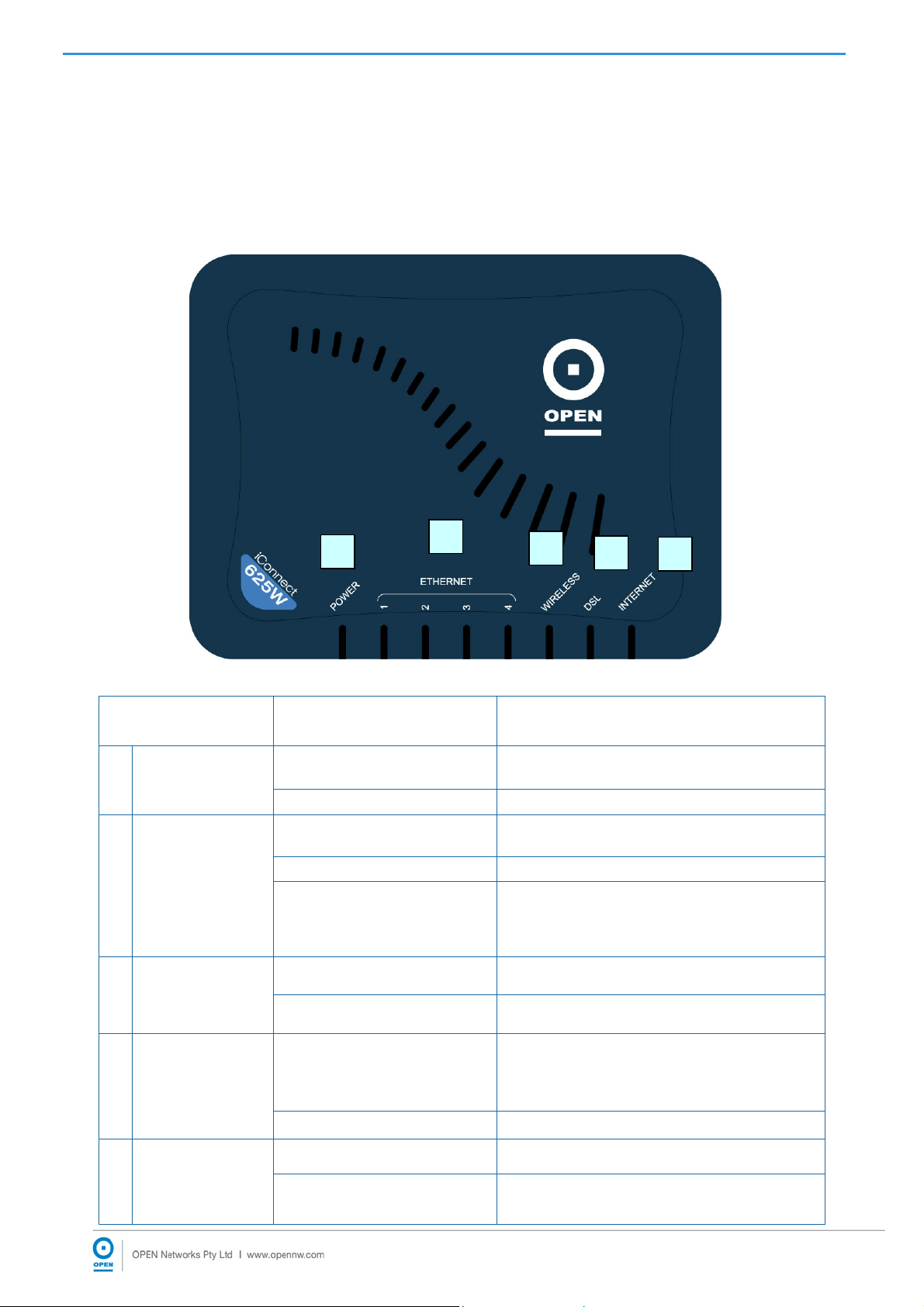
1.4.1 The Front LEDs
The LED status can help you diagnose problems with the gateway. The LED status
definitions are described in the table below.
1
2
3
4
5
LED LED Status LED Description
Power is supplied to the iConnect625W
router.
The iConnect625W Ethernet cable is
properly connected to the Ethernet port.
• No power is supplied to the
iConnect625W router;
• No Ethernet connection;
• Wrong type of Ethernet cable used.
1
2
3
POWER
ETHERNET
E1 - E4
WIRELESS
Steadily Lit Up
Off No power is supplied to the iConnect625W.
Steadily Lit Up
Flickering The Ethernet is transmitting / receiving data.
Off
Steadily Lit Up The wireless access point is enabled.
Off The wireless access point is disabled.
4
5
DSL
INTERNET
The iConnect625W is trying to establish
Flickering
Steadily Lit Up ADSL connection is established.
Steadily Lit Up The Internet connection is established.
Off The Internet connection is not established.
9
connection with the ADSL Service Provider
or the iConnect625W router is transmitting /
receiving data.
iConnect 625W ADSL Router User Guide
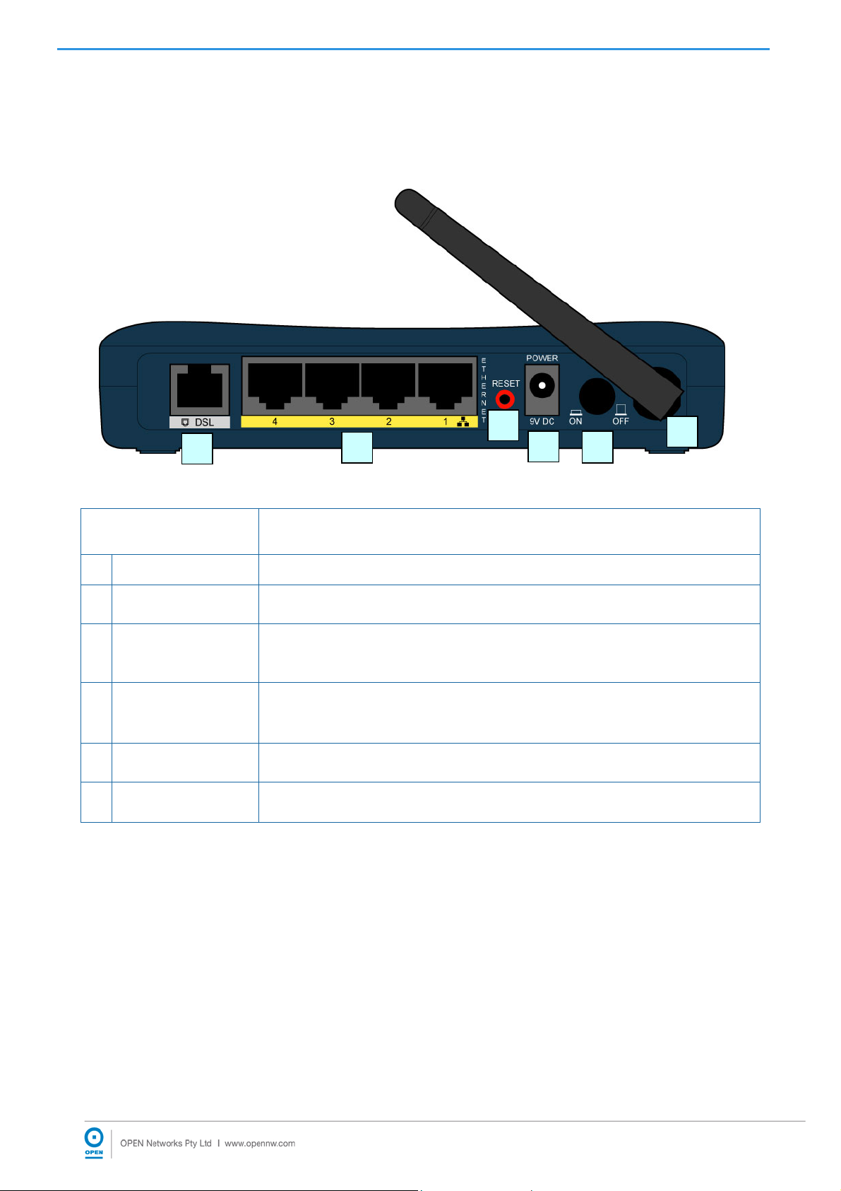
2.4.2 The Rear Ports
The rear panel holds ports that help to power up and connect the iConnect625W router to
the network.
3
5
4
1 2
6
LED Meaning
1
POWER SWITCH
2
3
4
5
6
POWER
RESET
Ethernet
ANTENNA
1 — 4
DSL
Power ON / OFF switch.
Connect the supplied power adaptor to this jack. Make sure to observe the
proper power requirements.
After the device is powered on, press it to reset the device or restore to
factory default settings.
Connect the Ethernet cable to one of the four LAN ports when connecting to
a computer or an office/home network of 10Mbps or 100Mbps.
Connect the supplied telephone cable to this port when connecting to the
ADSL/telephone network.
This is the antenna.
10

iConnect 625W ADSL Router User Guide
3. Setting Up Your iConnect625W Router
The iConnect625W router can be configured with your Web Browser. A Web Browser is
included as a standard application in the following operating systems: Linux, Mac OS,
Windows 98 ME/2000/XP/Vista. The product provides a very easy and user-friendly
interface for configuration.
Computers must have an Ethernet interface installed properly and be connected to the
router either directly or through an external repeater hub. It must also have TCP/IP
installed and configured to obtain an IP address through a DHCP server or a fixed IP
address that must be in the same subnet as the router.
The default IP address of the router is 192.168.1.254 and the subnet mask is
255.255.255.0 (i.e. any attached computer must be in the same subnet, and have an IP
address in the range of 192.168.1.1 to 192.168.1.253). The best and easiest way to
configure the computer is to get an IP address automatically from the router using DHCP.
If you encounter any problems accessing the router’s web interface it may also be
advisable to disable any kind of software firewall on your computers, as they can cause
problems accessing the 192.168.1.254 IP address of the router. Users should make their
own decisions on how to best protect their network.
Please follow the steps provided in the following section to install and configure your
computer network environment. Before you begin, it is advisable to check your computer’s
network components to ensure that the TCP/IP protocol stack and Ethernet network
adapter are installed. If they are not installed, please refer to your Windows or other
operating system manuals to install them.
11

iConnect625W ADSL/ADSL2+ Router User Guide
3.1 Default Settings
This section will guide you through your iConnect625W router configuration via the web
interface. The iConnect625W router is shipped with a standard PPP configuration.
The following table lists the default settings for your iConnect625W router. These settings
may change depending on your ISP. Please check with your ISP for more information.
Setting Default Value
Login Username
Login Password
WAN
DHCP Configuration
root
øP3N (the first character is a zero: zero-P-3-N)
Username
Password
Protocol
VPI
VCI
DHCP Server function is set to Enabled.
Start IP
End IP
Lease Time
<blank> Enter your username as
supplied by your ISP.
<blank> Enter your password as
supplied by your ISP.
PPPoE
The PPPoE function is enabled to
automatically get the WAN port from
the ISP but you have to set the
username and password first for this
to happen.
8
35
192.168.1.100
192.168.1.200
604800 seconds (or 7 days)
Management IP
(LAN)
If you ever forget your login password, you may press the RESET button for
up to 10 seconds to restore the factory default settings.
TIP
IP address
Subnet Mask
IP addresses
for distribution
to PCs
Ensure that your computer is configured for DHCP mode and that proxies
are disabled on your browser.
You must also ensure that Java Script support is enabled in the browser
settings so that the browser does not display a login redirection screen.
If any screen other than the Login screen appears, you may need to delete
your temporary Internet files, i.e. basically flush cached web page(s).
192.168.1.254
255.255.255.0
101 IP addresses continuing from
192.168.1.100 through 192.168.1.200.
12
iConnect625W ADSL/ADSL2+ Router User Guide
3.2 Factory Default Settings
You can restore your Factory Defaults by resetting the iConnect625W to the default
configuration.
Follow the steps below to restore the Factory Default Settings.
Step 1: Ensure that the iConnect625W router has been powered on for a minimum of
10 seconds.
Step 2: Using a blunt implement such as a pencil or paperclip, press the Reset button
for 10 seconds.
During this time, the reset is in progress. DO NOT power the iConnect625W off
whilst it resets.
Step 3: After 10 seconds, you may release it. The iConnect625W will be reset to its
factory defaults once the indicator lights have returned to green (non-blinking).
13

iConnect625W ADSL/ADSL2+ Router User Guide
3.3 Logging Into Your iConnect625W
Use the following procedure to log into your iConnect625W router.
Step 1: Open a web browser, and enter the following address in the Address bar:
http://192.168.1.254, then click Go. The following appears:
Step 2: Enter the username and password of root and øP3N (zero-P-3-N) in the User
name and Password fields. These fields are case sensitive .
Step 3: Click the Log In button.
Congratulations! You have now successfully logged into the iConnect625W router!
If you have problems logging into the router, please refer to Section 4 to configure
your network connection.
14
iConnect625W ADSL/ADSL2+ Router User Guide
4. PC Network Connection
This section demonstrates the steps required to configure your network connections for
the DHCP server to obtain an IP address automatically and to activate DNS Configuration,
depending on your PC's Operating System (OS).
4.1 Configuring Network Computers Using Windows XP
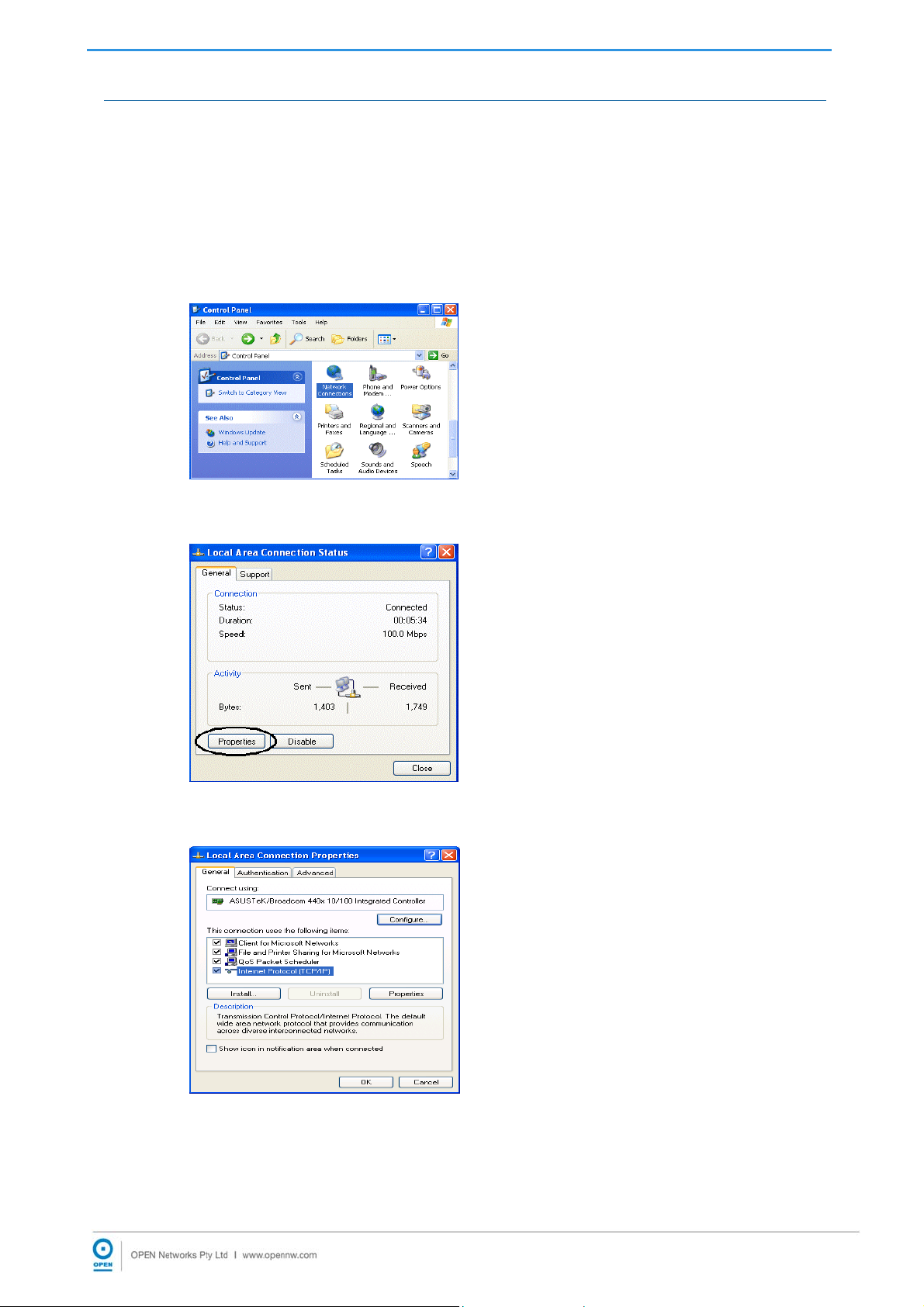
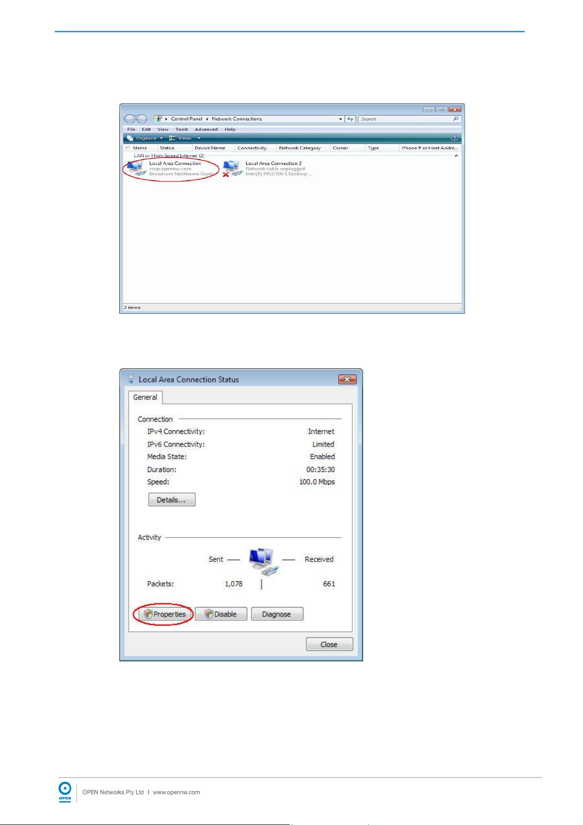
Step 1: Click Start / Control Panel (in Classic View). From the Control Panel window,
double-click Network Connections. The following appears:
Step 2: Double-click the Local Area Network connection name required.
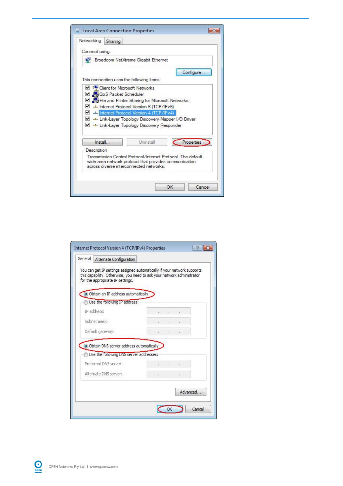
Step 3: Click Properties. The following appears:
Step 4: Ensure the General tab is active, and highlight Internet Protocol (TCP/IP),
then click Properties. The following appears:
15

iConnect625W ADSL/ADSL2+ Router User Guide
Step 5: Highlight the Obtain an IP address automatically and the Obtain DNS server
address automatically radio buttons, then click OK to complete the
configuration.
16
iConnect625W ADSL/ADSL2+ Router User Guide
4.2 Configuring Computers in Windows 2000
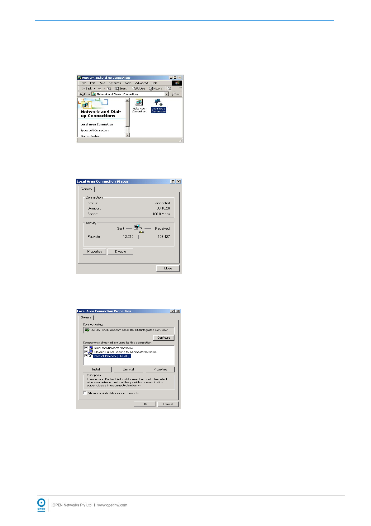
Step 1: Click Start / Settings / Control Panel. From the Control Panel window,
double-click Network and Dial-up Connections. The following appears:
Step 2: Double-click the Local Area Connection name as required. The following
appears:
Step 3: From the Local Area Connection Status window, click Properties. The
following appears:
Step 4: Highlight Internet Protocol (TCP/IP) and click Properties. The following
appears:
17

iConnect625W ADSL/ADSL2+ Router User Guide
Step 5: Highlight the Obtain an IP address automatically and the Obtain DNS server
address automatically radio buttons and click the OK button to complete the
configuration.
18
iConnect625W ADSL/ADSL2+ Router User Guide
4.3 Configuring Computers In Windows 98/ME
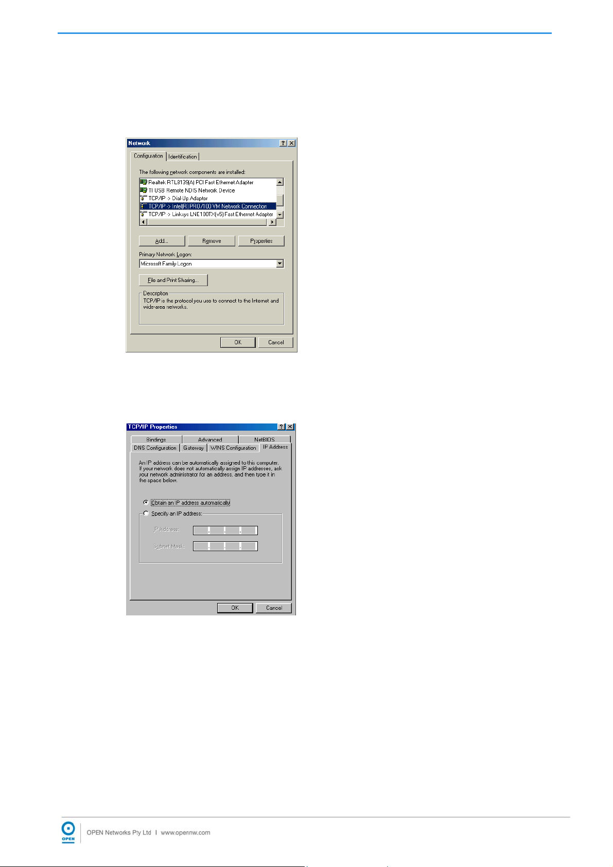
Step 1: Click Start / Settings / Control Panel. From the Control Panel window,
double-click Network and highlight the Configuration tab to make it active.
The following appears:
Step 2: Highlight TCP / IP -> NE2000 Compatible, or the name of any Network
Interface Card (NIC) in your PC, and click the Properties button. The following
appears:
Step3: Highlight the IP Address tab to make it active, then highlight the Obtain an IP
address automatically radio button.
Step 4: Highlight the DNS Configuration tab to make it active. The following appears:
19

iConnect625W ADSL/ADSL2+ Router User Guide
Step 5: Highlight the Disable DNS radio button, then click the OK button to complete
the configuration.
20
iConnect625W ADSL/ADSL2+ Router User Guide
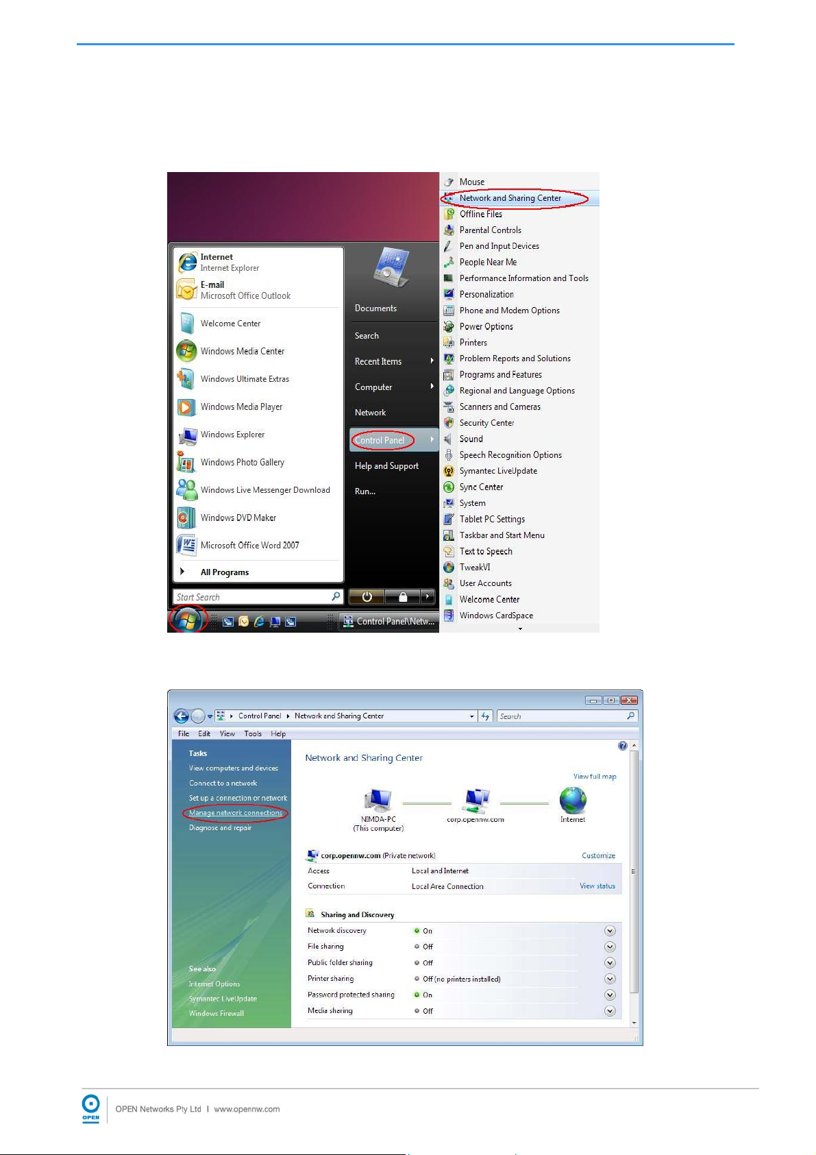
4.4 Configuring Computers In Windows Vista
Step 1: Click Windows logo / Control Panel / Network and Sharing Center as
shown:
Step 2: The following page appears. Click the Manage network connections link.
21
iConnect625W ADSL/ADSL2+ Router User Guide
Step 3: The Network Connections page appears. Double click on the active Local
Area Connection icon.
Step 4: The Local Area Connection Status page appears. Click the Properties
button.
Step 5: Under the Local Area Connection Properties page, highlight TCP/IPv4 and
click the Properties button.
22
iConnect625W ADSL/ADSL2+ Router User Guide
Step 6: Highlight the Obtain an IP address automatically and the Obtain DNS server
address automatically radio buttons and click the OK button to complete the
configuration.
23

iConnect625W ADSL/ADSL2+ Router User Guide
5. Understanding The Web Interface
5.1 Web Interface Components
The buttons, commands and menus make up the browser-based user interface. Please
read the following carefully before you commence configuration of the iConnect625W
router.
5.1.1 Buttons
Please take note of the definitions for the buttons as follows:
Apply
o Click to implement configuration changes. Clicking the Apply button does
not save the changes when the router is restarted.
Cancel
o Click the Cancel button to revert to the last saved configuration.
5.1.2 Menus
At the configuration homepage, the navigation tabs at the top of the screen directs you to
the desired configuration page.
There are seven menu items/tabs on the web interface. These include:
Home
Setup
Advanced
Wireless
Tools
Status
Help
The functions for each menu tab are described in detail in the following sections.
24
iConnect625W ADSL/ADSL2+ Router User Guide
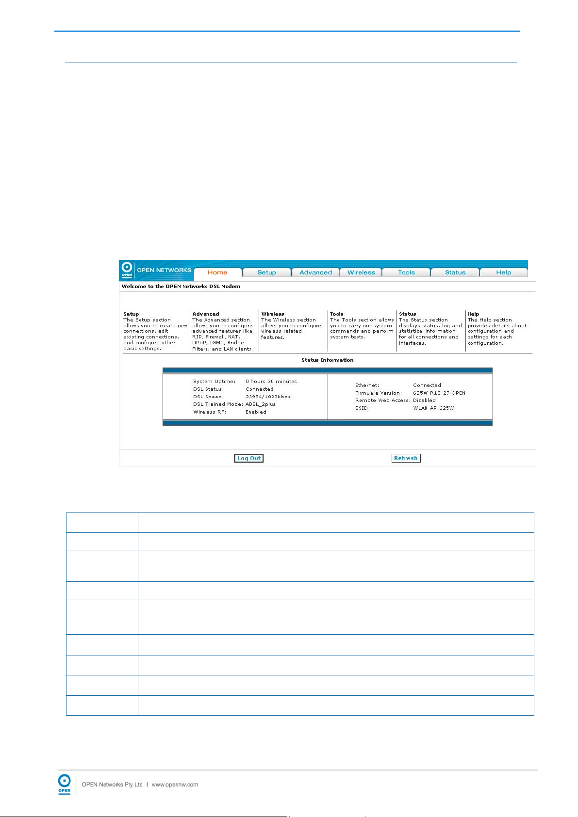
6. Home
The Home page allows access to all the menu tabs for iConnect625W configuration. Its
basic layout consists of a page selection list of option tabs across the top of the browser
window.
The centre part of the screen provides descriptions of the option tabs supported on the
web interface pages.
The lower centre part of the page displays the iConnect625W status, connection
information, firmware version and other useful information.
Step 1: To access the Home page, click the Home tab at the top of the screen. The
following appears:
The following table provides a brief description of each of the tabs and their functions.
Tab Function
Setup
Advanced
Wireless
Tools
Status
Help
Configuration of new and existing LAN and WAN settings.
Configuration of advanced options within the iConnect625W such as
SNTP, routing and filtering.
Configuration of wireless features.
Access tools and diagnostics to assist in debugging.
Status views of the modem network to all connections and interfaces.
View the extensive online Help topics.
Buttons Function
Log Out
Refresh
Click on this button to log out of the router.
Clicking on this button refreshes the details on the screen.
25
iConnect625W ADSL/ADSL2+ Router User Guide
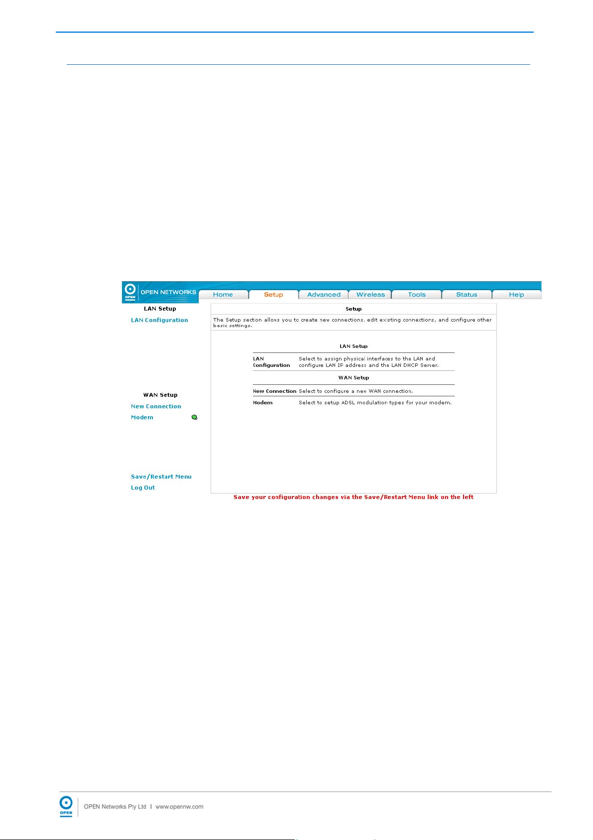
7. Setup
The Setup page consists of two subsections: LAN Setup and WAN Setup. Using the
appropriate links provided on the left menu, you can configure these settings as required.
The LAN Setup consists of LAN configuration. This is where local hosts are connected.
The iConnect625W router is configured to automatically provide all the hosts on the LAN
network with IP addresses.
The WAN Setup consists of the setup of various connection types: PPPoA, PPPoE,
Static, DHCP, Bridged connection, CLIP connection and modem setups. The WAN
interface is also referred to as a broadband connection. It is different for every WAN
service provider used.
Step 1: To access the setup page, click the Setup tab on the top navigation panel. The
following page appears:
Refer to the following sections on how to configure LAN and WAN Setups.
26

iConnect625W ADSL/ADSL2+ Router User Guide
7.1 LAN Setup
By default, your iConnect625W has the DHCP server (LAN side) enabled. If you already
have a DHCP server running on your network, you must disable one of them. If you
connect a second DHCP server into the network, you will experience network errors and
the network will not function normally.
7.1.1 LAN Configuration
The LAN Group Configuration allows you to configure settings for each defined LAN
group. You can view the status of advanced services that can be applied to this LAN
group. A green status indicates that the services have been enabled, while a red status
indicates that the service is currently disabled.
The iConnect625W provides LAN Configuration for multiple LAN groups. Up to five LAN
Groups are supported:
LAN Group 1
LAN Group 2
LAN Group 3
LAN Group 4
LAN Group 5
The LAN interfaces include the following:
Ethernet1;
WLAN (Primary SSID);
SSID1;
SSID2;
SSID3
It is possible to assign any LAN interface to any bridge group but the Ethernet interface
needs to be in LAN Group 1.
The following interfaces are not valid until multiple SSID is enabled and the
secondary SSIDs are configured:
SSID1 (corresponds to the first secondary SSID)
SSID2 (corresponds to the second secondary SSID)
SSID3 (corresponds to the third secondary SSID)
To setup LAN Configuration, follow the steps below.
Step 1: From the top menu, click the Setup tab.
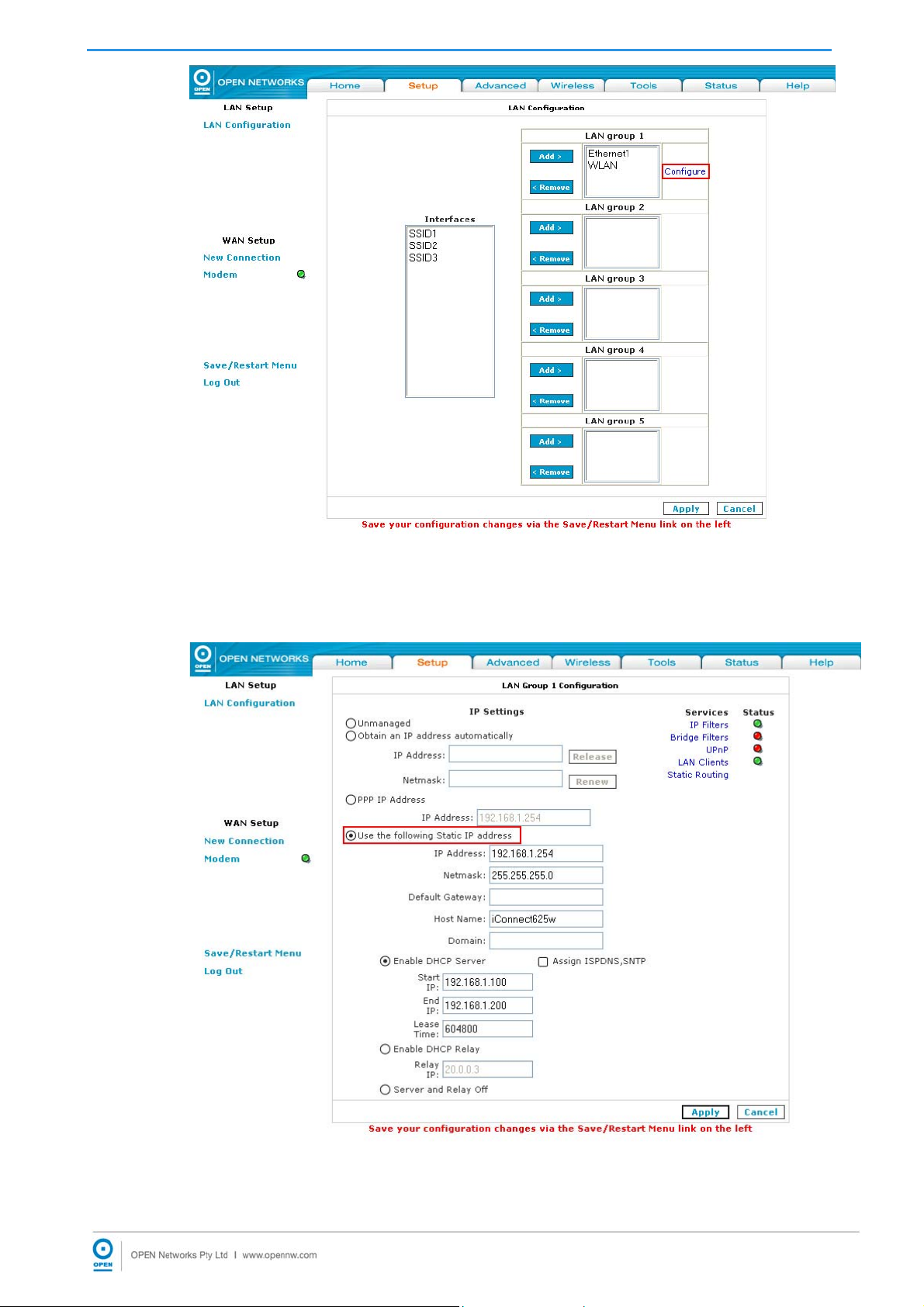
Step 2: Click the LAN Configuration link on the left menu. The following appears:
27
iConnect625W ADSL/ADSL2+ Router User Guide
Step 2: The Ethernet interface is defaulted to LAN Group 1 and should always remain
in this group. Click the Configure link within the LAN Group 1 box. The LAN
Group 1 Configuration page appears:
Step 3: The Use the following Static IP address radio button is highlighted by default.
The default IP Address field is set to: 192.168.1.254. Change this
28

iConnect625W ADSL/ADSL2+ Router User Guide
field to a different IP Address, if required.
Step 4: The default Netmask field is set to: 255.255.255.0.
Step 5: The Enable DHCP Server radio button is highlighted by default. Enter a
different Start IP in the field if the default value: 192.168.1.100 does not apply.
This address is the beginning of the range from which the DHCP Server starts
issuing IP addresses.
Step 6: Enter the End IP field if the default value: 192.1.168.200 does not apply. This
address is the end of the range from which the DHCP Server issues IP
addresses.
Step 7: The Lease Time field is defaulted to 604800 seconds (or 7 days).
Step 8: Click the Apply button.
Step 9: To save your configuration, please refer to the section under Save / Restart
Menu.
29

iConnect625W ADSL/ADSL2+ Router User Guide
The following table lists the LAN Group Configuration fields and their definitions.
Field Definition
Unmanaged
Obtain an IP
Address
Automatically
PPP IP Address
Use the
Following Static
IP Address
Unmanaged is a state when the LAN group is not configured
and no IP address has been assigned to the bridge.
Highlight the radio button to select this option if the
iConnect625W router is acting as a DHCP client. When this
option is enabled, your iConnect625W router will request an
IP address from the DHCP server on the LAN side.
IP Address
You can retrieve or renew an IP address
from the DHCP server using the Release
and Renew buttons.
Netmask
This is the subnet mask of your
iConnect625W router.
Check this checkbox if PPP is providing addressing. The IP
address should be different from, but in the same netmask as
the WAN-side IP address.
This is the default setting. It enables you to change the IP
address of the iConnect625W router.
IP Address
Enter a static IP address. The default IP
address for the iConnect625W router is
192.168.1.254.
Netmask
Default Gateway
Host Name
Domain
Enter the static subnet mask. The default
Netmask for the iConnect625W router is
255.255.255.0. This subnet allows the
router to support 254 users. If you want
to support a larger number of users, you
can change the subnet mask.
The default gateway is the routing device
used to forward all traffic that is
addressed to a station within the local
subnet. Enter the default gateway as
specified by your ISP. Otherwise leave
this field blank and it will be automatically
populated when an ISP connection is
made.
The host name is used in conjunction
with the domain name to uniquely identify
your iConnect625W router. The
hostname can be any alphanumeric
character that does not contain spaces.
The domain name is used in conjunction
with the host name to uniquely identify
the iConnect625W.
Enable DHCP
Server
Highlighting this option turns on the DHCP server. This needs
to be disabled if a DHCP server is already running on the
LAN. The DHCP server (LAN side) is defaulted to Enabled.
30

iConnect625W ADSL/ADSL2+ Router User Guide
Field Definition
Assign ISPDNS,
SNTP
Enables/disables the Assign ISPDNS,
SNTP feature. The default is set to
disabled.
Start IP
This address is the beginning of the range
from which the DHCP server starts issuing
IP addresses. You need to ensure the
iConnect625W Management IP Address
and any statistically defined addresses
are not within the DHCP start and end
address ranges. The default Start IP
address is 192.168.1.100.
End IP
This is where the DHCP server stops
issuing IP addresses. The ending address
cannot exceed a subnet limit of 253. This
means that the maximum value for the
default gateway is 192.168.1.254. If the
DHCP server runs out of DHCP
addresses, users do not get access to
network resources. If this happens, you
can increase the End IP addresses (to the
limit of 254) or reduce the lease time.
Enable DHCP
Relay
Server and Relay
Off
Lease Time
The Lease Time is the amount of time that
a network user is allowed to maintain a
network connection to the router using the
dynamic IP address. The client will
automatically renew the address after this
time has elapsed or a new IP address is
issued. If the LAN computer does not
renew the address after the lease period,
the lease information will be removed from
the DHCP database. This database can
be viewed under Tools>DHCP Clients.
The lease time is in units of seconds.
The default value is set to 604800
seconds (or 7 days).
Highlighting this option configures the iConnect625W to
forward the DHCP request to a remote DHCP server. Enter
the remote DHCP server address in the Relay IP field.
Relay IP
The IP address of the DHCP relay server.
This will disable the iConnect625W's DHCP server and relay
functionality.
31

iConnect625W ADSL/ADSL2+ Router User Guide
7.2 Setting Up a WAN Connection
A new WAN connection is a virtual connection over the physical DSL connection. Your
iConnect625W can support up to 8 different (unique) virtual connections. If you have
multiple different virtual connections, you may need to use the static and dynamic routing
capabilities of your iConnect625W to pass data correctly.
Before the router can pass any data between the LAN and WAN interfaces, the WAN
Setup must be configured and you must ensure that you have a DSL connection.
Depending on your ISP, you will need some or all of the information outlined below before
you can properly configure the WAN Setup.
The iConnect625W supports the following connection types:
PPPoE
PPPoA
Bridged
Static
DHCP
CLIP
Follow the steps to access the Setup page.
Step 1: To access the WAN Setup, click the Setup tab. The following page appears:
Step 2: Click on New Connection or Modem to setup your WAN configuration.
The following sections will provide steps on how to configure each connection type.
32

iConnect625W ADSL/ADSL2+ Router User Guide
7.2.1 PPPoE Connection Setup
PPP, or Point-to-Point Protocol, is a method of establishing a network connection/session
between network hosts. It provides secure login, and traffic metering among other
advanced features.
PPPoE (PPP over Ethernet) is a protocol for encapsulating PPP frames in Ethernet
frames. It provides the ability to connect to a network of hosts over a simple bridging
access device to a remote access concentrator.
It was designed to bring the security and metering benefits of PPP to Ethernet
connections such as DSL. PPPoE allows ADSL users to be authenticated by the ISP’s
systems. Most broadband connections are Ethernet, hence PPP over Ethernet. It also
allows for ISPs to provide multiple services over multiple PPP sessions, i.e., rated
services, broadband specific content (movies, etc.), metered services, etc.
To configure PPPoE connection, follow the steps provided below.
Step 1: To begin, click the Setup tab on the top menu. Click the New Connection link.
The default PPPoE Connection Setup page appears:
Step 2: MyConnection is the default name displayed in the Name field. Enter a unique
name for your PPPoE connection. The name must not have spaces and cannot
begin with numbers.
Step 3: From the Type drop-down list, PPPoE is the default setting.
Step 4: The NAT and Firewall checkboxes are enabled by default under the Options
field. Leave these in the default mode.
33

iConnect625W ADSL/ADSL2+ Router User Guide
NAT enables the IP address on the LAN side to be translated to IP address on
the WAN side. If NAT is disabled, you cannot access the Internet.
Step 5: If you want to enable VLAN, refer to the table at the end of this section as a
reference to configure the following fields:
Sharing: Select VLAN to enable the VLAN ID and Priority Bits fields.
VLAN ID: Enter the VLAN ID.
Priority Bits: Select the Priority Bits of the VLAN.
Step 6: Enter your Username and Password in the respective fields under the PPP
Settings section as shown, as provided by your ISP.
Step 7: In the PVC Settings section, enter the values for the VPI and VCI if they differ
from the default values: 8 and 35 respectively, as provided by your ISP.
If you need to use the VPI and VCI values in an existing connection, you will
need to open it and edit the settings. It is not possible to have more than one
connection using the same VPI/VCI values.
Step 8: Select the Quality of Service (QOS). Leave the default value as is if you are
unsure or if the ISP did not provide this information.
Step 9: Click the Apply button and the Save / Restart Menu link on the left menu. The
following screen appears:
34

iConnect625W ADSL/ADSL2+ Router User Guide
Step 10: Click the Save All button. The following screen appears. Click the OK button
to save the settings.
Step 11: MyConnection has been created for this connection in the left-hand menu.
You can connect, disconnect, apply, delete or cancel this connection using the
buttons at the bottom of the MyConnection page.
35

iConnect625W ADSL/ADSL2+ Router User Guide
The following table lists the PPPoE Connection Setup page fields and describes each of
the options:
Field Description
Network Address Translation is a feature that enables you
NAT
to use private IP addresses on your computer or your LAN.
This is set to Enabled by default for standard operation.
Firewall
VLAN Settings
This is set to Enabled by default for standard operation.
The following options are available:
• Disable: Disables connection sharing;
• Enable: Enables connection sharing;
Sharing
• VLAN: The VLAN ID and Priority Bits
fields are activated when VLAN is
selected, which enables you to create
VLAN.
Multiple connections over the same PVC
are supported, which requires the WAN
network to have VLAN support and for the
DSLAMS and routers on the ISP to handle
VLAN Tags.
VLAN ID
Extended support is also available, which
allows multiple connections to be placed
over the single PVC without VLAN support
(VLAN Tag of 0 in this special case). In
this mode of operation, a received packet
is flooded on all the connections that
reside over it.
PPP Settings
Priority is given to a VLAN connection
Priority Bits
from 0-7. All packets sent over the VLAN
connection have the priority bits set to the
configured level.
Each of the fields for PPP Settings is described as follows.
Your user name for the PPPoE access
provided by your ISP. This field is
Username
alphanumeric and the maximum limit is
64 characters. It cannot start with a
number.
Your password for the PPPoE access
provided by your ISP. This field is
Password
alphanumeric and the maximum number
of characters allowed is 128 characters.
It cannot start with a number.
36

iConnect625W ADSL/ADSL2+ Router User Guide
Field Description
Specifies that the PPPoE connection
should disconnect if the link has no
activity detected for n seconds. This field
is in conjunction with the On-Demand
Idle Timeout
feature and is enabled only when the On
Demand checkbox is checked. To
ensure that the link is always active,
enter a 0 in this field. You can also enter
a value larger than 10 (secs).
When the On Demand option is not
enabled, this value specifies the time to
wait without being connected to your
Keep Alive
provider before terminating the
connection. To ensure that the link is
always active, enter a 0 in this field. You
can also enter any positive integer
values into this field.
This defines the authentication protocol
for your ISP. This is set to Auto by
default.
Auto
The authentication is
automatic.
Authentication
Stands for Challenge
CHAP
Handshake Authentication
Protocol.
MTU
On-Demand
Default
Gateway
PAP
Stands for Password
Authentication Protocol.
This is the Maximum Transmissi on Unit
that the DSL connection can transmit. It
is a negotiated value that packets no
more than n bytes can be sent to the
service provider. The PPPoE interface
default is 1492 (max) and PPPoA is
1500 (max). The minimum MTU value is
64.
If selected, this enables on-demand
connectivity to the Internet. Your
Internet connection is activated when
traffic is generated from LAN clients.
The connection disconnects if no activity
is detected after the specified timeout
value. When checked, this field enables
the following fields:
• Idle Timeout;
• Host Trigger;
• Valid Rx.
If checked, this WAN connection acts as
the default gateway to the Internet.
37

iConnect625W ADSL/ADSL2+ Router User Guide
Field Description
This feature is enabled by default. It
forces all TCP traffic to conform with the
Enforce MTU
PPP MTU by changing the TCP
maximum segment size to the PPP
MTU. If it is disabled, you may have
issues accessing some Internet sites.
Debug
Check this checkbox to enable PPPoE
connection debugging facilities.
PPP Unnumbered is a special feature. It
enables the ISP to designate a block of
PPP
Unnumbered
public IP addresses to the customer
where it is statically assigned on the LAN
side. PPP Unnumbered is essentially like
a bridged connection.
This field is used in conjunction with the
On-Demand feature and is enabled only
when the On Demand field is checked.
When the On-Demand feature is
enabled and Valid Rx is unchecked, only
packets going from the LAN side to the
WAN side keep the link active. After the
iConnect625W times out, no packets can
Valid Rx
be received from the WAN side to the
LAN side.
If Valid Rx is checked, the incoming
packets can keep the PPPoE WAN
connection active. There is one
condition: these incoming packets
should belong to a connection initiated
from a LAN-side device.
38

iConnect625W ADSL/ADSL2+ Router User Guide
Field Description
This field is used in conjunction with the
On-Demand feature and is enabled only
when the On Demand field is checked.
There are 3 types of packets:
• LAN packets (Type 1): packets
are generated by the
iConnect625W from the LAN to
the WAN.
• Proxied packets (Type 2):
packets are generated by the
iConnect625W after receiving
packets from the LAN side, such
as DNS Proxy.
• Locally generally packets (Type
3): packets are generated by the
iConnect625W such as Voice,
SNMP, etc.
When the On-Demand feature is
enabled and Host Trigger is unchecked,
only the flow of Type 1 packets keeps
Host Trigger
the link active, i.e. if the iConnect625W
has not received Type 1 packets for x
amount of time (as specified in the
Timeout field), the connection times out.
If Host Trigger is checked, Type 2 and
Type 3 packets can keep the link active
as well. You can configure the packets
using the Trigger Traffic page, which is
accessed by clicking the Configure
button next to Host Trigger.
The following fields can be used to
identify the traffic of Type 2 and/or Type
3 packets that will keep the link alive:
• Source Port (the character * is
used to denote any port);
• Destination Port (the character *
is used to denote any port);
• Protocol (TCP, UDP, ICMP, or
Specify the protocol number)
The LAN field is associated with the PPP
Unnumbered field and is enabled when
LAN
the latter field is checked. You can
specify the LAN group the packets need
to go to when the PPP Unnumbered
feature is activated.
39

iConnect625W ADSL/ADSL2+ Router User Guide
Field Description
The Permanent Virtual Circuit is a fixed virtual circuit
PVC Settings
between two users. It is the public data network equivalent
to a leased line. No call setup or clearing of procedures are
needed.
The VPI (Virtual Path Identifier) defines the
virtual path settings for the ADSL
VPI
connection between you and your ISP.
The VPI value entered here must be based
on the information provided by your ISP.
The VCI (Virtual Channel Identifier) defines
the virtual channel settings for the ADSL
VCI
connection between you and your ISP.
The VCI value entered here must be based
on the information provided by your ISP.
QoS is a characteristic of data transmission
that measures how accurately and how
quickly a message or data is transferred
from a source host to a destination host
QoS
over a network. The 3 QoS options are:
• UBR, CBR and VBR.
The QoS selected must be based on the
information provided by your ISP. This is
set to UBR by default.
UBR is the bandwidth
allocation service that does
not guarantee any throughput
UBR
levels and uses only available
bandwidth. UBR is often used
when transmitting data that
can tolerate delays.
CBR is the bandwidth service
that requires the user to
determine a fixed bandwidth
requirement at the time the
CBR
connection is set up so that
the data can be sent in a
steady stream. CBR service is
often used when transmitting
fixed-rate uncompressed
video.
40

iConnect625W ADSL/ADSL2+ Router User Guide
Field Description
VBR is the bandwidth service
that allows users to specify a
throughput capacity (i.e., a
peak rate) and a sustained
VBR
rate but data is not sent
evenly. VBR is often used
when transmitting compressed
packetized voice and video
data, such as video
conferencing.
The Peak Cell Rate, measured in cells/sec,
PCR
is the cell rate that the source may never
exceed.
Sustained Cell Rate, measured in cells/sec,
SCR
is the average cell rate over the duration of
the connection.
The Maximum Burst Size is a traffic
MBS
parameter that specifies the maximum
number of cells that can be transmitted at
the PCR.
CDVT
The Cell Delay Variation Tolerance is the
maximum amount of cell delay variation
that can be accommodated. Cell delay
variation measures the random inter-arrival
times of cells within an ATM connection
due to cell transfer delay caused by
buffering, multiplexing and so on.
41

iConnect625W ADSL/ADSL2+ Router User Guide
Field Description
Connect
The overall operation of the auto-sensing
PVC feature relies on end-to-end OAM
pings to defined PVCs. There are two
groups of PVCs:
• Customer default PVCs - defined by
the ISP and the backup PVCs. It
must have 0/35 as the first default
PVC.
• Backup list of PVCs - it must be of
the following VPI/VCI: 0/35, 8/35,
0/43, 0/51, 0/59, 8/43, 8/51 and
8/59. These are defined in XLM and
are configurable.
The Auto-sensing PVC feature itself is also
configurable in that the auto-search
mechanism can be disabled.
Upon DSL synchronization, end-to-end
OAM pings will be conducted for every
Auto PVC
defined PVC. The result of the pings will be
recorded in an array for later use to
determine the usability of the particular
PVC for connectivity. This list helps the
PVC to manage the available PVC for use,
and needs to be synchronised with
connections made without auto-sensing
PVC.
Once the connection is established, the
PVC is stored in flash as the default PVC.
Therefore upon reboot, this PVC is
automatically chosen as the PVC for that
connection.
The list of default PVCs and backup PVCs
need to be global for the management of all
connections, non auto-sensing PVC
connection and auto-sensing connections.
These lists allow end users to establish
connectivity without keeping track of the
PVC used.
Click Connect to authenticate to your ISP via PPPoE and
connect to the Internet.
Disconnect
Apply
Delete
Cancel
Click Disconnect to break your Internet connection.
Applies the changes made to the connection.
Deletes the connection.
Cancels the changes made to the connection.
42

iConnect625W ADSL/ADSL2+ Router User Guide
7.2.2 PPPoA Connection Setup
PPPoA (Point-to-Point Protocol over ATM) is a network protocol for encapsulating PPP
packets in ATM cells that are carried over the DSL line. It is used mainly with ADSL
services and is compliant with RFC 2364.
PPP is a method of establishing a network connection/session between network hosts. It
usually provides a mechanism of authenticating users. Logical Link Control (LLC) and
Virtual Circuit (VC) are two different methods of encapsulating the PPP packet. Contact
your ISP to determine which encapsulation is being used on your DSL connection.
To configure PPPoA connection, follow the steps below.
Step 1: To begin, click the Setup tab on the top menu. Click the New Connection link.
The default PPPoE Connection Setup page appears:
Step 2: Enter a unique name for your PPPoA connection in the Name field. The name
must not have spaces and cannot begin with numbers.
Step 3: From the Type drop-down list, select PPPoA. The default PPPoA page
appears:
43

iConnect625W ADSL/ADSL2+ Router User Guide
Step 4: The NAT and Firewall checkboxes are checked by default under the Options
field. Leave these in the default mode.
Step 5: If you want to enable VLAN, refer to the table at the end of this section as a
reference to configure the following fields:
Sharing: Select VLAN to enable the VLAN ID and Priority Bits fields.
VLAN ID: Enter the VLAN ID.
Priority Bits: Select the Priority Bits of the VLAN.
Step 6: In the PPP Settings section, select the Encapsulation Type (LLC or VC) by
highlighting the appropriate radio button. The default is set to VC. Your ISP
should be providing the Encapsulation Type. If you are unsure, maintain the
default mode.
Step 7: Enter your Username and Password in the respective fields as shown below,
as provided by your ISP.
44

iConnect625W ADSL/ADSL2+ Router User Guide
Step 8: In the PVC Settings section, enter the VPI and VCI values, as provided by your
ISP. These are defaulted to '8' and '35', respectively,
If you need to use the VPI and VCI values in an existing connection, you will need to open
it and edit the settings. It is not possible to have more than one connection using the
same VPI/VCI values.
Step 9: Select the QoS. Leave the default value if you are unsure or if the ISP did not
provide this information.
Step 10: Click the Apply button.
Step 11: To save your configuration, please refer to the section under Save / Restart
Menu.
The following table lists the PPPoA Connection Setup screen fields and describes each of
the options:
Field Description
NAT
Firewall
PPP Settings
Network Address Translation is a feature that enables you to use
private IP addresses on your computer or your LAN. This is set to
Enabled by default for standard operation.
Select to enable security for this connection. This is set to Enabled by
default for standard operation.
Each of the fields for PPP Settings is described as follows.
Encapsulation is the technique used by layered
Encapsulation
protocols in which a layer adds header information
to the protocol data unit (PDU) from the layer
above. Two options are provided: LLC and VC.
45

iConnect625W ADSL/ADSL2+ Router User Guide
Field Description
With LLC encapsulation, a link control
header is added to the Ethernet packet that
LLC
identifies the protocol type (Ethernet). This
allows multiple protocols to be transmitted
over the ATM VC.
With VC multiplexing, .no link control header
VC
is needed as the ATM VC is assumed to be
carrying a single protocol.
Your user name for the PPPoA access provided by
Username
your ISP. This field is alphanumeric and the
maximum length is 64 characters. It cannot start
with a number.
Your password for the PPPoA access provided by
Password
your ISP. This field is alphanumeric and the
maximum length is 128 characters. It cannot start
with a number.
Specifies that the PPPoA connection should
disconnect if the link has no activity detected for n
seconds. This field is in conjunction with the On-
Idle Timeout
Demand feature and is enabled only when the On
Demand checkbox is checked. To ensure that the
link is always active, enter a 0 in this field. You can
also enter a value larger than 10 (secs).
Keep Alive
Authentication
MTU
On-Demand
Default
Gateway
When the On Demand option is not enabled, this
value specifies the time to wait without being
connected to your provider before terminating the
connection. To ensure that the link is always active,
enter a 0 in this field. You can also enter any
positive integer value in this field.
This defines the authentication protocol for your
ISP. This is set to Auto by default.
Auto
CHAP
PAP
The authentication is automatic.
Stands for Challenge Handshake
Authentication Protocol.
Stands for Password Authentication
Protocol.
This is the Maximum Transmissi on Unit that the
DSL connection can transmit. It is a negotiated
value that packets no more than n bytes can be
sent to the service provider. The PPPoE interface
default is 1492 (max) and PPPoA is 1500 (max).
The minimum MTU value is 64.
If selected, this enables on-demand mode. The
connection disconnects if no activity is detected
after the specified timeout value.
If checked, this WAN connection acts as the default
gateway to the Internet.
46

iConnect625W ADSL/ADSL2+ Router User Guide
Field Description
PVC Settings
Debug
Check this checkbox to enable PPP connection
debugging facilities.
PPP Unnumbered is a special feature. It enables
PPP
Unnumbered
the ISP to designate a block of public IP addresses
to the customer where it is statically assigned on
the LAN side. PPP Unnumbered is essentially like a
bridged connection.
The LAN field is associated with the PPP
LAN
Unnumbered field. The packets need to go through
a specific LAN group when the PPP Unnumbered
feature is activated.
The PVC Settings are not mandatory except for the VPI and VCI fields.
The VPI defines the virtual path settings for the
VPI
ADSL connection between you and your ISP. The
VPI value entered here must be based on the
information provided by your ISP.
The VCI (Virtual Channel Identifier) defines the
virtual channel settings for the ADSL connection
VCI
between you and your ISP. The VCI value entered
here must be based on the information provided by
your ISP.
Connect
Disconnect
Apply
Delete
Cancel
This field defines QoS at the ATM layer. Three
different Quality Of Service options are available in
the iConnect625W: UBR, CBR and VBR (refer to
QoS
the previous section under the PPPoE table for the
definitions). The QoS selected here must be based
on the information provided by your ISP. This is set
to UBR by default.
Click Connect to authenticate to your ISP via PPPoA and connect to
the Internet.
Click Disconnect to break your Internet connection.
Applies the changes made to the connection.
Deletes the connection.
Cancels the changes made to the connection.
For VLAN and PVC field descriptions, please refer to the table under PPPoE section.
47

iConnect625W ADSL/ADSL2+ Router User Guide
7.2.3 Static Connection Setup
A Static Connection type is used whenever an ISP provides a Static IP address. Your ISP
should provide the information for the Subnet Mask and the Gateway. Up to three
Domain Name Server (DNS) addresses can be identified. These servers would enable
you to have access to other web servers using the host name.
To configure Static connection, follow the steps provided below.
Step 1: To begin, click the Setup tab on the top menu. Click the New Connection link.
The default PPPoE Connection Setup page appears:
Step 2: From the Type drop-down list, select Static. The following page appears:
48

iConnect625W ADSL/ADSL2+ Router User Guide
Step 3: Enter a unique name for your Static connection in the Name field. The name
must not have spaces and cannot begin with numbers.
Step 4: The NAT and Firewall checkboxes are checked by default under the Options
field. Leave these in the default mode.
Step 5: Select the Encapsulation Type (LLC or VC) by highlighting the appropriate
radio button. The default is set to LLC. If you are unsure about the option, leave
the default setting as it is.
Step 6: In the IP Address field, enter your assigned IP address based on the
information provided by your ISP.
Step 7: In the Mask field, enter the Subnet Mask based on the information provided by
your ISP.
Step 8: In the Default Gateway field, enter the Default Gateway based on the
information provided by your ISP.
Step 9: In the DNS1, DNS2 and DNS3 fields, enter the Domain Name Services values
based on the information provided by your ISP.
Step 10: For the static configuration in the Mode option, the default mode is set to
Bridged. You can select the Routed connection, if this is applicable.
Step 11: In the PVC Settings section, the VPI and VCI are defaulted to 8 and 35,
respectively. Make the changes in these fields, as provided by your ISP, if
required.
If you need to use the VPI and VCI values in an existing connection, you will need to open
it and edit the settings. It is not possible to have more than one connection using the
same VPI/VCI values.
Step 12: Select the QoS. Leave the default value if you are unsure or if the ISP did not
provide this information. The PCR, SCR, MBS and CDVT fields are enabled /
disabled based depending on the selection for QoS. Your ISP should provide
these values.
Step 13: Click the Apply button.
Step 14: To save your configuration, please refer to the section under Save / Restart
Menu.
49

iConnect625W ADSL/ADSL2+ Router User Guide
The following table lists the Static Connection Setup screen fields and their definitions:
Field Description
Network Address Translation is a feature that enables you to use
NAT
private IP addresses on your computer or your LAN. This is set to
Enabled by default for standard operation.
Firewall
Static
Settings
Select to enable security for this connection. This is set to Enabled by
default for standard operation.
Each of the fields for Static Settings is described as follows.
LLC or VC and two different methods of
encapsulating multiple sessions. The default is set to
LLC.
With LLC encapsulation, a link control
header is added to the Ethernet packet that
Encapsulation
LLC
identifies the protocol type (Ethernet). This
allows multiple protocols to be transmitted
over the ATM Virtual Circuit (VC).
With VC multiplexing, no link control header
VC
is needed as the ATM VC is assumed to be
carrying a single protocol.
This is the static IP address that will be assigned to
IP Address
the WAN interface of the iConnect625W router. The
information is based on the details provided by your
ISP.
A Mask is used to determine which subnet an IP
address belongs to. This is the Subnet Mask that will
Mask
be assigned to the WAN interface of the
iConnect625W router. The information is based on
the details provided by your ISP.
Apply
Delete
Cancel
The Default Gateway is the host to which local
Default
Gateway
computers send data that is destined for a non-local
machine. On the iConnect625W router, configure the
default gateway to reach all computers that are not in
the same local IP subnet.
DNS service is used to translate a Domain Name into
DNS 1 - DNS 3
a corresponding IP address. The DNS server name
should be obtained from your ISP.
Mode
Select either the Routed or Bridged mode option.
Applies the changes made to the connection.
Deletes the connection.
Cancels the changes made to the connection.
For VLAN and PVC field descriptions, please refer to the table under PPPoE section.
50

iConnect625W ADSL/ADSL2+ Router User Guide
7.2.4 DHCP Connection Setup
Dynamic Host Configuration Protocol (DHCP) allows the iConnect625W to obtain an IP
address automatically from the server. With dynamic addressing, a device may have a
different IP address every time it connects to the network. Before configuration begins,
please check with your ISP to ensure that this mode is supported.
To configure DHCP connection, follow the steps provided below.
Step 1: To begin, click the Setup tab on the top menu. Click the New Connection link.
The default PPPoE Connection Setup page appears:
Step 2: From the Type drop-down list, select DHCP. The following page appears:
51

iConnect625W ADSL/ADSL2+ Router User Guide
Step 3: Enter a unique name for your DHCP connection in the Name field. The name
must not have spaces and cannot begin with numbers.
Step 4: The NAT and Firewall checkboxes are checked by default under the Options
field. Leave these in the default mode.
Step 5: Select the Encapsulation Type (LLC or VC) by highlighting the appropriate
radio button. The default is set to LLC. If you are unsure about the option, leave
the default setting as it is.
Step 6: If your DSL line is connected and your ISP supports DHCP, click the Renew
button to retrieve an IP address, Subnet Mask and Default Gateway address.
Alternatively, you can click the Release button at any time to release the DHCP
address.
You can renew the DHCP address at any time by clicking the Renew button. This is not
required in most cases as the process runs automatically.
Step 7: From the PVC Settings section, the VPI and VCI are defaulted to 8 and 35,
respectively. Make the changes in these fields, if required, based on the
information from your ISP.
If you need to use the VPI and VCI values in an existing connection, you will need to open
it and edit the settings. It is not possible to have more than one connection using the
same VPI/VCI values.
Step 8: Select the QoS. Leave the default value if you are unsure or if the ISP did not
provide this information.
The PCR, SCR, MBS and CDVT fields could be enabled/disabled depending
on the QoS section. Your ISP should provide these values.
Step 9: Click the Apply button.
Step 10: To save your configuration, please refer to the section under Save / Restart
Menu.
52

iConnect625W ADSL/ADSL2+ Router User Guide
The following table lists the DHCP Connection Setup screen fields and their definitions:
Field Description
Network Address Translation is a feature that enables you to use
NAT
private IP addresses on your computer or your LAN. This is set to
Enabled by default for standard operation.
Firewall
DHCP
Settings
Select to enable security for this connection. This is set to Enabled by
default for standard operation.
Each of the fields for DHCP Settings is described as follows.
LLC and VC are two different methods of
encapsulating multiple sessions. The default is set to
LLC.
With LLC encapsulation, a link control
header is added to the Ethernet packet that
Encapsulation
LLC
identifies the protocol type (Ethernet). This
allows multiple protocols to be transmitted
over the ATM Virtual Circuit (VC).
With VC multiplexing, no link control header
VC
is needed as the ATM VC is assumed to be
carrying a single protocol.
IP Address
This is the static IP address assigned by the DHCP
server.
A Mask is used to determine which subnet an IP
address belongs to. This is the Subnet Mask that will
Mask
be assigned to the WAN interface of the
iConnect625W router. The information is based on
the details provided by your ISP.
Renew
Release
Apply
Delete
Cancel
Gateway
Default
Gateway
The Gateway is the IP address of your gateway.
If this field is enabled/checked, this WAN connection
will act as the default gateway to the Internet.
It may be necessary on occasion to get a new IP address or to update
the DHCP options sent by your ISP's DHCP server. Pressing this
button renews the DHCP lease.
Clicking this button releases the current network settings from the
iConnectAccess264W router.
Applies the changes made to the connection.
Deletes the connection.
Cancels the changes made to the connection.
For VLAN and PVC field descriptions, please refer to the table under PPPoE section.
53

iConnect625W ADSL/ADSL2+ Router User Guide
7.2.5 Bridged Connection Setup
In Bridge mode, Ethernet frames are bridged over ATM VC. The Ethernet frames are
encapsulated using either LLC Encapsulation or VC Multiplexing. Since the Ethernet
packets are bridged, the router's only functionality is to pass the Ethernet packets to and
from the ISP and the local network.
Your ISP assigns the IP addresses of the local network, either statically or dynamically. If
your ISP provides bridged service, you may select the Bridged connection type.
In this setting, the NAT and firewall rules are disabled. This connection method makes the
iConnect625W act as a transparent hub and passes packets across from the WAN
interface to the LAN interface transparently.
To configure Bridge connection, follow the steps provided below.
Step 1: To begin, click the Setup tab on the top menu. Click the New Connection link.
The default PPPoE Connection Setup page appears:
54

iConnect625W ADSL/ADSL2+ Router User Guide
Step 2: From the Type drop-down list, select Bridge. The following page appears:
Step 3: Enter a unique name for your Bridged connection in the Name field. The name
must not have spaces and cannot begin with numbers.
Step 4: Select the Encapsulation Type (LLC or VC) by highlighting the appropriate
radio button. The default is set to LLC. If you are unsure about the option, leave
the default setting as it is.
Step 5: In the Select LAN field, select the appropriate LAN Group you wish to
configure for Bridge mode.
Step 6: The VPI and VCI values are defaulted to 8 and 35, respectively. Make the
changes in these fields as provided by your ISP, if required.
If you need to use the VPI and VCI values in an existing connection, you will need to open
it and edit the settings. It is not possible to have more than one connection using the
same VPI/VCI values.
Step 7: Select the QoS. Leave the default value if you are unsure or if the ISP did not
provide this information.
The PCR, SCR, MBS and CDVT fields could be enabled/disabled depending
on the QoS section. Your ISP should provide these values.
Step 8: Click the Apply button.
Step 9: To save your configuration, please refer to the section under Save / Restart
Menu.
55

iConnect625W ADSL/ADSL2+ Router User Guide
The following table lists the Bridge Connection Setup screen and their definitions:
Field Description
Each of the fields for Bridge Settings is described as follows.
LLC and VC are two different methods of
encapsulating multiple sessions. The default is set to
LLC.
With LLC encapsulation, a link control
header is added to the Ethernet packet that
Encapsulation
LLC
identifies the protocol type (Ethernet). This
allows multiple protocols to be transmitted
over the ATM Virtual Circuit (VC).
With VC multiplexing, .no link control header
VC
is needed as the ATM VC is assumed to be
carrying a single protocol.
Bridge
Settings
Select the LAN Group (as defined in the LAN
Configuration screen) for the bridged connection. The
options are:
• LAN Group 1
• LAN Group 2
• LAN Group 3
• LAN Group 4
Select LAN
• LAN Group 5
• None
Apply
Delete
Cancel
The Bridge connection is added to the LAN Group
configuration, unless you have selected the option:
None. In this case, the connection will be added to
the Interfaces box instead.
Applies the changes made to the connection.
Deletes the connection.
Cancels the changes made to the connection.
For VLAN and PVC field descriptions, please refer to the table under PPPoE section.
56

iConnect625W ADSL/ADSL2+ Router User Guide
7.2.6 CLIP Connection Setup
Classical IP Over ATM as defined in RFC1577 provides the ability to transmit IP packets
over an ATM network. CLIP support encapsulates IP in an AAL5 Packet Data Unit (PDU)
frame using RFC 1577 and it sends out an ARP request to a CLIP-enable ARP server,
which returns the ATM address.
To configure CLIP connection, follow the steps provided below.
Step 1: To begin, click the Setup tab on the top menu. Click the New Connection link.
The following page appears if no prior connection has been configured:
Step 2: From the Type drop-down list, select CLIP. The following page appears:
57

iConnect625W ADSL/ADSL2+ Router User Guide
Step 3: Enter a unique name for your Bridged connection in the Name field. The name
must not have spaces and cannot begin with numbers.
Step 4: The NAT and Firewall checkboxes are checked by default under the Options
field. Leave these in the default mode.
Step 5: In the IP Address field, enter your assigned IP address based on the
information provided by your ISP.
Step 6: In the Mask field, enter the Subnet Mask based on the information provided by
your ISP.
Step 7: In the ARP Server field, enter the ARP Server address based on the
information provided by your ISP.
Step 8: In the Default Gateway field, the Default Gateway is blank. Enter this field
based on the information provided by your ISP.
Step 9: In the PVC Settings section, the VPI and VCI values are defaulted to 8 and 35,
respectively. Make the changes in these fields, as provided by your ISP, if
required.
If you need to use the VPI and VCI values in an existing connection, you will need to open
it and edit the settings. It is not possible to have more than one connection using the
same VPI/VCI values.
Step 10: Select the QoS. Leave the default value if you are unsure or if the ISP did not
provide this information.
The PCR, SCR, MBS and CDVT fields could be enabled/disabled depending
on the QoS section. Your ISP should provide these values.
Step 11: Click the Apply button.
Step 12: To save your configuration, please refer to the section under Save / Restart
Menu.
58

iConnect625W ADSL/ADSL2+ Router User Guide
The following table lists the CLIP Connection Setup screen and their definitions:
Field Description
Network Address Translation is a feature that enables you to use
NAT
private IP addresses on your computer or your LAN. This is set to
Enabled by default for standard operation.
Firewall
CLIP
Settings
Select to enable security for this connection. This is set to Enabled by
default for standard operation.
Each of the fields for CLIP Settings is described as follows.
LLC and VC are two different methods of
encapsulating multiple sessions. The default is set to
LLC.
With LLC encapsulation, a link control
header is added to the Ethernet packet that
Encapsulation
LLC
identifies the protocol type (Ethernet). This
allows multiple protocols to be transmitted
over the ATM Virtual Circuit (VC).
With VC multiplexing, .no link control header
VC
is needed as the ATM VC is assumed to be
carrying a single protocol.
IP Address
Mask
ARP Server
The CLIP Server IP Address provided by
your ISP.
The CLIP Server Subnet Mask provided by
your ISP.
The Address Resolution Protocol (ARP)
Server IP Address provided by your ISP.
Apply
Delete
Cancel
Default Gateway
If checked, this WAN connection acts as the
default gateway to the Internet.
Applies the changes made to the connection.
Deletes the connection.
Cancels the changes made to the connection.
For VLAN and PVC field descriptions, please refer to the table under PPPoE section.
59

iConnect625W ADSL/ADSL2+ Router User Guide
7.2.7 Modify an Existing Connection
Follow the steps below to modify an existing connection.
Step 1: To begin, click the Setup tab on the top menu, and click the connection you
wish to modify from the left hand menu.
Step 2: Edit as applicable on the individual connection page.
Step 3: Click the Apply button.
Step 4: To save your configuration, please refer to the section under Save / Restart
Menu.
60

iConnect625W ADSL/ADSL2+ Router User Guide
7.2.8 Delete an Existing Connection
Follow the steps below to delete a WAN connection.
Step 1: To begin, click the Setup tab on the top menu, and click the connection you
wish to delete from the left hand menu.
Step 2: Click the Delete button on the applicable connection you wish to remove.
The changes take effect when you click Delete. However, if the iConnect625W
router configuration is not saved, these changes will be lost when you reboot the
iConnect625W router.
Step 3: To save your configuration, please refer to the section under Save / Restart
Menu.
61

iConnect625W ADSL/ADSL2+ Router User Guide
7.2.9 Modem Setup
To configure the ADSL modulation types, follow the steps below.
Step 1: To begin, click the Setup tab on the top menu. Click the Modem link. The
following page appears:
Step 2: The Modulation Type checkboxes are defaulted to the above settings as
shown. It is recommended that the default settings remain.
The iConnect625W router is pre-configured to detect the ADSL modulation type
automatically. In most cases, this screen should not be modified.
Step 3: If any modulation type has been amended, click the Apply button.
Step 4: To save your configuration, please refer to the section under Save / Restart
Menu.
62

iConnect625W ADSL/ADSL2+ Router User Guide
The following table lists the Modem screen fields and their definitions:
Field Description
There are multiple combinations of ADSL modulation modes to be selected.
No Mode
ADSL_G.dmt
ADSL_G.lite
ADSL_G.dmt.bis
ADSL_G.dmt.bis.DELT
ADSL_2plus
ADSL_2plus_DELT
ADSL re-adsl
ADSL re-adsl DELT
ADSL_ANSI_T1.413
MULTI_MODE
ADSL_G.dmt.bis_AnxM
ADSL2plus_AnxM
No mode is defaulted to disabled.
G.dmt stands for G Discrete Multi-Tone. It supports ITU-U
ADSL over POTS (G.992.1).
It support ITU-T ADSL over POTS (G.992.2)
It supports ITU-T ADSL 2 over POTS (G.992.3)
It supports ADSL G.DMT.bis DELT
It supports ITU-T ADSL 2+ over POTS (G.992.5) and
speeds up to 24Mbps.
It supports ADSL 2+ and speeds up to 24Mbps.
It supports ITU-T RE-ADSL 2 over POTS (G.992.3).
It supports ADSL re-adsl DELT.
This applies to ANSI T1.413-1998.
Multi-Mode is automatically detected.
It supports ITU-T ADSL 2 G.992.3 Annex M.
It supports ITU-T ADSL 2+ G.992.5 Annex M.
63

iConnect625W ADSL/ADSL2+ Router User Guide
8. Advanced
The iConnect625W supports a host of advanced networking and routing features including
the setup of your LAN and WAN interfaces, security, port configuration, user management,
restarting the router and plug and play capability.
In addition, it allows you to performance advanced configuration functions for existing
connection such as enabling and disabling voice, voice provision, UPnP, SNTP, SNMP
and so on.
There should be at least one WAN connection configured before implementing advanced
WAN configuration features. Similarly, at least one LAN group must be defined before
advanced LAN configuration features can be implemented.
The features include:
Universal Plug and Play (UPnP)
Simple Networking Timing Protocol (SNTP)
Simple Network Management Protocol (SNMP)
Port Forwarding
IP Filters
LAN Clients
LAN Isolation between LAN groups
Remote Web Access
Bridge Filters
Dynamic DNS Client
Internet Group Management Protocol (IGMP) Proxy
Static Routing
Dynamic Routing
Policy Database
Ingress
Egress
Shaper
SSH Access Control
To access the Advanced configuration screen, follow the steps below.
Step 1: Click the Advanced tab to access the advanced configuration features. The
following page appears:
64

iConnect625W ADSL/ADSL2+ Router User Guide
Step 2: Please refer to the sections below on how to configure the advanced features.
65

iConnect625W ADSL/ADSL2+ Router User Guide
8.1 UPnP
UPnP is a networking architecture that provides compatibility among networking
equipment, software and peripherals such as game consoles, digital cameras and other
systems that connect by TCP/IP. It can be supported on any operating system, and
boasts device-driver independence and zero-configuration networking.
UPnP is a standard that uses Internet and Web protocols to enable the iConnect625W to
plug into a network and automatically recognise each other. This feature is set to
Disabled by default in the iConnect625W.
This feature requires one active WAN connection. In the presence of multiple WAN
connections, select a connection on which the incoming traffic is present, for example, the
default WAN connection.
Follow the steps below to enable UPnP.
Step 1: From the Advanced tab, click the UPnP link on the left menu. The following
page appears:
Step 2: Check the Enable UPnP checkbox. This enables the WAN connection and LAN
connection fields.
Step 3: Select the required WAN Connection that will use UPnP by highlighting the
appropriate item from the drop-down list.
66

iConnect625W ADSL/ADSL2+ Router User Guide
Step 4: Select the LAN Connection that will use UPnP by highlighting the appropriate
item from the drop-down list.
Step 5: Click the Apply button to apply the settings.
Step 6: To save your configuration, please refer to the section under Save / Restart
Menu.
67

iConnect625W ADSL/ADSL2+ Router User Guide
8.2 SNTP
SNTP ensures that the computer clock time can be synchronised in a network of
computers to the millisecond to the public SNTP servers. It uses the UDP protocol on port
123 to communicate between clients and servers.
When the SNTP feature is enabled, your iConnect625W starts verifying the time clock
information from the primary SNTP server. If it does not get a valid response within the
Timeout period, it makes additional attempts based on the number on the value of the
Retry Count field before it moves to the Secondary SNTP server. If there is no valid
response either for this server, it moves on to the Tertiary SNTP server. If it does not get a
valid response from all the servers, the program stops.
When it does receive a valid response from one of the servers, the program goes to sleep
for a few minutes as specified in the Polling Interval field before starting the whole process
again.
Follow the steps below to configure SNTP.
Step 1: From the Advanced tab, click the SNTP link on the left menu. The following
page appears:
Step 2: Check the Enable SNTP checkbox as shown below.
68

iConnect625W ADSL/ADSL2+ Router User Guide
Step 3: Enter the Primary SNTP Server address as required in the Primary SNTP
Server field.
Step 4: Enter the Secondary SNTP Server address as required in the Secondary
SNTP Server field.
Step 5: Enter the Tertiary SNTP Server address as required in the Tertiary SNTP field.
Step 6: Enter a Timeout limit (in seconds) into the Timeout field. The default is set to
5sec.
Step 7: Enter a time (in minutes) in the Polling Interval field. The default is set to
30mins.
Step 8: Enter the number of times to retry connecting to the server in the Retry Count
field. The default value is 2.
Step 9: Select the Time Zone from the drop-down list. The time zone refers to the
location where the router is operating.
Step 10: Check the Day Light checkbox to activate daylight saving time (DST), if it is
applicable.
Step 11: Click the Apply button to save the settings.
Step 12: To save your configuration, please refer to the section under Save / Restart
Menu.
69

iConnect625W ADSL/ADSL2+ Router User Guide
The following table lists the SNTP screen fields and their definitions:
Field Description
Enable SNTP
Primary SNTP Server
Secondary SNTP
Server
Tertiary SNTP Server
Timeout
Polling Interval
Retry Count
Check this checkbox to enable the iConnect625W to
synchronise the system time to the public SNTP servers.
The IP address or the host name of the primary SNTP
server. Refer to your ISP for this information. The default
setting is 0.0.0.0.
The IP address or host name of the secondary SNTP server.
Refer to your ISP for this information. The default setting is
0.0.0.0.
The IP address or host name of the tertiary SNTP server.
Refer to your ISP for this information. The default setting is
0.0.0.0.
The time in seconds that the iConnect625W will wait for an
SNTP server to respond. If the router fails to connect to an
SNTP server within the timeout period, it retries the
connection. The default is set to 5 seconds.
The amount of time (in minutes) that the iConnect625W
checks the time between a successful connection with an
SNTP server and a new attempt to connect to an SNTP
server. The default setting is 30 minutes.
The number of retries before a backup server is polled, i.e.
the number of times the router tries to connect to an SNTP
server before it tries to connect to the next server in line. The
default setting is set to 2.
Time Zone
Daylight
The time zone where the router resides.
Select this option to enable daylight saving time (DST). DST
is not automatically enabled or disabled. This function needs
to be enabled manually.
70

iConnect625W ADSL/ADSL2+ Router User Guide
8.3 SNMP
SNMP is used to remotely monitor the state of the network and collect information about
Internet traffic events and device status into a database. It is a troubleshooting and
management tool that uses UDP protocol on Port 161 to communicate between clients
and servers. For example, SNMP can be used to monitor the amount of traffic passing
through the network.
Step 1: From the Advanced tab, click the SNMP link on the left menu. The SNMP
Management page appears:
Step 2: Check the Enable SNMP Agent and Enable SNMP Traps checkboxes to
enable this feature as shown.
71

iConnect625W ADSL/ADSL2+ Router User Guide
Step 3: Enter an administrative name for the device in the Name field.
Step 4: Enter the physical location of the iConnect625W router in the Location field.
Step 5: Enter a contact for the iConnect625W in the Contact field.
Step 6: Enter a community name in the Name field under the Community section. The
default is set to Public.
Step 7: The Access Right is defaulted to the ReadOnly option. The alternative option
is the ReadWrite option from the drop-down list.
Step 8: Enter the Trap Community name in the Trap Community field. This should
match the Community Name on the server receiving the traps.
Step 9: Select the Trap Version of the SNMP to use from the drop-down list.
Step 10: Click the Apply button to apply the settings.
Step 11: To save your configuration, please refer to the section under Save / Restart
Menu.
72

iConnect625W ADSL/ADSL2+ Router User Guide
The following table lists the SNMP screen fields and their definitions:
Field Description
Enable SNMP Agent
Enable SNMP Traps
Name
Location
Contact
Community
Check this checkbox to enable SNMP on this device. Enter the
SNMP settings in the Community section of the screen.
Check this checkbox to enable SNMP trap service. Enter the
SNMP trap settings in the Traps section of the screen.
This is an administrative name that is assigned for the
iConnect625W router.
This is the physical location of the iConnect625W router.
This is the contact person and/or contact information for the
iConnect625W router.
SNMP defines a community as a relationship between an
SNMP agent and one or more SNMP managers.
The default community name is set to Public with
read-only access mode created in the
Name
configuration file. SNMP supports up to 3
communities including the default community
name Public.
The SNMP Read Only Community
Read Only
Access
Rights
Read Write
string is like a user ID or password
that allows access to the router's
statistics.
The SNMP Read Write Community
string allows a remote device to
read information from a device and
to modify the settings on that
device.
Traps
Trap is an event notification. There are 4 standard traps that
are supported in the iConnect625W router:
• WarmStartTrap;
• LinkUpTrap;
• LinkDownTrap;
• AuthenticationFailureTrap.
Destination IP
This is the Destination IP Address of
the host to receive the SNMP traps.
This is the community name of the
Trap Community
trap. It should match the community
name on the server receiving the
traps.
Select the version of the SNMP to
Trap Version
use from the drop-down list:
• SNMP v1
• SNMP v2
73

iConnect625W ADSL/ADSL2+ Router User Guide
8.4 Port Forwarding
Port Forwarding allows you to provide local services (for example, web hosting) for users
on the Internet or to play Internet games. When users send this type of request to your
network via the Internet, the iConnect625W router forwards these requests to the
appropriate computer. Hence, it allows you to direct incoming traffic to specific LAN hosts
based on a protocol port number and protocol.
Port Forwarding can be used with dynamic DHCP-assigned addresses and is
configurable per LAN group. For example, if you were configuring a Netmeeting server,
you would want to assign this server to a static IP address so that the IP address is not
re-assigned.
If Internet users are trying to access an Internet application, they must use the WAN IP
address. Port Forwarding translates the WAN IP address into a LAN IP address.
Before Port Forwarding can be configured, you must ensure that you have a LAN IP
Address configured in LAN Clients.
To configure Port Forwarding, follow the steps below.
Step 1: From the Advanced tab, click the Port Forwarding link on the left menu. The
following page appears:
Step 2: From the WAN Connection drop-down list, select the connection type for
which you wish to which port forwarding is applied.
Step 3: Check the Allow Incoming Ping (ICMP) checkbox if you wish to monitor the
connectivity between the IP devices. This is optional.
Step 4: From the Select LAN Group drop-down list, LAN group 1 is the default setting
that was previously configured under Setup>LAN Configuration.
Step 5: For the LAN IP drop-down list, select the IP address for which you
74

iConnect625W ADSL/ADSL2+ Router User Guide
wish to host the service.
It is recommended that the Static IP Addresses rather than the DHCP IP
Addresses be used for Port Forwarding.
Step 6: If you wish to add a new LAN IP address, click the New IP button. The LAN
Clients page appears:
Step 7: Follow the instructions under the LAN Clients section for details on entering
the fields.
Step 8: To add a new rule for this connection, highlight the appropriate category radio
button for your configuration in the Category section, for example, Servers.
75

iConnect625W ADSL/ADSL2+ Router User Guide
Step 9: Select the Available Rules for a given category. The Available Rules window
displays the common Internet services within the selected category. Rules for
each service can be viewed by clicking the View button.
The Rule Management page appears:
Step 10: Click the Add button. The rule then appears in the Applied Rules section of
the screen. Continue to add rules as they apply from each category.
76

iConnect625W ADSL/ADSL2+ Router User Guide
Step 11: Click the Apply button to apply the settings.
Step 12: To save your configuration, please refer to the section under Save / Restart
Menu.
77

iConnect625W ADSL/ADSL2+ Router User Guide
The following table lists the Port Forwarding screen fields and their definitions:
Field Description
WAN Connection
Allow Incoming Ping
Select LAN Group
LAN IP
New IP
DMZ
Custom Port
Forwarding
Category
Select a defined WAN connection.
Ping is a protocol used mainly for monitoring the connectivity
between IP devices. Enabling this function allows remote
devices to use ping to check connectivity to your device.
Enable this function for monitoring purposes.
Select the LAN Group where the computer of the port to be
forwarded to is a member. LAN Groups can be managed or
created under Setup>LAN Configuration.
This is the IP address to which the selected ports are
forwarded. It is recommended that a static IP address be used.
This should be defined under the LAN Clients screen.
Clicking on this link leads to the LAN Client screen. Static
addresses not listed under the LAN IP drop-down list can be
added here.
This links to the Demilitarised (DMZ) screen. Please refer to
the section on DMZ for details on this function.
Clicking on this link leads to the Custom Port Forwarding
screen.
Please refer to the section on Custom Port Forwarding for
details on this function.
With Port Forwarding, you can provide local services (for
example web hosting) for users on the Internet or play Internet
games. This is the Category section of the Port Forwarding
screen. To configure a service or game, select the external
connection (for e.g. the Internet connection), select the
computer hosting the service and add the corresponding
firewall rule.
A number of pre-defined categories and rules are available
here. These are Games, VPN, Audio/Video, Apps, Servers and
Users.
E.g. Web servers specify the following port forwarding profile.
The categories available for Port Forwarding include: Games,
VPN, Audio/Video, Apps (or applications), Servers and Users.
78

iConnect625W ADSL/ADSL2+ Router User Guide
Field Description
Available Rules
Internet users are able to play Internet
games when this function is configured.
Games
Examples of the games list include
Aliens and Predators, Doom, Dune
2000, etc.
VPN
The default VPN settings are: IPSEC
L2TP and PPTP.
Net2Phone, Netmeeting and Quick
Audio/Video
Time 4 Server can be configured for
Audio/Video services.
Various applications are set as defaults
Apps
under this category, including: VNC,
Win2K terminals, PcAnywhere, etc.
The default servers include: Web
Servers
Servers, FTP server, Telnet Server, and
so on.
Users
New user rules can be added here.
Each category has Available Rules that are pre-defined or
user-defined. Default rules such as Netmeeting is available
under the Audio/Video category and Web Server is an
available rule under the Servers category.
View
Add
Remove
Applied Rules
To view the profile allocated for each category and available
rule, click the View button.
The Add button allows users to add the applied rule as
required.
To delete an existing applied rule, click the Remove button.
This specifies the applied Port Forwarding rule for the selected
WAN Connection and the LAN IP.
8.4.1 Allow Incoming Ping
Enabling the Incoming Internet Control Message Protocol (ICMP) Ping will allow Echo
requests to come into the gateway. The gateway will respond with an ICMP Echo
response message. The option allows the DSL provider or ISP to determine the following:
The status of the network;
Tracking and isolating hardware and software problems;
Testing, measuring and managing networks.
8.4.2 DMZ
Setting a computer on your local network as DMZ forwards any network traffic that is not
redirected to another computer via the Port Forwarding feature to the computer's IP
address. This opens access to the DMZ computer from the Internet.
The DMZ feature is disabled by default.
79

iConnect625W ADSL/ADSL2+ Router User Guide
Follow the steps below to enable DMZ.
Step 1: From the Port Forwarding screen, click the DMZ link next to the New IP
button. The following page appears:
Step 2: Check the Enable DMZ checkbox. This is configurable per LAN segment.
Step 3: From the Select Your WAN Connection drop-down list, select the connection
type for which you wish to add the DMZ.
Step 4: From the Select LAN Group drop-down list, select the LAN group for which
you wish to enable the DMZ.
It is recommended that the Static IP Addresses rather than the DHCP IP
Addresses be used for the DMZ host.
Step 5: Select the DMZ Host IP Address from the Select a LAN IP Address drop-
down list. If your IP Address is not listed, click the LAN Clients link provided
and follow the instructions under the LAN Clients screen.
Step 6: Click the Apply button to apply the settings.
Step 7: To save your configuration, please refer to the section under Save / Restart
Menu.
80

iConnect625W ADSL/ADSL2+ Router User Guide
The following table lists the DMZ Settings screen fields and their definitions:
Field Description
Enable DMZ
Select your WAN
Connection
Select LAN Group
Select a LAN IP
Address
LAN Clients
Enables/Disables the DMZ feature. The default is set to
disabled.
List of WAN connections defined in the WAN Setup for which
the DMZ feature is applied.
Select the LAN Group for which you wish to enable the DMZ
from the drop-down list.
This option refers to the Host computer to act as the DMZ.
This link leads to the LAN Client page. Static addresses that
are not listed under the LAN IP drop-down list can be added
here.
81

iConnect625W ADSL/ADSL2+ Router User Guide
8.4.3 Custom Port Forwarding
The Custom Port Forwarding feature is only required when specifying IP Subnets or IP
Addresses not listed under LAN Clients. This feature allows you to create up to 15
custom Port Forwarding entries to support specific services or applications, such as
concurrent NAT/NAPT operation.
To configure Custom Port Forwarding, follow the steps below.
Step 1: From the Port Forwarding screen, click the Custom Port Forwarding link
provided. The following page appears:
Step 2: From the Connection drop-down list, select the connection name for which you
wish to configure port forwarding.
Step 3: Enter a unique name for the rule in the Application field.
Step 4: Select the protocol from the Protocol drop-down list. The options are: TCP,
UDP, TCP and UDP.
Step 5: Identify the traffic by entering the Source IP Address and Source Netmask.
Step 6: Enter the Destination IP Address and Destination Netmask of the server to
which the traffic is being forwarded.
Step 7: Enter the Destination Port Start and Destination Port End fields.
Step 8: Enter the Destination Port on which the server will respond, in the Destination
Port Map field.
Step 9: Click the Apply button to apply the settings.
Step 10: To save your configuration, please refer to the section under Save / Restart
Menu.
82

iConnect625W ADSL/ADSL2+ Router User Guide
The following table lists the Custom Port Forwarding screen fields and their definitions:
Field Description
Connection
Enable
Application
Protocol
Source IP Address
Source Netmask
Destination IP
Destination Netmask
Destination Port
Start
Destination Port End
The name of the WAN connection on which you wish to
customise Port Forwarding.
This checkbox is enabled by default.
Enter a unique name of the application for which your ports
must be opened.
Select the protocol for your traffic. The options are: TCP, UDP
or TCP and UDP.
This is the IP address from which the incoming traffic is
allowed. You may enter 0.0.0.0 for all.
The Network Mask of the interface forwarding the traffic or
0.0.0.0 for all.
This is the LAN-side IP address of the device that is receiving
the traffic.
The LAN-side destination network mask of the device that is
receiving the traffic.
The starting destination port number that is made open for this
application.
The ending destination port number that is made open for this
application.
Destination Port Map
Wildcard (*) entries are allowed for IP Address/Netmask and Port range fields.
The destination port number to which traffic is forwarded on
the LAN-side. There are two types of port mapping:
• One-to-One where one port is mapped to another;
• Multiple-to-One where multiple ports are mapped to
one port.
83

iConnect625W ADSL/ADSL2+ Router User Guide
8.5 IP Filters
IP Filters allows you to block network access based on a user's computer IP Address on
the local LAN. You can use this option to block specific traffic (for e.g., block web access)
or any traffic from a computer on your local network.
If the Block All Traffic checkbox is checked, all network traffic from that computer will be
blocked. You can also add, edit or delete IP Filter rules without using the pre-defined
rules.
You will need to use Custom IP Filters when specifying IP subnets or IP address that is
not listed under LAN Clients. Otherwise, new filters can be defined in the User Category
of the Available Rules, and then mapped to the appropriate WAN connection and LAN IP.
To configure IP Filters, follow the steps below.
Step 1: From the Advanced tab, click the IP Filters link provided. The following page
appears:
Step 2: From the Select LAN Group drop-down list, select the LAN Group for which
you wish to add the rule.
Step 3: From the LAN IP drop-down list, select the IP address for which you wish to
apply the rule. If your IP address is not listed, click the New IP button and follow
the instructions under the LAN Clients screen.
It is recommended that Static IP Addresses rather than DHCP IP Addresses be
used for IP Filtering.
Step 4: In the Category area of the screen, highlight the appropriate radio button for
the category. The Available Rules area displays common Internet services
within the category selected. Rules for each service can be viewed by clicking
the View button.
84

iConnect625W ADSL/ADSL2+ Router User Guide
Step 5: To add a rule for this connection, highlight the service or application from the
Available Rules window and click the Add button. The rule will appear in the
Applied Rules area of the screen.
Step 6: Click the Apply button to apply the settings.
Step 7: To save your configuration, please refer to the section under Save / Restart
Menu.
85

iConnect625W ADSL/ADSL2+ Router User Guide
The following table lists the IP Filters screen fields and their definitions:
Field Description
Select the LAN Group where the computer of the port to be
Select LAN Group
forwarded to is a member. LAN Groups can be managed or
created under Setup>LAN Configuration.
This is the IP address to which the selected ports are filtered. It
LAN IP
is recommended that a static IP address be used. This should
be defined under the LAN Clients screen.
Clicking on this link leads to the LAN Client screen. Static
New IP
addresses not listed under the LAN IP drop-down list can be
added here.
Block All Traffic
Block Outgoing Ping
Custom IP Filters
Category
Checking this checkbox blocks all IP traffic from the specified
LAN IP Address.
Highlighting this option blocks all ICMP traffic from the
specified LAN IP Address. This feature can be used if you host
has a virus that attempts a Ping-Of-Death Denial of Service
attack.
Use this link to create filtering rules that are not pre-defined.
A database of pre-defined IP Filters allow you to apply one or
more filtering rules to one or more defined LAN groups. The
categories and rules available include: Games, VPN,
Audio/Video, Apps, Servers and Users.
E.g. Web servers specify the following profile.
The categories available for IP Filters include: Games, VPN,
Audio/Video, Apps (or applications), Servers and Users.
Internet users are able to play
Internet games when this
Games
function is configured.
Examples of the games list
include Aliens and Predators,
Doom, Dune 2000, etc.
VPN
The default VPN settings are:
IPSEC L2TP and PPTP.
Net2Phone, Netmeeting and
Audio/Video
Quick Time 4 Server can be
configured for Audio/Video
services.
86

iConnect625W ADSL/ADSL2+ Router User Guide
Field Description
Available Rules
Applied Rules
Various applications are set
as defaults under this
Apps
category, including: VNC,
Win2K terminal, PcAnywhere,
etc.
The default servers include:
Servers
Web Servers, FTP server,
Telnet Server, and so on.
Users
New user rules can be added
here.
Each category has Available Rules that are pre-defined.
Default rules such as Netmeeting is available under the
Audio/Video category and Web Server is an available rule
under the Servers category.
This specifies the applied IP filtering for the selected LAN IP
Address.
87

iConnect625W ADSL/ADSL2+ Router User Guide
8.6 LAN Clients
All current DHCP clients are automatically registered in the LAN Client database as a
dynamic address if DHCP is used. If a static IP address is used on a LAN device and you
wish to apply IP rules to this address, you must add the IP address to the LAN Clients list.
Once the IP address has been added, Port Forwarding and Access Control rules can be
added to this IP address.
To configure LAN Clients, follow the steps below.
Step 1: From the Advanced tab, click the LAN Clients link provided. The following
page appears:
Step 2: From the Select LAN Connection drop-down list, select the LAN group for
which you wish to apply the LAN Client.
Step 3: To add the LAN Client Address, enter the LAN IP Address in the Enter IP
Address field, e.g. 192.168.1.101.
88

iConnect625W ADSL/ADSL2+ Router User Guide
Step 4: Enter the LAN's host name in the Host Name field if required. This is an
optional field.
Step 5: Enter the MAC address of the LAN Client in the MAC Address field.
Step 6: Click the Apply button to apply the settings. The IP address is allocated and it
shows up in the list of LAN clients as a Static Type.
Step 7: To reserve an IP entry, check the Reserve checkbox.
Step 8: Click the Apply button to apply the amended settings.
Step 9 To save your configuration, please refer to the section under Save / Restart
Menu.
89

iConnect625W ADSL/ADSL2+ Router User Guide
The following table lists the LAN Clients screen fields and their definitions:
Field Description
Select LAN
Connection
Enter IP Address
Hostname
MAC Address
Select the LAN Group to which you are adding the new LAN
client.
The IP address of the server / host that you want to use for
Port Forwarding or Access Control must be defined here.
An optional hostname can be assigned to the above address.
All MAC addresses of the host can be assigned here.
90

iConnect625W ADSL/ADSL2+ Router User Guide
8.7 LAN Isolation
LAN Isolation allows you to disable the flow of packets between two LAN groups. This
allows you to secure information in the private portions of the LAN from other publicly
accessible LAN segments.
Follow the steps below to block traffic from one LAN to another using LAN Isolation.
Step 1: From the Advanced tab, click the LAN Isolation link provided. The following
page appears:
Step 2: If you wish to disable traffic between LAN groups, check the Disable traffic
between LAN group 1 and LAN group 2 checkbox as required.
Step 3: Click the Apply button to apply the settings.
Step 4: To save your configuration, please refer to the section under Save / Restart
Menu.
91

iConnect625W ADSL/ADSL2+ Router User Guide
8.8 Remote Web Access
The Remote Web Access page allows you to give temporary permission to a user to
access your router from the WAN side. From the moment the account is enabled, the
user is expected to log in within 20 minutes or the account expires. Once the user is
logged in, an inactive session of more than 20 minutes will log the user out and the
account expires.
To enable a temporary user account for remote access, follow the steps below.
Step 1: From the Advanced tab, click the Remote Web Access link provided. The
following page appears:
Step 2: Check the Enable Remote Web Access checkbox to give the account read
and write access to the iConnect625W router.
92

iConnect625W ADSL/ADSL2+ Router User Guide
Step 3: Enter a unique user name in the User Name field for the WAN access account
as shown above.
Step 4: Enter the user password in the Password field for the WAN access account as
shown above.
Step 5: The default port number in the Port field is 51003. This is the port number to be
opened for the temporary WAN access.
Step 6: Click the Apply button to apply the settings.
Step 7: To save your configuration, please refer to the section under Save / Restart
Menu.
93

iConnect625W ADSL/ADSL2+ Router User Guide
8.9 Bridge Filters
The Bridge filtering mechanism enables users to define rules which allow/deny access
through the iConnect625W, via the hardware (MAC Address) of network devices.
The User Interface for Bridge Filter allows the following functionality:
Enabling filter rules;
Adding / Editing / Deleting filter rules.
When bridge filtering is enabled, each frame is examined against every defined filter rule
in sequence. When a match is found, the appropriate filtering action (allow/deny) is
performed.
To enable Bridge Filters, follow the steps below.
Step 1: From the Advanced tab, click the Bridge Filters link provided. The following
page appears:
Step 2: Check the Enable Bridge Filters checkbox to enable this feature as shown
and click the Apply button.
94

iConnect625W ADSL/ADSL2+ Router User Guide
Step 3: Check the Bridge Filter Management Interface checkbox as shown below to
enable the Bridge Filter Management Interface field. This ensures that you do
not get locked out of the iConnect625W on the interface of the LAN group
specified in the next two fields.
Step 4: Select the LAN group from the Select LAN drop-down list.
Step 5: Enter the source MAC address in the SRC MAC field. It must be in xx-xx-xx-xx-
xx-xx format.
Step 6: Select the source port from the SRC Port drop-down list. You can choose from
Any, Ethernet, WLAN or WAN Bridge Connection Port for the particular bridge,
if available.
95

iConnect625W ADSL/ADSL2+ Router User Guide
Step 7: Enter the destination MAC address in the Dest MAC field.
Step 8: Select the destination port from the Dest Port drop-down list.
Entering 00-00-00-00-00-00 in the Source or Destination MAC fields means that
ALL MAC addresses are matched.
Step 9: Select the protocol to be filtered from the Protocol drop-down list. You can
choose from the following options: PPPoE Session, PPPoE Discovery, IPX-
Ethernet II, RARP, IPv6, IPv4 and Any.
Step 10: Select the mode from the Mode drop-down list. The options are Allow or Deny.
Step 11: Click the Add button.
A maximum of 20 MAC filter rules can be supported with bridge filtering.
Step 11: Click the Apply button to apply the settings.
Step 12: To save your configuration, please refer to the section under Save / Restart
Menu.
96

iConnect625W ADSL/ADSL2+ Router User Guide
8.9.1 Editing Bridge Filters
Follow the steps below to edit an existing bridge filter.
Step 1: From the Bridge Filter screen, highlight the Edit radio button from existing
filter rules and edit the rule, as shown below.
Step 2: Make the required changes to the MAC Address, Protocol and Mode options
and click the Apply button to apply the settings.
Step 3: To save your configuration, please refer to the section under Save / Restart
Menu.
97

iConnect625W ADSL/ADSL2+ Router User Guide
8.9.2 Deleting Filter Rules
Follow the steps below to delete an existing bridge filter.
Step 1: From the Bridge Filter screen, check the Delete checkbox for the rule to be
removed as shown in the image below.
Step 2: Click the Apply button to apply the settings.
Step 3: To save your configuration, please refer to the section under Save / Restart
Menu.
98

iConnect625W ADSL/ADSL2+ Router User Guide
8.10 Dynamic DNS Client
Dynamic DNS allows you to register with a Dynamic DNS provider. Each time you
connect to the Internet, your ISP assigns a different IP address to your iConnect625W
router.
The Dynamic DNS feature allows you to register your iConnect625W router with a DNS
server and access it each time using the same host name. It is useful in web hosting and
FTP services.
To enable Dynamic DNS Client, follow the steps below.
Step 1: From the Advanced tab, click the Dynamic DNS Client link provided. The
following page appears:
Step 2: The Connection field is defaulted to the iConnect625W's WAN connection
over which your router will be accessed. Select another connection from the
Connection drop-down list.
99

iConnect625W ADSL/ADSL2+ Router User Guide
Step 3: Select the DynDNS for the DDNS Server option. If there are different DDNS
service providers, select the other options provided as shown below.
Step 4: Check the DDNS Client checkbox to enable the DDNS client feature for the
WAN connection.
Step 5: Enter your User Name and Password fields using the same user name and
password you have specified during the registration of the DNS hostname.
These fields are mandatory.
Step 6: Enter the domain name of the DNS server into the Domain Name field.
Step 7: Click the Apply button to apply the settings.
Step 8: To save your configuration, please refer to the section under Save/Restart
Menu.
100
 Loading...