

Page 1

Studio 4
Opcode Systems, Inc.
365 East Middlefield Road
Mountain View, CA 94043
(650) 429-2400
http://www.opcode.com
Opcode Part Number: 110-0222-01
Copyright ©1995 Opcode Systems, Inc. All rights reserved. This document may not, in whole or
part, be copied, photocopied, reproduced, translated or converted to any electronic or machine
readable form without prior consent of Opcode Systems, Inc.
Page 2

LIMITED WARRANTY
Opcode Systems, Inc. warrants the Studio 4
against defects in materials and workmanship
for a period of one (1) year from the date of
original retail purchase.
Opcode Systems, Inc. is not responsible for
special, incidental, or consequential damages
resulting from any breach of warranty, or
under any legal theory, including lost profits,
downtime, good-will, damage to or replacement of equipment and property.
If you discover a defect, first write or call
Opcode Systems, Inc. at (415) 856-3333 to
obtain a Return Merchandise Authorization
Number (no service will be performed on any
product returned without prior authorization).
If the product needs to be returned to Opcode,
please attach your name, address, telephone
number, a description of the problem, and a
copy of the dated bill of sale as proof of purchase. Write the Return Merchandise
Authorization (RMA) Number clearly on the
outside of the package and all correspondence.
Upon receiving the returned product, Opcode
Systems, Inc. will then, at its option, repair,
replace, or refund the purchase price of the
product.
This warranty applies only to the Studio 4;
Opcode software is warranted separately.
This warranty does not apply if the product has
been damaged by accident, abuse, misuse, or
misapplication, or has been modified without
the written permission of Opcode Systems,
Inc.
All implied warranties, including implied warranties of merchantability and fitness for a
particular purpose, are limited in duration to
one (1) year from the original date of retail
purchase of this product. The warranty and
remedies set forth above are exclusive and in
lieu of all others, oral or written, express or
implied.
Some states do not allow the exclusion or limitation of implied warranties or liability for
incidental or consequential damages, so the
above limitation or exclusion may not apply to
you. This warranty gives you specific legal
rights, and you may also have other rights
which vary from state to state.
Except to the extent prohibited by law, all
implied warranties made by Opcode Systems,
Inc. in connection with this manual and software are limited in duration to ninety (90) days
from the date of original purchase, and no warranties, whether express or implied, shall
apply to this product after said period.
Opcode Systems, Inc. makes no warranty or
representation, either express or implied, with
respect to the software described in this manual. This software is sold “as is”. The
purchaser assumes the entire risk as to its
quality and performance. Under no circumstances shall Opcode Systems, Inc. be liable
for any loss or damage, direct, consequential,
or incidental, arising out of the use or inability
to use this product.
Some states do not allow limitations on how
long an implied warranty lasts or the exclusion
or limitation of incidental or consequential
damages, so the above limitations or exclusions may not apply to you.
Page 3

COPYRIGHT
This software and manual are copyrighted
©1995 by Opcode Systems, Inc. with all rights
reserved. The software or manual may not be
copied, in whole or part, without the express
written consent of Opcode Systems, Inc.
except for the original purchaser to make
backup copies. Unauthorized duplication is
prohibited.
If this equipment does cause interference to
radio or television equipment reception, which
can be determined by turning the equipment
off and on, the user is encouraged to try to correct the interference by one or more of the
following measures:
• Reorient or relocate the receiving antenna
• Move the equipment away from the receiver
This software is protected by both United
States Copyright Law and International Treaty
provisions. Opcode Systems, Inc. grants the
user this license, and use confirms agreement.
The Studio 4 and OMS software may be used
with the Studio 4 by any number of users, and
may be used on more than one computer at a
time. If you have any problems with the software or hardware, please consult the user’s
guide first. Consult the dealer from which you
purchased the Studio 4, as they are your best
local source of assistance.
If you still have a problem, call Opcode Systems, Inc. Technical Support Line at (415) 856-
3331. See the Studio 4 manual for details.
WARNING
NOTE: This equipment has been type tested
and found to comply with the limits for a Class
B digital device, pursuant to Part 15 of the FCC
Rules. These limits are designed to provide
reasonable protection against harmful interference in residential installations. This
equipment uses, and can radiate radio frequency energy, and if not installed and used in
accordance with the instructions, may cause
harmful interference to radio communications.
However, there is no guarantee that interference will not occur in a particular installation.
• Plug the equipment into an outlet on a circuit different from that to which the receiver is
powered.
If necessary, the user should consult the
dealer or an experienced radio/television technician for additional suggestions.
CAUTION: Only equipment certified to comply
with Class B (computer input/output devices,
terminals, printers, etc.) should be attached to
this equipment, and must have shielded interface cables.
Finally, any changes or modifications to the
equipment by the user not expressly approved
by the grantee or manufacturer could void the
users authority to operate such equipment.
ACKNOWLEDGEMENTS
Studio 4 manual written by Gregory A. Simpson and Jon Drukman.
OMS, OMS Setup, Studio Patches Editor, and
Studio 4 Driver by Doug Wyatt.
Page 4

Page 5

TABLE OF CONTENTS
PART 1: Overview and Installation 1
CHAPTER 1: Getting Started 3
Overview of the Studio 4...................................................................... 3
How to Read this Manual ....................................................................3
The Studio 4 Package ..........................................................................4
Registering Your Studio 4 ...................................................................4
Timecode Basics ..................................................................................5
CHAPTER 2: Panel Descriptions 7
The Studio 4 Front Panel.....................................................................7
The Studio 4 Rear Panel ......................................................................8
About the Interface Cables................................................................10
CHAPTER 3: Hardware Installation 11
Power Connection..............................................................................11
Computer Connections—One Studio 4............................................11
Computer Connections—Networking .............................................13
SMPTE Connections.......................................................................... 16
MIDI Connections.............................................................................. 17
CHAPTER 4: Software Installation and Setup 19
Installing OMS and the Studio 4 Software....................................... 19
Launching the OMS Setup Application............................................20
Studio 4 Icons in a Studio Setup Document ....................................22
Renaming Studio 4's........................................................................... 24
Other Icons in a Studio Setup Document........................................ 25
Studio 4 Manual i
Page 6

Table of Contents
PART 2: Using The Studio 4 27
CHAPTER 5: Introduction 29
Using the Studio 4 with OMS-Compatible Applications................. 29
Using the Studio 4 with Non-OMS Applications............................. 30
Studio 4<->Macintosh Communication Speed ................................ 30
The Studio 4 Menu............................................................................. 31
CHAPTER 6: Network Routing Window 33
When To Use The Network Routing Window ................................33
Window Overview.............................................................................. 33
Setting the MIDI Inputs.....................................................................35
Setting the MIDI Outputs.................................................................. 36
CHAPTER 7: Routing, Channelizing and Muting Window 39
When to use the Routing, Channelizing and Muting Window...... 39
Window Overview.............................................................................. 40
MIDI Muting ...................................................................................... 42
MIDI Channelizing ............................................................................44
MIDI Routing...................................................................................... 45
Timecode Routing.............................................................................. 48
MIDI Beat Clock Routing.................................................................. 49
The Clear and Help Buttons.............................................................. 52
CHAPTER 8: Saving and Opening Studio 4 State Documents 53
Saving a Studio 4 State Document.................................................... 53
Opening a Studio 4 State Document................................................ 54
Establishing a "Do Nothing" State................................................... 54
CHAPTER 9: SMPTE Reader Window 57
Using the SMPTE Reader Window.................................................. 57
Using with Multiple Studio 4’s.......................................................... 59
ii Opcode Systems, Inc.
Page 7

Table of Contents
CHAPTER 10: Stripe SMPTE Window 61
Setting and Using Start and Stop Times...........................................61
Setting and Using SMPTE Frame Rates...........................................62
Setting and Using the MIDI Format.................................................62
Guide to Setting SMPTE Levels........................................................63
Jam Sync ..............................................................................................63
Start JamStripe™ Button ....................................................................64
User Bits ..............................................................................................64
Using with Multiple Studio 4’s...........................................................64
SMPTE Tutorial..................................................................................65
PART 3: Appendices 69
APPENDIX A: Troubleshooting 71
Communication Problems..................................................................71
Peripheral Problems...........................................................................71
Sync Problems.....................................................................................71
MIDI Problems ...................................................................................73
Miscellaneous Problems....................................................................74
APPENDIX B: Networking a Studio 4 with a Standard MIDI Interface 75
Computer and MIDI Connections.....................................................75
Software Setup.....................................................................................76
Using the Network..............................................................................76
Networking a Studio 4 and a Studio 3...............................................77
APPENDIX C: Specifications 79
General.................................................................................................79
Connectors...........................................................................................79
Switches...............................................................................................80
Studio 4 Manual iii
Page 8

Table of Contents
iv Opcode Systems, Inc.
Page 9

PART 1: Overview and Installation
Studio 4 Manual 1
Page 10

PART 1: Overview and Installation
2 Opcode Systems, Inc.
Page 11

CHAPTER 1: Getting Started
OVERVIEW OF THE STUDIO 4
Opcode’s Studio 4 is a multi-port Macintosh MIDI interface with a built-in
SMPTE timecode generator and SMPTEto-MIDI timecode converter.
MIDI features of the Studio 4 include:
• Eight independently addressable
MIDI inputs and outputs—this allows
access to 128 separate MIDI channels
with programs that support either
OMS or Mark of the Unicorn’s MIDI
Time Piece™.
• Networking—connect up to three
additional Studio 4’s for 512 separate
MIDI channels. The MIDI Time
Piece and Studio 4 can be part of the
same network.
• Built-in MIDI routing, channelizing
and muting.
• OMS patch compatibility—OMS
patches processed by the Macintosh
may be used with the Studio 4. OMS
patches allow MIDI data to be split,
transposed, modified, and mapped in
many useful ways.
• Standard (1MHz) and Fast communication speeds.
• A MIDI activity indicator for each
MIDI port.
• Front panel thru switches—these let
you use external peripherals (such as
printers or modems) without changing cables.
Timecode functions of the Studio 4
include:
• SMPTE Time Code generation (five
frame rates).
• SMPTE-to-MIDI Time Code
conversion.
• SMPTE-to-Direct Time Lock conversion (both DTL and DTLe).
• Jam Syncing (rewrites fresh SMPTE
when locked).
• Flywheeling (remains locked despite
dropouts or other short SMPTE
errors).
The Studio 4 uses the Opcode MIDI
System (OMS) and the Studio 4 OMS
driver software to control all mapping,
channelizing, routing and timecode
functions.
HOW TO READ THIS MANUAL
This manual does not attempt to teach
fully the fundamentals of MIDI or SMPTE
operation. A brief timecode overview is
presented at the end of this chapter, but if
Studio 4 Manual 3
Page 12

PART 1: Overview and Installation
you’re new to either of these standards,
you should read magazines specializing in
music technology, or purchase introductory MIDI and SMPTE books from your
local bookstore or music dealer.
Also, you should be familiar with basic
Macintosh operations. If you’re not,
please read the Macintosh manual before
using the Studio 4.
This manual discusses how to connect,
set up and use the Studio 4—it describes
Studio 4 operations at the time of its printing. However, updates and changes may
occur. Always look for hardware and software change information in the Read Me
folder on your master program disk.
The Studio 4 uses the Opcode MIDI
System (OMS) and the Studio 4 OMS
driver software to control all mapping,
channelizing, routing and timecode functions. If you’re already familiar with OMS,
you can read this manual straight
through.
chapter describing software installation and setup.
• Part 2: Using The Studio 4
(Chapters 5-10)—This part explains
how to set the Studio 4 internal state
and use its SMPTE features.
• Part 3: Appendices
This part includes a troubleshooting
section, details on networking the
Studio 4 with a standard MIDI interface, and the Studio 4 specifications.
THE STUDIO 4 PACKAGE
Your Studio 4 package contains the
Studio 4, an AC adapter, two 12’ serial
cables, 4 rubber feet, rack-mount screws,
OMS and Studio 4 software, an OMS manual, this Studio 4 manual and a
registration card.
REGISTERING YOUR STUDIO 4
NOTE:
the first three chapters in this manual, then
read the OMS manual before installing
OMS and reading Chapter 4. Pay particular attention to the OMS manual's
discussions of installation, defining devices
in your studio and creating a current OMS
Studio Setup document.
This manual is divided into three parts:
• Part 1: Overview and Installation
4 Opcode Systems, Inc.
If you have never used OMS, read
(Chapters 1-4)—This part discusses
the Studio 4’s front and rear panels
and will help you to integrate the unit
into your studio. It concludes with a
Be sure to send Opcode your registration
card. If we don’t receive it, you won’t be
eligible for free technical support and various other services and products.
IMPORTANT:
Studio 4 serial number here. The serial
number is on the back of the Studio 4.
S/N _______________________________
Purchase Date ______________________
Once we receive your registration card,
you’re entitled to free technical support
and information about upgrades, updates,
Please write down your
Page 13

CHAPTER 1: Getting Started
and new products. Also, you’ll receive
Opcode’s periodic newsletter, which contains advanced tips, troubleshooting
techniques and more.
Opcode technical support hours (Pacific
Time) are 9:00am to noon and 2:00 to
5:00pm Monday through Friday.
Call (650) 429-2349 for technical support,
but
please
try to find the answer in this
manual first.
NOTE:
ject to change.
Technical support hours are sub-
TIMECODE BASICS
The operational portions of this manual
assume you’re familiar with SMPTE Time
Code, MIDI Time Code, and Direct Time
Lock. If you’re not, you should read this
section to develop a basic understanding
of synchronization and the various timecode formats. Consult music technology
magazines or introductory books if you
need more information about any of these
topics.
SMPTE Time Code
SMPTE Time Code is an international
timecode standard created by the Society
of Motion Picture & Television Engineers. It specifies a format for recording
digital timing information onto magnetic
tape; this timing information is divided
into hours, minutes, seconds and frames.
By using SMPTE Time Code (often
referred to simply as “SMPTE”), you can
synchronize the playback of separate
audio decks, video decks and computers.
Using SMPTE requires two separate
actions:
• Generating the SMPTE Time Code
and recording it onto tape (a process
often referred to as “striping”).
• Reading the SMPTE Time Code off
the tape and using it as a master
timing source for synchronizing playback of other tape machines and
computers.
There are two types of SMPTE Time
Code: Longitudinal Time Code (LTC),
and Vertical Interval Time Code (VITC).
LTC is recorded on tape tracks that run
linearly across the length of the tape. This
format is recorded on audio tape or on the
audio track of a video tape. VITC is
recorded within the video portion of a
video tape.
Since different video systems run at different speeds (or “frame rates”), the SMPTE
format also specifies a number of different
rates.
The Studio 4 will both generate and read
SMPTE Time Code in the LTC format. If
you have a tape striped with VITC, you’ll
need to use either a VITC-to-LTC converter or a VITC-to-MTC converter such
as Opcode’s Studio AV.
The Studio 4 supports five SMPTE frame
rates. These rates are:
• 24 Frames/second—Film frame rate.
• 25 Frames/second—EBU (European) television frame rate.
Studio 4 Manual 5
Page 14

PART 1: Overview and Installation
• 29.97 Drop Frame—NTSC (North
American) color television frame rate.
This format runs at 30 Frames/second, but has the first two frames
dropped every minute, except at minutes 0, 10, 20, 30, 40 and 50.
• 29.97 Frames/second (Non-Drop)—
Used to sync to NTSC color television
without dropping frames. SMPTE
time does not match real-time, but
playback pitch is unaffected.
• 30 Frames/second (Non-Drop)—
Original NTSC black and white television standard. Often used in audioonly situations since there are no
dropped frames and the SMPTE time
is equal to real time.
MIDI Time Code and Direct Time Lock
MIDI computer software cannot read
SMPTE Time Code directly off a tape, so
the code must be converted into a format
that the computer can understand. This
format is called MIDI Time Code (MTC).
The converter then sends MTC (which
retains SMPTE’s hour/minute/second/
frame timing information) to the computer to control the playback of MIDI
sequencers. You use MIDI Time Code to
synchronize your computer sequence to a
master SMPTE timing source.
Enhanced Direct Time Lock (DTLe),
which provides synchronization accuracy
equal to MIDI Time Code.
The Studio 4 will convert SMPTE timecode (recorded at one of the five
supported frame rates) to either MIDI
Time Code or one of the Direct Time
Lock formats.
Figure 1.1: this will not print - it’s in white color
Direct Time Lock (DTL) and Enhanced
Direct Time Lock (DTLe) are alternate
MIDI synchronization formats developed
by Mark of the Unicorn for their Performer sequencer. Very old versions of
Performer require DTL to sync to tape.
Newer versions of Performer use
6 Opcode Systems, Inc.
Page 15
CHAPTER 2: Panel Descriptions
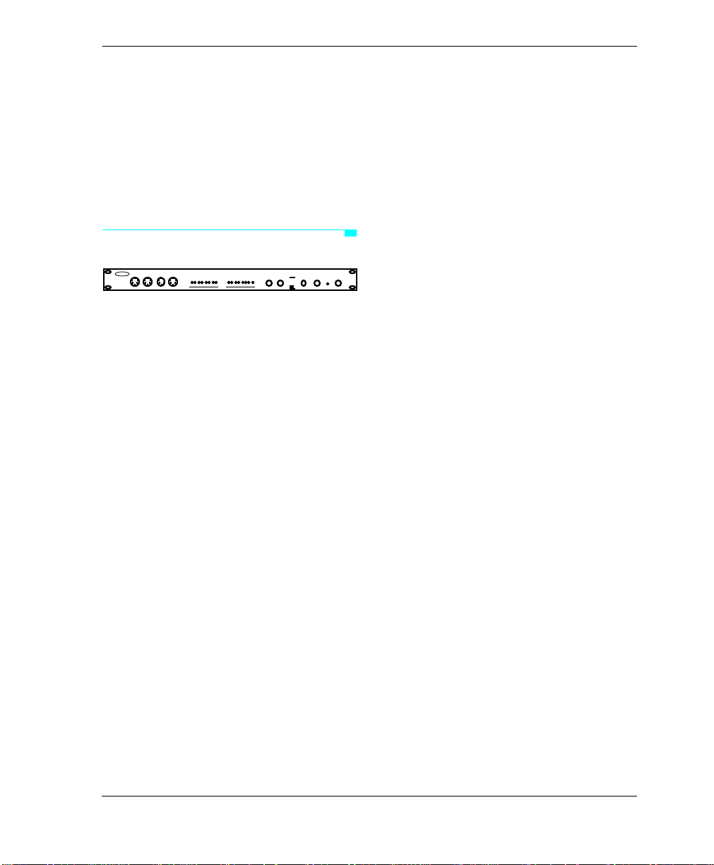
THE STUDIO 4 FRONT PANEL
OPCODE
A-THRU B-THRU
A-THRU B-THRU
OPCODE
SYSTEMS INC
SYSTEMS INC
POWERIN OUT IN OUT
POWERIN OUT IN OUT
7158
OMS
7158
OMS
16
16
Studio
Studio
IN
IN
23 645178
23 645178
14109 111213 1516
14109 111213 1516
4
4
OUT
OUT
23 645178
23 645178
14109 11 1 213 151 6
14109 11 1 213 151 6
1Mhz MIDI MIDI
1-8
1Mhz MIDI MIDI
1-8
FAST
9-16
FAST
9-16
Figure 2.1: Studio 4 Front Panel
From left to right, the front panel ports,
LED’s and buttons are as follows:
MIDI Ports 7/15 and 8/16
These two pairs of MIDI ports are on the
front panel to facilitate quick, temporary
connection of synthesizers, controllers or
other MIDI devices. MIDI ports are discussed in detail in “The Studio 4 Rear
Panel” section later in this chapter.
Front panel MIDI output ports 7/15 and
8/16 are duplicates of MIDI output ports
7/15 and 8/16 found on the rear panel. If
you connect a device to both a front panel
MIDI output and its corresponding rear
panel output, MIDI data will be sent to
both devices.
Front panel MIDI input ports 7/15 and 8/
16 are in addition to the 6 MIDI inputs
found on the rear panel. MIDI input ports
7/15 and 8/16 are not duplicated on the
rear panel.
If the 1-8/9-16 switch is in the 1-8 position,
these two ports are numbered 7 and 8. If
the 1-8/9-16 switch is in the 9-16 position,
the ports are numbered 15 and 16.
MIDI In LED’s
These eight red Light Emitting Diodes
(LED’s) indicate MIDI data is arriving at
one or more of the Studio 4’s eight MIDI
input ports.
MIDI Out LED’s
This row of green Light Emitting Diodes
(LED’s) indicates MIDI data is leaving
one or more of the Studio 4’s eight MIDI
output ports.
1MHz/Fast Switch
Use this switch to select a communication
speed. 1MHz is the standard MIDI interface speed required by most MIDI
software. Fast speed increases MIDI
throughput, thereby increasing the
number of simultaneous MIDI channels.
Check your MIDI application manuals to
see if they support Fast mode. Opcode
products that support Fast mode include
Vision, Studio Vision and EZ Vision.
Studio 4 Manual 7
Page 16
PART 1: Overview and Installation
NOTE:
The Studio 4 driver software must
match the speed selected by the 1MHz/Fast
switch. Configure the Studio 4 driver software as discussed in the “Studio 4<>Macintosh Communication Speed” section in Chapter 5.
1-8/9-16 Switch
Select the 1-8 position (switch in) if the
Studio 4 is the first or only Studio 4 in a
network. This assigns port numbers 1
through 8 to the Studio 4's eight MIDI
ports.
Select the 9-16 position (switch out) if the
Studio 4 is the second in a network. This
assigns port numbers 9 through 16 to the
Studio 4's eight MIDI ports. Network connections are discussed in Chapter 3.
NOTE:
If you are using just one Studio 4,
set this switch to the 1-8 position.
Thru Switches (A & B)
These switches provide convenient
access to printers, modems or other
peripherals.
position when your Macintosh needs to
communicate with an external peripheral
(such as a printer or modem).
SMPTE/Power Indicator Light
This LED blinks when there is any
SMPTE activity. When no timecode is
sent or received, the LED is lit as a power
indicator.
Power Switch
When pushed in, the power is ON. When
out, the power is OFF. The SMPTE/
Power LED should light when the switch
is in the ON position if the power supply is
connected to the Studio 4 and plugged in.
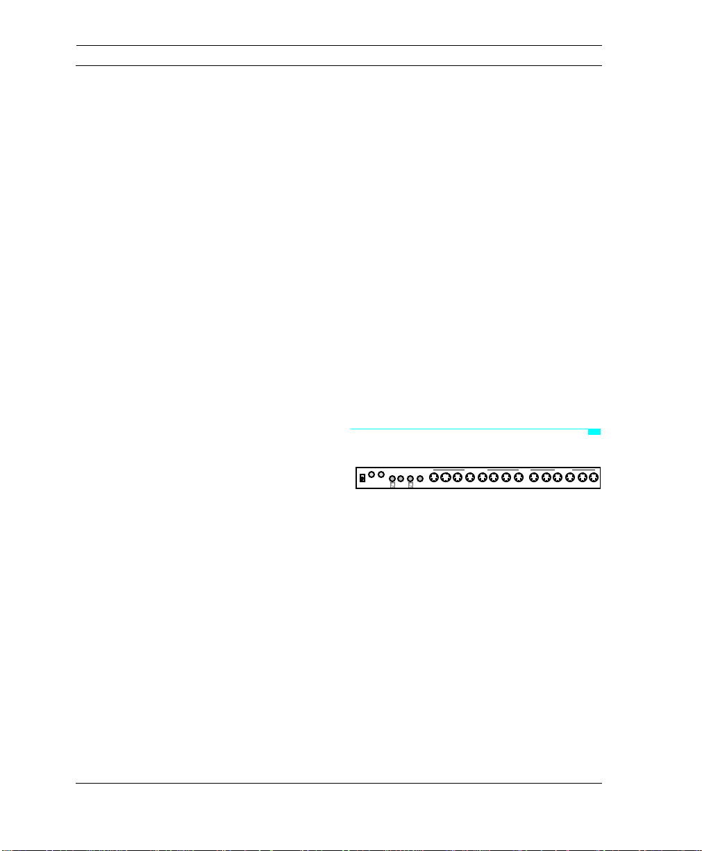
THE STUDIO 4 REAR PANEL
PORT B PORT A
OUT
IN
9VDC 816715614513412311210196145134123112101
B
THRUATHRU
Figure 2.2: Studio 4 Rear Panel
From left to right, the rear panel connectors are as follows:
MIDI OUT MIDI IN
9
When a Thru switch is in the MIDI position, the Studio 4 is in MIDI mode—
transmitting MIDI data between your
Macintosh and various studio devices.
When a Thru switch is in the THRU position, data from the Macintosh (as
Power Connector
Plug the power supply into this jack. Use
only a 9VDC 1.5A center-positive power
supply. The power supply is included with
the Studio 4.
received on either the “A” or “B” input
ports) is passed through the Studio 4 to
the “A Thru” or “B Thru” ports on the rear
panel. Set a Thru switch to the THRU
8 Opcode Systems, Inc.
Page 17

CHAPTER 2: Panel Descriptions
SMPTE IN Jack
This jack receives SMPTE timecode from
a tape deck or other SMPTE source. The
Studio 4 converts the SMPTE input into
the MIDI format specified by the Stripe
SMPTE window (see Chapter 10).
SMPTE OUT Jack
This jack outputs SMPTE timecode generated (or regenerated) by the Studio 4.
This jack is normally connected to the line
input of a tape deck. You may set the
SMPTE output level in the Stripe SMPTE
window (See Chapter 10).
Computer Ports and Thru Ports
The Studio 4 does not implement the traditional Macintosh MIDI interface
concept of a “Printer port” and a “Modem
port”. Older interfaces have a limit of 32
addressable MIDI channels; 16 on the
Printer port and 16 on the Modem port.
Each Studio 4, however, can address up to
128 separate MIDI channels spread
across its two serial inputs. These input
ports are labeled “A” and “B”. The inputs
(with the little Macintosh icons) connect
to the Macintosh using standard 8-pin
mini-DIN cables (supplied by Opcode
with the Studio 4).
You may connect the Studio 4 “A” port to
either the Macintosh Modem port or
Printer port. You may connect the
Studio 4 “B” port to the Modem port, the
Printer port or to another Studio 4 to form
a network. You can also connect two Macintosh computers to one or two Studio 4’s
(See “Computer Connections” in
Chapter 3).
You cannot use the “A” port for networking. As a matter of convention, you may
wish to connect “A” to the Modem port,
leaving the “B” port free for connecting
the Macintosh’s Printer port, another
Macintosh or another Studio 4.
Attach external peripherals (such as a
printer or modem) to the “A THRU” and/
or “B THRU” ports on the Studio 4. You
can use these peripherals without disconnecting the Studio 4 from the Macintosh.
Simply use the corresponding front panel
Thru switch to route data arriving at one
of the Studio 4 computer ports to its corresponding THRU port (see “Thru
Switches” earlier in this chapter, and
“Computer Connections” in Chapter 3).
MIDI OUT Connectors
Connect these eight ports to the MIDI IN
ports of your MIDI devices. Each port has
dual numbers that correspond to the position of the 1-8/9-16 switch on the front
panel.
MIDI output ports 7/15 and 8/16 are
duplicated on the front panel. If you connect devices to both a front panel MIDI
output and its corresponding rear panel
output, MIDI data is sent to both devices.
MIDI IN Connectors
Connect these six ports to the MIDI OUT
ports of your MIDI devices. Each port has
dual numbers that correspond to the posi-
Studio 4 Manual 9
Page 18

PART 1: Overview and Installation
tion of the 1-8/9-16 switch on the front
panel. Two additional inputs are on the
front panel.
ABOUT THE INTERFACE CABLES
The Studio 4 comes with standard 8-pin
mini-DIN cables. If you are using cables
other than the ones supplied with the
Studio 4, please ensure that they are 8-pin
mini-DIN.
You should use only high quality shielded
MIDI and audio cables when operating
your Studio 4 or any other professional
audio equipment.
10 Opcode Systems, Inc.
Page 19
CHAPTER 3: Hardware Installation
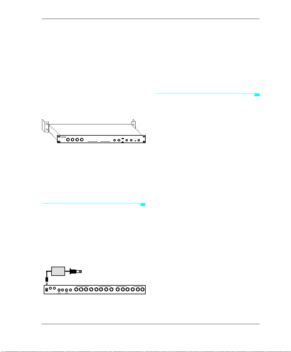
Use the rackmount screws (provided) to
mount the Studio 4 in a standard 19”
equipment rack as shown in Figure 3.1.
7158
OMS
OMS
IN OUT IN OUT
IN OUT IN OUT
7158
16
16
Studio
Studio
IN
IN
23 645178
23 645178
14109 111213 1516
14109 111213 1516
4
4
OUT
OUT
23 645178
23 645178
14109 111213 1516
14109 111213 1516
1Mhz MIDI MIDI
1Mhz MIDI MIDI
FAST
FAST
OPCODE
OPCODE
1-8
1-8
SYSTEMS INC
SYSTEMS INC
A-THRU B-THRU
9-16
A-THRU B-THRU
9-16
POWER
POWER
Figure 3.1: Rack Installation
If you do not wish to rack mount the
Studio 4, you may sit it on a steady surface. Attach the four rubber feet
(provided in this package) to the bottom
of the unit to prevent it from sliding.
POWER CONNECTION
Place the tip of the power supply cord into
the power jack on the far left side of the
rear panel, then plug the power supply
into a standard 120VAC, 60Hz electrical
outlet. Use only a 9VDC, 1.5A, center positive AC power adaptor with the Studio 4.
To
120VAC,
60Hz outlet
SMPTE
PORT B PORT A
IN
OUT
9VDC 816715614513412311210196145134123112101
B
THRUATHRU
Figure 3.2: Power Supply Connection
MIDI OUT MIDI IN
COMPUTER CONNECTIONS—
ONE STUDIO 4
You may connect the Studio 4 to either
the Macintosh’s Modem port, Printer
port, or to both. Connect the supplied
serial cables between the Studio 4 and the
Macintosh as discussed in the following
sections.
Single Port Connection
Single port connections are useful if you
frequently use a Macintosh serial port for
non-MIDI purposes (such as printing)
while running MIDI applications. You can
use the spare Macintosh serial port without using the Studio 4’s front panel MIDI/
THRU switch.
You may connect either the Studio 4’s “A”
port or “B” port to either the Macintosh
Modem or Printer port. The “B” port,
unlike the “A” port, can also be used to
connect an additional MIDI Interface. For
this reason (and as a matter of convention) you may with to connect “A” to the
Mac’s Modem port, leaving the “B” port
free for later connection to either the
Mac’s Printer port (discussed in the “Dual
9
Port Connection section”) or to another
interface (discussed in the “Computer
Connections—Networking” section).
Studio 4 Manual 11
Page 20
PART 1: Overview and Installation
s
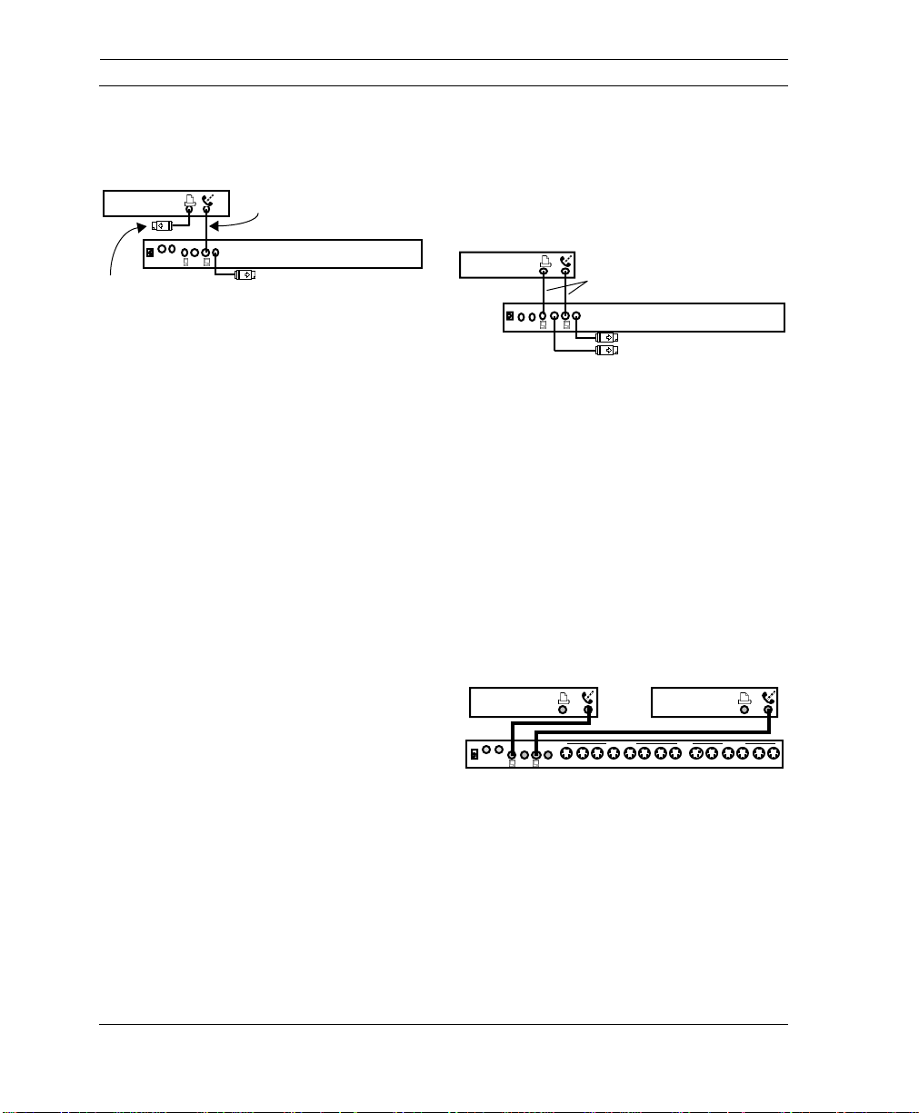
Figure 3.3 illustrates a common single
port connection.
PORT B PORT A
B
THRUATHRU
8-pin mini-DIN cable
(supplied)
Studio 4
Optional cable to peripheral
MACINTOSH
SMPTE
IN
OUT
9VDC
Optional cable
to peripheral
Figure 3.3: Single (Modem) Port Connection
Figure 3.3 uses only the Macintosh
Modem port for communicating with the
Studio 4. One external peripheral (such as
a printer) can be connected directly to the
Macintosh Printer port. You can connect
an additional external peripheral (such as
a modem) to the “A THRU” jack on the
Studio 4 and switch it in or out from the
front panel.
Dual Port Connection
Use a dual port connection if you need
increased MIDI “throughput” (for example, your MIDI data is densely packed
with notes, continuous controls, System
Exclusive messages and MIDI Time
Code). It’s a good idea to always use a
dual port connection when you’re synchronizing MIDI playback with SMPTE
timecode.
You may connect the Studio 4’s “A” port
to either Macintosh serial port. Similarly,
you may connect the “B” port to either the
Modem or Printer port.
Figure 3.4 illustrates a common dual port
connection. Connect both Macintosh
serial ports to the Studio 4, and attach any
external peripherals to the Studio 4 THRU
jacks. You can switch between the
Studio 4 and the external peripherals by
using the corresponding THRU switch on
the front panel.
MACINTOSH
SMPTE
IN
OUT
9VDC
Figure 3.4: Dual Port Connection
NOTE:
In a two cable system, such as
8-pin mini-DIN cables
(supplied)
PORT A
PORT B
B
THRUATHRU
Studio 4
Optional cables to peripheral
shown in Figure 3.4, use the Network Routing window to distribute data between ports
(see Chapter 6).
Connecting Two Macintosh Computers
Two Macintosh computers may share one
Studio 4 by connecting one Macintosh to
the Studio 4 “A” port and connecting the
other Macintosh to the Studio 4 “B” port.
MACINTOSH MACINTOSH
PORT B PORT A
OUT
IN
9VDC 816715614513412311210196145134123112101
B
THRUATHRU
Figure 3.5: Two Macs Sharing One Studio 4
You can also connect two Studio 4’s to two
Macintosh computers as shown in
Figure 3.6. This is an example of a
Studio 4 network. Networking connections are discussed in the next section.
MIDI OUT MIDI IN
9
12 Opcode Systems, Inc.
Page 21
MACINTOSH MACINTOSH
SMPTE
PORT B PORT A
OUT
IN
B
9VDC 816715614513412311210196145134123112101
THRUATHRU
PORT B PORT A
IN
OUT
B
9VDC 816715614513412311210196145134123112101
THRUATHRU
Figure 3.6: Two Macs Sharing Two Studio 4’s
MIDI OUT MIDI IN
MIDI OUT MIDI INSMPTE
If you connect two computers to a
Studio 4, you must check the
Computers
option in the
Multiple
Studio 4
menu. Do not check this option if you're
not using two computers to control the
Studio 4.
Multiple Macintosh Caveat
Use only one computer at a time to initiate
actions that change a Studio 4’s internal
state—always wait at least 1 second
before initiating any state-changing
actions from a different computer.
CHAPTER 3: Hardware Installation
the enabling and/or routing of Studio 4
inputs to the Macintosh computers may
be incorrect. If you suspect trouble,
choose
any OMS application and click OK.
9
9
OMS MIDI Setup
from within
COMPUTER CONNECTIONS— NETWORKING
A network is defined as the connection of
one or two Studio 4's to a single Macintosh serial port. The Macintosh has two
serial ports, so it can support two networks. Since each network can contain
either one or two Studio 4's, you can connect up to four Studio 4’s to a single
Macintosh for a maximum total of 512
MIDI channels.
NOTE
: When networking two Studio 4's,
always connect their “B” ports together.
Actions that cause the Studio 4 to change
state include:
• Clicking anywhere in either the Network Routing window or the Routing,
Channelizing and Muting window.
• Switching, opening or quitting
applications.
• Performing Galaxy patch transfers.
• Making different windows active in
Connecting Two Studio 4's to a
Macintosh
There are many possible ways to connect
two Studio 4's to a single Macintosh. You
can connect them as one network on a
single port, as two separate networks, or
as a 2-cable network. With two Studio 4’s,
you can access up to 256 independent
MIDI channels.
OMS Setup and the Studio Patches
Editor.
• Using the Enable Inputs dialog in
Vision.
If you use different computers to change
the Studio 4’s internal state too quickly,
Studio 4 Manual 13
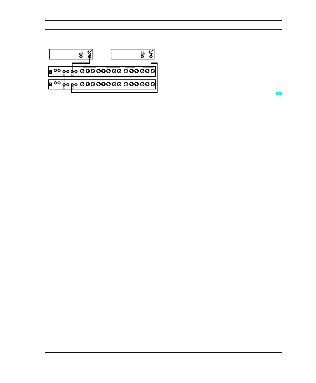
One Network/1-Cable
The first option is to connect both
Studio 4's in a single network as shown in
Figure 3.7. Set each Studio 4’s front panel
1-8/9-16 switch as indicated. You may
connect the network to either Macintosh
Page 22

PART 1: Overview and Installation
serial port. The advantage of this connection is that you retain a free Macintosh
serial port. The disadvantage is that all
MIDI and timecode communications
occur over a single Macintosh port—you
could get data overloads if you have a very
dense MIDI data stream and are syncing
to SMPTE timecode.
MACINTOSH
SMPTE
PORT B PORT A
IN
OUT
9VDC 816715614513412311210196145134123112101
B
THRUATHRU
SMPTE
PORT B PORT A
IN
OUT
B
9VDC 816715614513412311210196145134123112101
THRUATHRU
MIDI OUT MIDI IN
MIDI OUT MIDI IN
Set to 1-8
Set to 9-16
Figure 3.7: One Network of Two Studio 4's
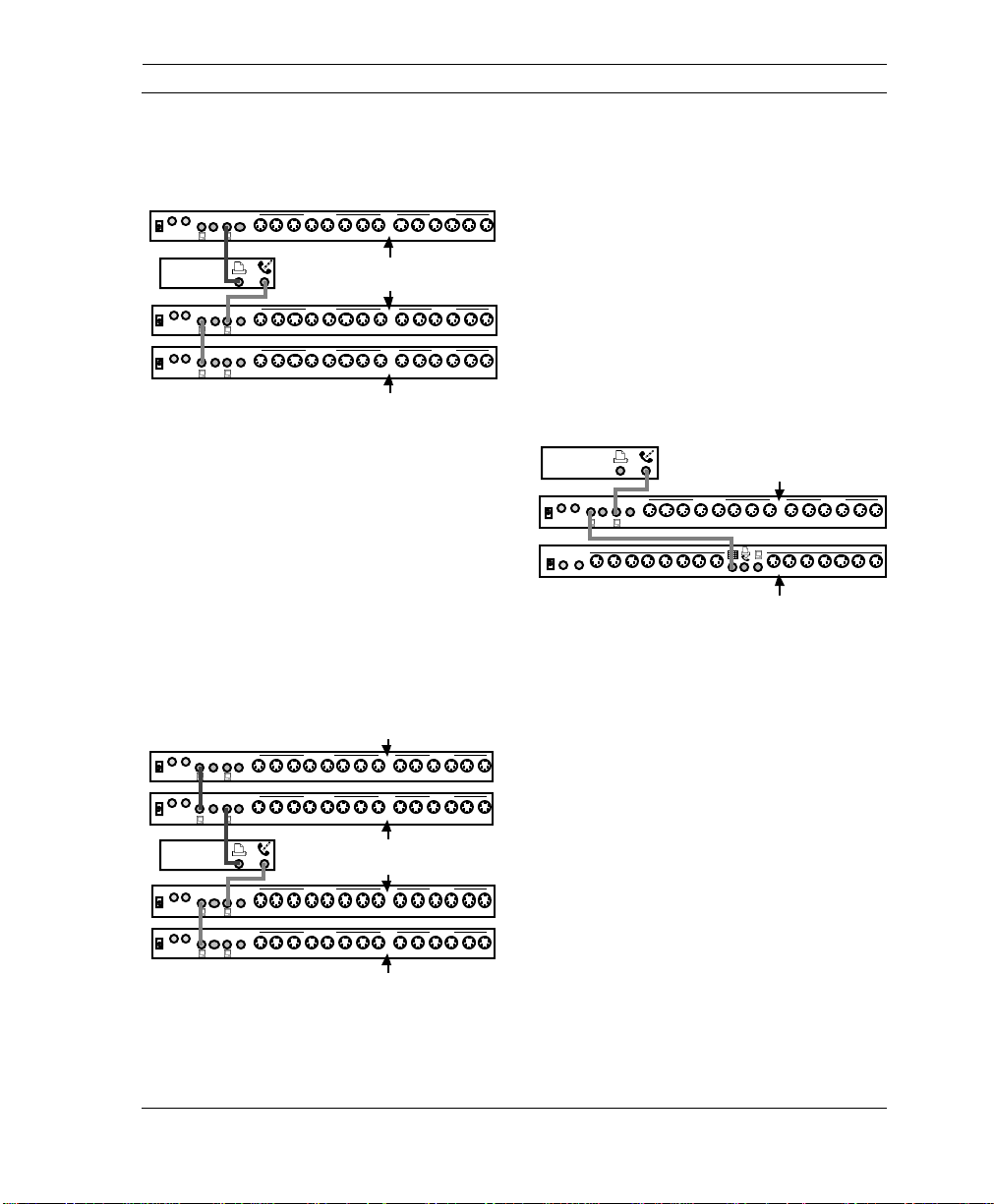
Two Networks
The second networking option involves
placing one Studio 4 on each Macintosh
serial port as shown in Figure 3.8. Set
each Studio 4’s front panel 1-8/9-16 switch
as indicated. With this connection, you
can balance the MIDI data stream
between the two Macintosh serial ports
using the Network Routing window (discussed in Chapter 6). You cannot,
however, use internal routings to send
MIDI data from one box to another (as
discussed in Chapter 7).
One Network/2-Cables
The final option is to use a single 2-cable
network. This is similar to the one network/1-cable configuration, except you
connect a second cable between the last
Studio 4's “A” port and the unused Macintosh serial port as shown in Figure 3.9.
Set each Studio 4’s front panel 1-8/9-16
switch as indicated.
This configuration provides optimum flexibility. You can balance the MIDI data
9
stream (unlike the one network/1-cable
connection) and you can use the
9
Studio 4's internal routing to send MIDI
data between interfaces (unlike the two
network connection). Use the Studio 4's
front panel THRU switches to access
external peripherals.
MACINTOSH
PORT B PORT A
OUT
IN
B
9VDC 816715614513412311210196145134123112101
THRUATHRU
SMPTE
PORT B PORT A
IN
OUT
9VDC 816715614513412311210196145134123112101
B
THRUATHRU
MIDI OUT MIDI IN
MIDI OUT MIDI IN
Figure 3.9: One 2-Cable Network of Two Studio 4's
Connecting Three Studio 4's to a
Macintosh
Set to 1-8
Set to 9-16
9
9
PORT B PORT A
IN
OUT
9VDC 816715614513412311210196145134123112101
B
THRUATHRU
MACINTOSH
PORT B PORT A
OUT
IN
9VDC 816715614513412311210196145134123112101
B
THRUATHRU
Figure 3.8: Two Networks of One Studio 4 Each
MIDI OUT MIDI IN
Set to 1-8
MIDI OUT MIDI IN
Set to 1-8
You must use two networks if you wish to
9
connect three Studio 4's to a Macintosh.
One network contains two Studio 4's; the
other network contains one. Set each
Studio 4’s front panel 1-8/9-16 switch as
indicated. Figure 3.10 shows a typical con-
9
nection involving three Studio 4's—with
14 Opcode Systems, Inc.
Page 23
CHAPTER 3: Hardware Installation
this connection, you can access up to 384
independent MIDI channels.
PORT B PORT A
IN
OUT
9VDC 816715614513412311210196145134123112101
B
THRUATHRU
MACINTOSH
PORT B PORT A
IN
OUT
9VDC 816715614513412311210196145134123112101
B
THRUATHRU
SMPTE
PORT B PORT A
IN
OUT
B
9VDC 816715614513412311210196145134123112101
THRUATHRU
Figure 3.10: Three Studio 4's in Two Networks
MIDI OUT MIDI INSMPTE
Set to 1-8
MIDI OUT MIDI INSMPTE
MIDI OUT MIDI IN
Set to 1-8
Set to 9-16
Connecting Four Studio 4's to a
Macintosh
You can connect a maximum of four
Studio 4’s to a Macintosh. This connection uses two networks of two Studio 4’s
as shown in Figure 3.11. Set each
Studio 4’s front panel 1-8/9-16 switch as
indicated. You can access up to 512 independent MIDI channels when you use
four Studio 4’s.
PORT B PORT A
IN
OUT
9VDC 816715614513412311210196145134123112101
9VDC 816715614513412311210196145134123112101
B
THRUATHRU
PORT B PORT A
OUT
IN
B
THRUATHRU
MACINTOSH
SMPTE
PORT B PORT A
IN
OUT
B
9VDC 816715614513412311210196145134123112101
THRUATHRU
PORT B PORT A
IN
OUT
9VDC 816715614513412311210196145134123112101
B
THRUATHRU
MIDI OUT MIDI INSMPTE
MIDI OUT MIDI INSMPTE
MIDI OUT MIDI IN
MIDI OUT MIDI INSMPTE
Figure 3.11: Four Studio 4's in Two Networks
Set to 9-16
Set to 1-8
Set to 1-8
Set to 9-16
Networking Studio 4's and MIDI
Time Pieces
You can use MIDI Time Pieces and
Studio 4’s together. In fact, the Studio 4
9
and MIDI Time Piece are completely
interchangeable in a 2-unit network.
When networked, OMS views the MIDI
Time Piece as another Studio 4 and uses
9
the Studio 4 OMS driver instead of the
MTP driver. Figure 3.12 illustrates an
9
example of a MIDI Time Piece in a
Studio 4 network.
MACINTOSH
PORT B PORT A
IN
OUT
B
9VDC 816715614513412311210196145134123112101
THRUATHRU
AUDIOINAUDIO
OUT
8167156145134123112101
Figure 3.12: MTP in a Studio 4 Network
NOTE: The MIDI Time Piece Network
port is equivalent to the Studio 4 “B” port.
Whenever you network a MIDI Time
Piece with a Studio 4, the MTP always
appears to OMS as a Studio 4. The MIDI
9
Time Piece OMS driver is used only when
the MIDI Time Piece is alone on a single
9
port or when it's networked with another
MIDI Time Piece.
NOTE: The Studio 4 uses a more efficient
9
communication protocol than the MIDI
Time Piece, so when networking these two
9
interfaces, it is best to have the Studio 4
connected to the Macintosh.
MIDI OUT MIDI INSMPTE
MIDI OUT MIDI IN
7
9
15
Studio 4 set to 1-8
6145134123112101
MTP set to 9-16
9
9
Studio 4 Manual 15
Page 24
PART 1: Overview and Installation
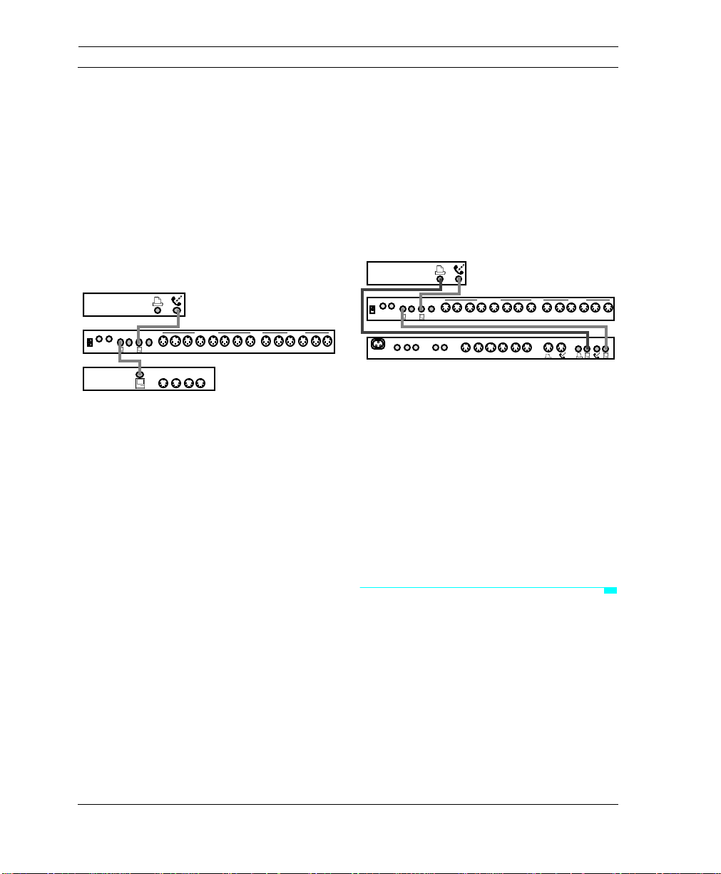
Networking Studio 4’s and
Standard MIDI Interfaces
You may network a Studio 4 with a standard MIDI interface. If you own an old
standard MIDI interface and have more
than 8 MIDI devices, the standard MIDI
interface will provide a few additional
MIDI ports. Figure 3.13 shows an example of a Studio 4 networked with a
standard MIDI interface.
MACINTOSH
SMPTE
PORT B PORT A
OUT
IN
9VDC 816715614513412311210196145134123112101
B
THRUATHRU
STANDARD
MIDI
INTERFACE
Figure 3.13: Standard MIDI Interface in a Studio 4
Network
Because your Studio 4 must be used at
1MHz when networked with a standard
MIDI interface and because MIDI routing
is not as flexible as with a network of two
Studio 4’s, you should consider this
arrangement only as a temporary “band
aid”. If you often need to access more
than 8 MIDI devices, you should seriously consider purchasing an additional
Studio 4.
NOTE: You cannot network a self-powered
standard interface (such as a MIDI Translator) with the Studio 4.
If you use a dual port standard MIDI interface, you can connect its second serial
port to the free Macintosh serial port to
access even more MIDI ports.
MIDI OUT MIDI IN
MIDI
MIDI
MIDI
MIDI
OUT
OUT
IN
OUT
If your dual port standard MIDI interface
is a Studio 3, Opcode strongly recommends that you connect the Studio 3
modem port to the Studio 4 “B” port, and
the Studio 3 printer port directly to the
Macintosh (as shown in Figure 3.14).
This is because the Studio 3 communicates with the Macintosh only over its
printer port.
MACINTOSH
SMPTE
PORT B PORT A
OUT
IN
9VDC 816715614513412311210196145134123112101
B
THRUATHRU
FOOTSWITCHES
9
TAPE / AUDIO
FS2 FS1 FC1 OUT IN
MIDI OUT MIDI IN
MIDI OUT MIDI IN
123456
Figure 3.14: Studio 3 in a Studio 4 Network
Network connections involving a Studio 4
and a standard MIDI interface are rather
atypical. If you use this type of network in
your studio, you should first learn to use
the Studio 4 by itself. Only after you
understand the operations of the Studio 4
and OMS patches should you attempt this
network. For this reason, instructions for
working with these connections are discussed in Appendix B.
SMPTE CONNECTIONS
The Studio 4 has two SMPTE jacks on its
rear panel. The SMPTE IN jack is used to
receive a tape sync signal. The SMPTE
OUT jack sends SMPTE timecode as
specified in the Stripe SMPTE window
discussed in Chapter 10. If the Studio 4 is
receiving SMPTE at its SMPTE IN jack, it
PRINTER
9
MODEM
PORT
PORT
16 Opcode Systems, Inc.
Page 25
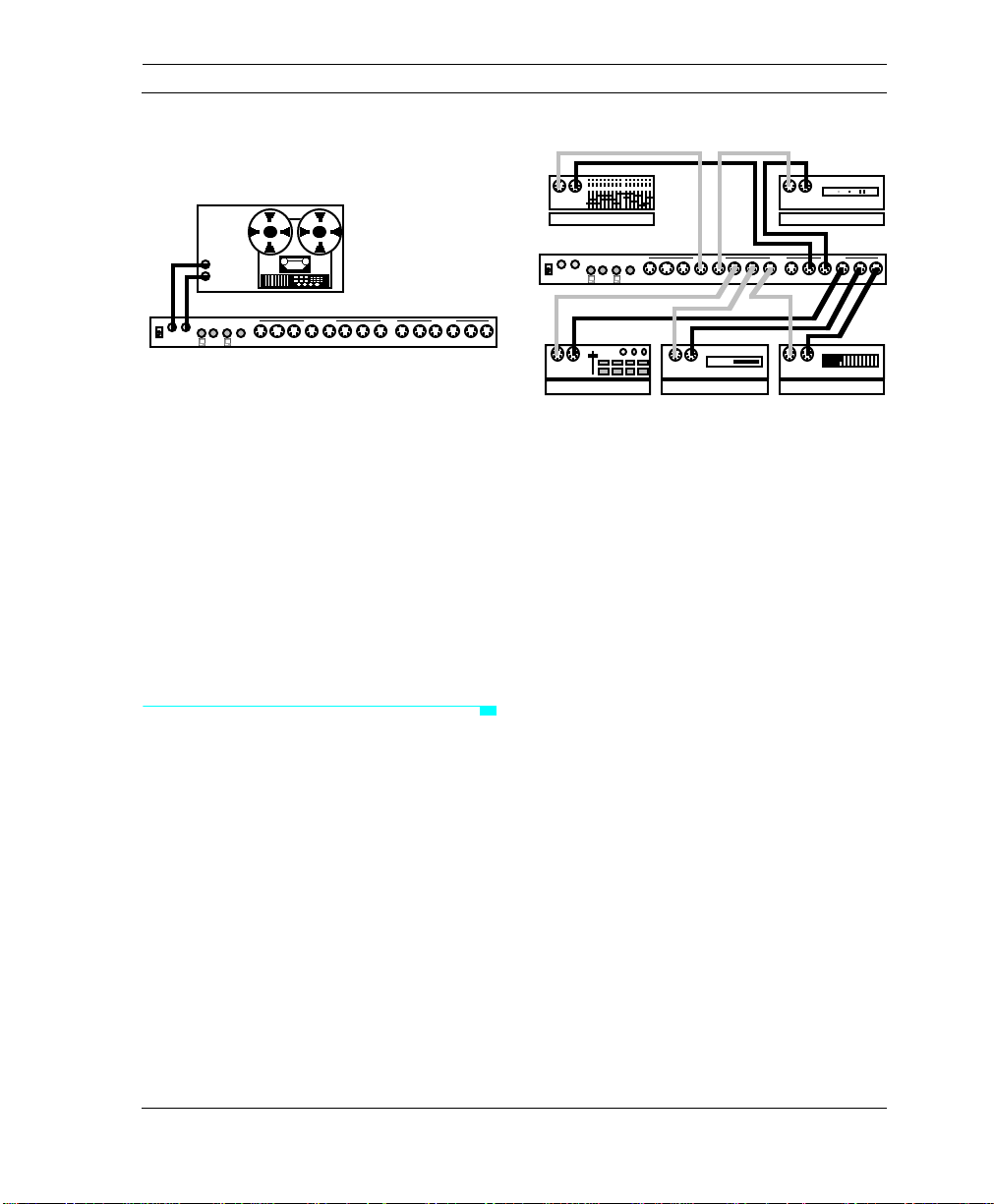
duplicates the timecode and sends it to
the SMPTE OUT jack.
IN OUT
CHAPTER 3: Hardware Installation
MIDI MIXER
IN OUT
MIDI EFFECTS
Audio Out
Audio In
PORT B PORT A
IN
OUT
9VDC 816715614513412311210196145134123112101
B
THRUATHRU
MIDI OUT MIDI INSMPTE
Figure 3.15: SMPTE Connections
To use the Studio 4 as a synchronization
device, connect a pair of shielded audio
cables between the Studio 4 and a multitrack tape deck. Connect the SMPTE
OUT jack to the audio input of a tape deck
for SMPTE striping (usually the last
track). Connect the SMPTE IN jack of the
Studio 4 to the audio output of the multitrack’s SMPTE track. Connect the
Studio 4 directly to the tape deck, bypassing the mixing console, equalizer, or any
other signal processing equipment.
MIDI CONNECTIONS
Connect a MIDI device’s MIDI input to a
MIDI OUT port on the Studio 4. Connect
the like-numbered Studio 4 MIDI IN port
to the device’s MIDI output. Figure 3.16
shows some typical MIDI connections.
SMPTE
PORT B PORT A
IN
OUT
9VDC 816715614513412311210196145134123112101
B
THRUATHRU
9
IN OUT
DRUM MACHINE
MIDI OUT MIDI IN
IN OUT
SYNTH MODULE
Figure 3.16: MIDI Connections
NOTE: If you wish to load patches from a
device into Opcode’s Galaxy program, you
must connect that device’s MIDI In and
Out ports to identically-numbered ports on
the Studio 4 (as shown in Figure 3.16).
9
IN OUT
SYNTHESIZER
Studio 4 Manual 17
Page 26

PART 1: Overview and Installation
18 Opcode Systems, Inc.
Page 27

CHAPTER 4: Software Installation and Setup
INSTALLING OMS AND THE
STUDIO 4 SOFTWARE
NOTE: If you have never used OMS, you
should stop and read the OMS manual
before continuing with the Studio 4
manual.
The Studio 4 uses the OMS Setup and
Studio Patches Editor applications with
the Studio 4 OMS driver to control all
mapping, channelizing routing and timecode functions.
Follow the installation instructions on the
OMS disk to install OMS and the Studio 4
software.
What's Installed
The Installer places all the necessary
OMS and Studio 4 files onto your hard
disk automatically. After running the
Installer and restarting your Macintosh,
you can begin to use OMS and your
Studio 4.
NOTE: You must install the Studio 4 OMS
driver to use the Studio 4. The Studio 4
requires OMS version 1.2 or later.
See the OMS manual to learn about the
various OMS files and where they’re
installed.
The Studio 4 package includes some additional files that aren’t part of basic OMS:
• Studio Patches Editor —This appli-
cation adds the ability to create OMS
patches. OMS patches are discussed
in Part Three of this manual.
• OMS Program Changes—This
driver allows you to change OMS
patches from Macintosh applications
and is installed in the OMS Folder
within the System Folder. See
“Sequencing Patch Changes” in
Chapter 11 for more information.
• Studio 4 OMS Driver—This driver
allows OMS to operate with your
Studio 4 and is installed in the OMS
Folder within the System Folder.
CAUTION: Do not relocate or rename any
files or folders that the Installer places in
the System Folder. You may delete unnecessary files, but some files are essential for
OMS operation. See the Software Definitions section of your OMS manual for more
information.
Although the Studio 4 works with nonOMS applications, all programming and
setup of the Studio 4 is handled by OMS.
Studio 4 Manual 19
Page 28
PART 1: Overview and Installation
If you have never worked with OMS,
please read the OMS manual before continuing with the Studio 4 manual.
LAUNCHING THE OMS SETUP APPLICATION
By now you should have connected the
Studio 4 to your Macintosh and installed
the OMS software. The next step is to
launch the OMS Setup application:
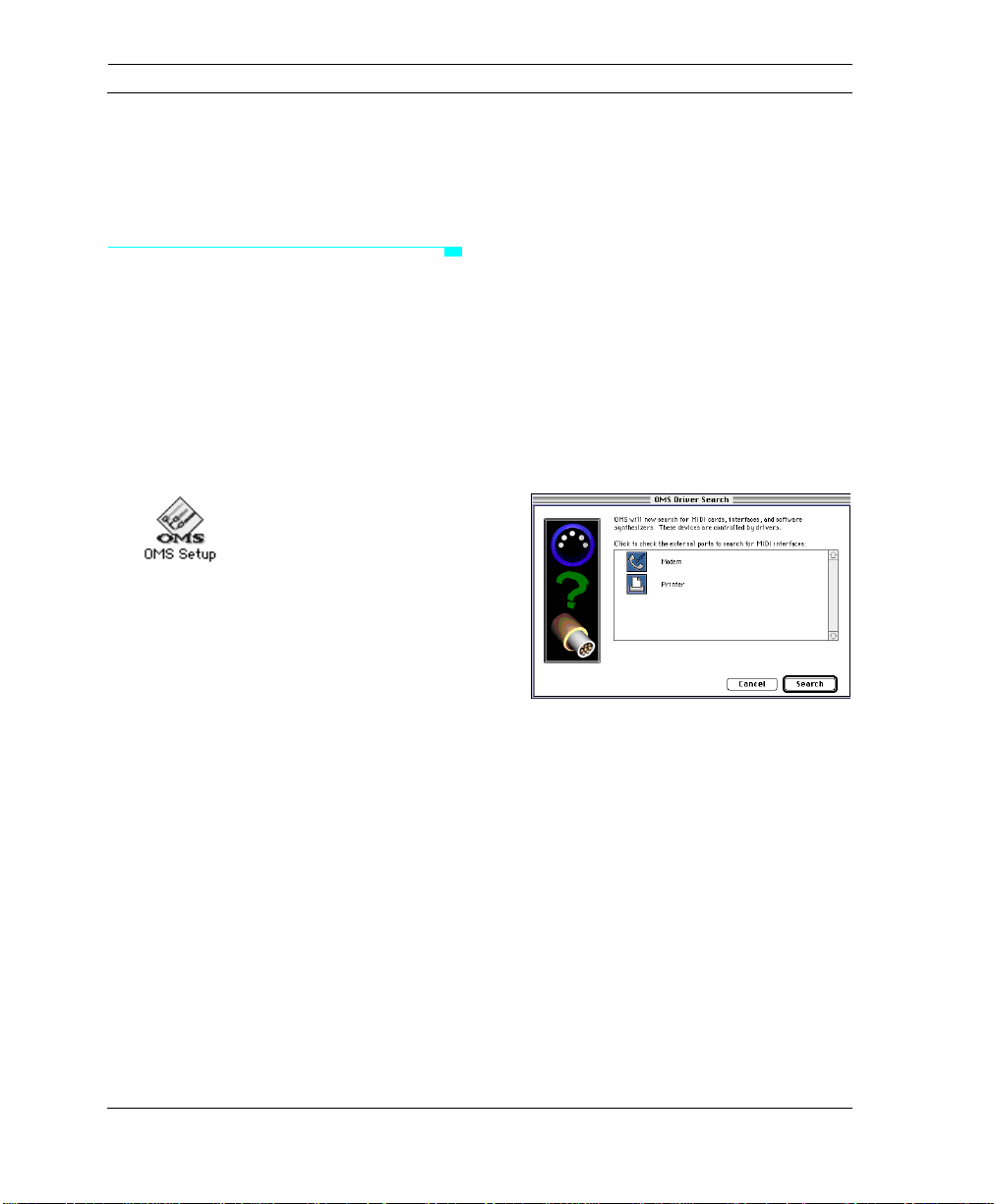
햲 Turn on your Studio 4.
햳 Double-click the OMS Setup icon.
If you have never used OMS, or if you
haven't defined a current Studio Setup
document, you will need to open and
create a new Studio Setup document.
Your OMS manual describes this procedure in detail, but highlights are included
in the next section, “Creating a New
Custom Studio Setup Document.”
If you are already an OMS user and have
defined a current Studio Setup document,
you will need to update your setup to
work with the Studio 4. This is described
in “Updating an Old Studio Setup Document”, later in this chapter.
Creating a New Custom Studio Setup Document
햲 Launch the OMS Setup application.
If you do not have a current OMS Studio
Setup document, you will be asked to
create one when you launch the OMS
Setup application.
A dialog box appears (as shown in
Figure 4.1). There is a check box for
each Macintosh serial port. You should
check only those ports that are connected to the Studio 4 or any other MIDI
interface you wish to appear in your
Studio Setup document.
Figure 4.1: Interfaces Dialog Box
햳 Click Search or hit the return key.
The Macintosh searches the checked
serial ports for MIDI interfaces. It also
looks for any NuBus cards that have an
OMS driver installed. When it finds all
interfaces and cards, it creates a new,
untitled Studio Setup document. The
20 Opcode Systems, Inc.
Page 29

CHAPTER 4: Software Installation and Setup
Studio Setup document contains an icon
for each Studio 4 and OMS driver object
found.
Figure 4.2: Untitled Studio Setup Document
햴 Add MIDI devices and connect them
as discussed in your OMS manual.
Each device that you connect to the
Studio 4 will have a port number in its
path. You must set MIDI port numbers in
the Studio Setup document to reflect the
actual Studio 4 port numbers to which
devices are connected.
Updating an Old Studio Setup Document
햲 Launch OMS Setup.
Your current studio setup document
opens.
Figure 4.3: Standard Interface Studio Setup
Document
햳 Choose Studio>MIDI Cards &
Interfaces to open the Update Setup
dialog box.
Figure 4.4: Update Setup Dialog Box
If you already have a current Studio Setup
document, but it doesn’t reflect your current studio configuration (for example,
you had a standard interface, but are now
using the Studio 4), you’ll need to update
it.
Studio 4 Manual 21
햴 Click Update Setup or hit the return
key.
A dialog box appears. There is a check
box for each Macintosh serial port. You
should check only those ports that are
Page 30

PART 1: Overview and Installation
connected to the Studio 4 or any other
MIDI interface you wish to appear in your
Studio Setup document.
Figure 4.5: Interfaces Dialog Box
햵 Click Search or hit the return key.
Your old interface disappears from your
Studio Setup document and is replaced
with a Studio 4 icon. Any devices that
were attached to old interfaces appear
unconnected in the updated Studio
Setup document.
the Studio Setup document to reflect the
actual Studio 4 port numbers to which
devices are connected.
Figure 4.7: Updated Studio Setup Document
햷 Save your Studio Setup document.
STUDIO 4 ICONS IN A STUDIO
SETUP DOCUMENT
The Studio 4 icons that appear in your
Studio Setup document depend on the
number of Studio 4's and how they're connected to the Macintosh. Each Studio 4 is
given its own icon and shows the name of
the Macintosh serial port to which it’s
connected. If the words “2 cables” appear,
it indicates that two connecting cables are
used.
The following sections show specific
Figure 4.6: Unconnected Setup Document
examples of Macintosh-to-Studio 4 connections and the resulting Studio Setup
햶 Connect the device icons to the
Studio 4 icon using techniques
discussed in the OMS manual.
Each device that you connect to the
Studio 4 will have a port number in its
path. You must set MIDI port numbers in
22 Opcode Systems, Inc.
icons.
One Studio 4
If you have only one Studio 4 connected
to your Macintosh when you search the
Page 31

CHAPTER 4: Software Installation and Setup
serial ports, then your Studio Setup document will contain one Studio 4 icon.
Figure 4.8 shows the possible ways to
connect a single Studio 4 to a Macintosh
and the Studio Setup icons that result.
Mac <-> Studio 4 Connection Studio Setup Icon
Macintosh
PORT B PORT A
B
THRUATHRU
Macintosh
PORT B PORT A
B
THRUATHRU
Studio 4
Studio 4
Macintosh
PORT B PORT A
B
THRUATHRU
Macintosh
PORT B PORT A
B
THRUATHRU
Macintosh
PORT B PORT A
B
THRUATHRU
Macintosh
PORT B PORT A
B
THRUATHRU
Studio 4
Studio 4
Studio 4
Studio 4
Figure 4.8: Studio Setup Icons—One Studio 4
Notice that when both serial ports are
connected to a single Studio 4, there is
only one icon. When a standard MIDI
interface is connected to both serial ports
you see two icons; one representing the
Modem port and the other the Printer
port. The Studio 4 appears as a single
interface because you use the Network
Routing window (discussed in Chapter 6)
to allocate MIDI data to each of the serial
ports.
Two Studio 4's
There are numerous ways to connect two
Studio 4's to a Macintosh. Some of these
connections are shown in Figure 4.9
along with the resulting Studio Setup
icons.
Mac <-> Studio 4 Connection Studio Setup Icon
Macintosh
PORT B PORT A
Studio 4
B
THRUATHRU
PORT B PORT A
Studio 4
B
THRUATHRU
Macintosh
PORT B PORT A
Studio 4
B
THRUATHRU
PORT B PORT A
Studio 4
B
THRUATHRU
PORT B PORT A
Studio 4
B
THRUATHRU
Macintosh
PORT B PORT A
Studio 4
B
THRUATHRU
Figure 4.9: Studio Setup Icons—Two Studio 4's
The “1-8” and “9-16” next to the Studio 4
icons indicate the MIDI port numbers
when there are two Studio 4's in a network (as selected by the Studio 4’s front
panel 1-8/9-16 switch).
Studio 4 Manual 23
Page 32

PART 1: Overview and Installation
Three Studio 4's
Figure 4.10 illustrates some connections
involving three Studio 4's and the resulting Studio Setup icons.
Mac <-> Studio 4 Connection Studio Setup Icon
PORT B PORT A
Studio 4
B
THRUATHRU
Macintosh
PORT B PORT A
Studio 4
B
THRUATHRU
PORT B PORT A
Studio 4
B
THRUATHRU
PORT B PORT A
Studio 4
B
THRUATHRU
Macintosh
PORT B PORT A
Studio 4
B
THRUATHRU
PORT B PORT A
Studio 4
B
THRUATHRU
Figure 4.10: Studio Setup Icons—Three Studio 4's
Four Studio 4's
If you connect four Studio 4’s to a Macintosh, they will be shown in the Studio
Setup document as shown in Figure 4.11.
Mac <-> Studio 4 Connection Studio Setup Icon
PORT B PORT A
Studio 4
B
THRUATHRU
PORT B PORT A
Studio 4
B
THRUATHRU
Macintosh
PORT B PORT A
Studio 4
B
THRUATHRU
PORT B PORT A
Studio 4
B
THRUATHRU
Figure 4.11: Studio Setup Icons—Four Studio 4's
RENAMING STUDIO 4'S
You can rename one or more of your
Studio 4's in the Studio Setup document.
To do so, simply click the name to the
right of the Studio 4 icon and type in a
new name. The name you choose appears
in place of the default Studio 4 name anywhere that the interface name appears.
In the following example, Figure 4.12
shows a Studio Setup document with the
default Studio 4 name and a pop-up menu
listing the Studio 4 as a selection.
Figure 4.13 shows a Studio Setup document with a custom Studio 4 name and
the same pop-up menu listing the Studio 4
as a selection.
24 Opcode Systems, Inc.
Page 33

Figure 4.12: Default Studio 4 Name
Figure 4.13: Custom Studio 4 Name
CHAPTER 4: Software Installation and Setup
OTHER ICONS IN A STUDIO SETUP DOCUMENT
Your Studio Setup document also displays
icons for any other interfaces, NuBus
cards or devices connected directly to
your Macintosh.
A MIDI Time Piece always uses the
Studio 4 driver when it’s networked with a
Studio 4., It appears in the Studio Setup
document as a Studio 4 with the default
name “MTP as S4”. The only time a MIDI
Time Piece icon appears is when the MTP
is alone on its own port, or when it's networked with another MTP.
Interface icons and NuBus card icons are
discussed in your OMS manual.
Studio 4 Manual 25
Page 34

PART 1: Overview and Installation
26 Opcode Systems, Inc.
Page 35

PART 2: Using The Studio 4
Studio 4 Manual 27
Page 36

PART 2: Using The Studio 4
28 Opcode Systems, Inc.
Page 37

CHAPTER 5: Introduction
Before beginning this section, you should
have read your OMS manual and created
a current Studio Setup document.
Studio 4 programming uses OMS and references the current Studio Setup
document. If you haven't read your OMS
manual or if you haven't created a Studio
Setup document, do so at this time.
The Studio 4 integrates seamlessly with
programs that use OMS. With programs
that don't use OMS, it can emulate a
MIDI Time Piece or it can be used as a
standard MIDI interface.
There are three ways to control MIDI
routing when you use a Studio 4:
• With a sequencer application.
Most sequencers (such as Vision or
Performer) control MIDI routing
within the application. You use the
sequencer to route MIDI inputs to
MIDI outputs.
• With a Studio 4 state. A Studio 4
state reflects the settings of the Network Routing window (see Chapter
6) and the MIDI Routing, Channelizing and Muting window (see Chapter
7). You can save and recall Studio 4
states at any time. The Studio 4
always retains the latest state even
when power is turned off.
• With an OMS patch. OMS patches
allow you to design very advanced
MIDI routing and processing paths
using the Macintosh (not the
Studio 4) to process MIDI data. OMS
patches are discussed in the Studio
Patches Editor manual.
USING THE STUDIO 4 WITH
OMS-COMPATIBLE
APPLICATIONS
Unless you use the Studio 4 for strictly for
live performance, you'll probably use it
with sequencers, librarians and other
MIDI applications. These programs
require you to enable MIDI input devices
within them—that is, you need to tell the
application which MIDI device(s) you'll
use to input MIDI data.
With OMS-compatible applications (such
as Vision and Galaxy) you need only
make sure the input is enabled within the
application in order to route data from the
device, through the Studio 4 and into the
application. When you enable input
devices within OMS-compatible applications, OMS tells the Studio 4 driver which
inputs are enabled. The Studio 4 driver
then tells each Studio 4 in your network
which inputs to route to the Macintosh.
Studio 4 Manual 29
Page 38

PART 2: Using The Studio 4
In OMS-compatible applications, if you
choose the Studio 4 as a MIDI input, only
timecode from the Studio 4 and MIDI
beat clock from any devices connected to
the Studio 4 are sent to the application—
other types of MIDI data from devices
attached to the Studio 4 are not sent.
Select devices by name (rather than
selecting the interface) if you want to use
them as MIDI inputs.
For example, look at Figure 5.1.
1. In Vision, choosing
Enable Input Devices
opens this dialog box
2. Use this dialog box to tell Vision
which devices will send it data.
Figure 5.1: Enabling Inputs in Vision
In this example, the GeoSkin Drums,
Masterman 88 and MIDI Tuba are
enabled as input devices in Vision (they
are highlighted). Vision “sees” MIDI data
only from these devices. Data from other
devices connected to the Studio 4 is not
sent to Vision.
See your OMS-compatible application
manuals for more information.
USING THE STUDIO 4 WITH
NON-OMS APPLICATIONS
The Studio 4 acts like a standard interface
or a MIDI Time Piece when used with
non-OMS applications. Use the Network
Routing window’s Compatibility columns
to enable MIDI inputs and outputs, and
the Port columns to choose port assignments. The Network Routing window is
discussed in Chapter 6.
STUDIO 4<->MACINTOSH
COMMUNICATION SPEED
For each Studio 4 that's connected
directly to a Macintosh, you must set a
basic communication speed to match both
the position of the Studio 4’s front panel
1MHz/Fast switch and the communication speed settings you choose in your
MIDI applications. If you’re using Fast
mode, you may also optimize the
Studio 4-to-Macintosh communication
speed for maximum MIDI throughput.
To establish communication speed, you
must:
햲 Open the current OMS Studio Setup
document and double-click a Studio 4
icon to open the Studio 4<>Macintosh Communication Speed
dialog box.
30 Opcode Systems, Inc.
Page 39

CHAPTER 5: Introduction
햶 Click OK when youÕre finished and
perform the same operation for any
other Studio 4's connected directly to
the Macintosh.
Figure 5.2: Double-click Studio 4 Icon
The Studio 4<->Mac Communication
Speed dialog box looks as shown in
Figure 5.3.
Figure 5.3: Studio 4<->Mac Communication
Speed Dialog Box
햳 Set a basic communication speed
with the top set of radio buttons.
햴 Set a Studio 4->Macintosh
communication speed with the lower
set of radio buttons.
These buttons allow you, when in Fast
mode only, to select an optimum
Studio 4->Mac communication speed.
햵 On the Studio 4's front panel, set the
1MHz/Fast switch to match the setting
in the Communication Speed dialog
box.
Determining the Optimum
Studio 4->Mac Speed
The optimum Studio 4->Mac speed provides the fastest communication speed
without overrun errors. The default is
1.33 x MIDI. Increase this speed if you
would like higher throughput. Decrease it
if you get overrun errors.
THE STUDIO 4 MENU
A Studio 4 menu appears in the OMS
Setup application whenever a Studio 4
driver is installed and the current Studio
Setup document contains one or more
Studio 4’s. Studio 4 menu commands are
described in the indicated chapters.
Chapter 9
Chapter 10
Chapter 6
Chapter 7
Chapter 8
This Chapter
Chapter 3
This Chapter
Figure 5.4: Studio 4 Menu
Studio 4 Manual 31
Page 40

PART 2: Using The Studio 4
Display ROM Version...
Choose this command to display the version numbers of your Studio 4 ROM. You
should know your ROM version if you call
Opcode Technical Support about your
Studio 4.
Choosing Between Multiple
Studio 4’s
Any time the current Studio Setup document contains more than one Studio 4,
you’ll see a listing of them at the bottom of
the Studio 4 menu.
To select (check) a Studio 4, simply pull
down the menu and release the mouse
over the desired Studio 4.
The SMPTE Reader and Stripe SMPTE
windows work with the selected Studio 4.
You must select a Studio 4 before opening
either the SMPTE Reader or Stripe
SMPTE windows. The SMPTE Reader
window is discussed in Chapter 9. The
Stripe SMPTE window is discussed in
Chapter 10.
Using the Studio 4 Menu with a
MIDI Time Piece
If you network a MIDI Time Piece with a
Studio 4, the MTP appears as a Studio 4 in
the Studio Setup document and is labeled
“MTP as S4”. Everything in the Studio 4
menu works with the networked MTP
except Stripe SMPTE, Jam Sync and
Display ROM Version. You can open
the SMPTE Reader window for a MIDI
Time Piece that's networked to a Studio 4
and it’ll work except you can't change the
MIDI synchronization format.
Choose any Studio 4 on a modem port to
open either a Network Routing window or
a Routing, Channelizing and Muting
window for the modem port. Similarly,
choose any Studio 4 on a printer port to
open either a Network Routing window or
a Routing, Channelizing and Muting
window for the printer port. The Network
Routing window is discussed in
Chapter 6. The Routing, Channelizing and
Muting window is discussed in Chapter 7.
32 Opcode Systems, Inc.
Page 41

CHAPTER 6: Network Routing Window
WHEN TO USE THE NETWORK ROUTING WINDOW
You need to use the Network Routing
window when:
• working with non-OMS applications.
• using both Macintosh serial ports
(Printer and Modem) with one or
more Studio 4’s.
You will never need the Network Routing
window if you use only one Macintosh
serial port and you use only OMS MIDI
applications.
WINDOW OVERVIEW
Choose Network Routing from the
Studio 4 menu to open the Network
Routing window.
Figure 6.1: Network Routing Window
The Network Routing window displays
the names of the devices entered in your
current OMS Studio Setup document.
Click the Help button to open on-line
information about the Network Routing
window.
Studio 4 Manual 33
Page 42

PART 2: Using The Studio 4
The Network Routing window shown in
Figure 6.1 is based on the Studio Setup
document shown in Figure 6.2. Your Network Routing window will reflect your
own current OMS Studio Setup
document.
Figure 6.2: Studio Setup Document
The Network Routing window has two
functions:
• When working with non-OMS applications, it controls which inputs the
Studio 4 sends to the Macintosh and
which devices receive output from
the Macintosh.
• For any application, if you connected
both Macintosh ports to one or more
Studio 4’s, it controls which port carries the data for each device defined
in your current OMS Studio Setup
document.
Routing window (or you make another
window active). If you want your Studio 4
to remember the most recent Network
Routing configuration, turn it off only after
closing or de-activating this window.
Multiple Studio 4’s
If you have either one or two Studio 4’s in
a single network, you’ll have only one Network Routing window. That window’s title
bar indicates whether your network is
connected to the Modem port, the Printer
port, or both (2 cables).
If you have two Studio 4 networks (one
network connected to each Macintosh
serial port), you’ll have two Network Routing windows (one for each port). From
the Studio 4 menu, choose any Studio 4
on the modem port to open the Network
Routing window for the modem port.
Choose any Studio 4 on the printer port to
open the Network Routing window for the
printer port.
When you edit this window, the changes
are sent immediately to the Studio 4. The
Studio 4 always reflects the current setup
of this window. The Studio 4 remembers
this setup when you close the Network
34 Opcode Systems, Inc.
Page 43

CHAPTER 6: Network Routing Window
SETTING THE MIDI INPUTS
The left side of the Network Routing
window contains the MIDI In columns.
These columns control the signal routing
from each MIDI device to the Macintosh.
You can also route the timecode signal
generated by the Studio 4.
Figure 6.3: Network Routing Window’s MIDI Input
Side
MIDI In Port Column
Use the MIDI In Port column to balance
the MIDI input data between the two
Macintosh serial ports. For instance, timecode data is very dense—so to prevent
timing errors, you should always route
timecode to the least used serial port (ideally, its own port).
In Figure 6.3, data from the Masterman88, ProMaker/1 and Vectorific is sent to
the Macintosh Modem port. Timecode is
sent to the Macintosh Printer port.
If you connect only one Macintosh serial
port to a Studio 4 (or pair of Studio 4’s),
the Port column merely illustrates which
Macintosh port is used; you can’t change
the port assignment by clicking it.
TIMECODE NOTE: The Macintosh can
handle only one incoming timecode stream
per serial port. If you’re using multiple
Studio 4’s, it’s up to you to make sure that
no more than one Studio 4 per port is sending timing information to the Macintosh.
If you connect both Macintosh serial
ports to a network (consisting of either
one or two Studio 4’s), you can select
which serial port each device uses to communicate with the Macintosh. You can
switch between ports by clicking the port
icon in the Port column. Choose either
the Printer port or the Modem port for
each device. You can also choose to route
timecode (as generated by the Studio 4)
to either the Macintosh Printer or Modem
port. Click and drag down the Port
column to change many port assignments
quickly.
Studio 4 Manual 35
MIDI In Compatibility Column
Use the Compatibility (Compat) column
to enable device inputs when you work
with non-OMS software. Click each
device’s Compatibility column to toggle
between enabled (checked) and disabled
(unchecked). Click and drag down the
Compatibility column to change multiple
compatibility settings.
Page 44

PART 2: Using The Studio 4
In Figure 6.3, only timecode and MIDI
data from the Masterman-88 are sent to
non-OMS applications. MIDI data from
the ProMaker/1 and Vectorific sound
modules will not be sent to non-OMS
applications.
IMPORTANT: If you’re using non-OMS
MIDI applications, you MUST enable
devices in the MIDI In Compatibility
column in order for MIDI data to be sent to
the application. This is true even for nonOMS applications that work with the MIDI
Time Piece (such as Performer).
SETTING THE MIDI OUTPUTS
The right side of the Network Routing
window contains the MIDI Out columns.
These columns control the signal routing
from the Macintosh to each MIDI device
defined in your current Studio Setup
document.
MIDI Out Port Column
If you connect both Macintosh serial
ports to a network (consisting of either
one or two Studio 4’s), you can select
which serial port each device uses to communicate with the Macintosh. You can
switch between ports by clicking the port
icon in the Port column. Choose either
the Printer port or the Modem port for
each device. Click and drag down the Port
column to change many port assignments
quickly.
Use the MIDI Out Port column to balance
the MIDI output data between the two
Macintosh serial ports.
In Figure 6.4, data from the Macintosh is
sent to the Masterman-88, ProMaker/1
and Vectorific via the Modem port.
If you connect only one Macintosh serial
port to a Studio 4 (or pair of Studio 4’s),
the Port column merely illustrates which
Macintosh port is used; you can’t change
the port assignment by clicking it.
MIDI Out Compatibility Column
When you work with non-OMS applications, use the Compatibility (Compat)
Figure 6.4: Network Routing Window’s MIDI
Output Side
36 Opcode Systems, Inc.
column to enable the flow of MIDI from
the Macintosh to each device. Click each
device’s Compatibility column to toggle
between enabled (checked) and disabled
(unchecked). Click and drag down the
Compatibility column to change multiple
compatibility settings.
Page 45

In Figure 6.4, data from non-OMS applications is sent to only the modem port and
to the ProMaker/1 and Vectorific sound
modules. Non-OMS applications will not
send MIDI data to the Masterman-88
since its Compatibility column isn’t
checked.
MIDI TIME PIECE NOTE: Applications that work with the MIDI Time Piece
will send MIDI to the correct outputs,
regardless of whether the output Compatibility check boxes are checked.
CHAPTER 6: Network Routing Window
Studio 4 Manual 37
Page 46

PART 2: Using The Studio 4
38 Opcode Systems, Inc.
Page 47

CHAPTER 7: Routing, Channelizing and
Muting Window
WHEN TO USE THE ROUTING, CHANNELIZING AND MUTING WINDOW
Use this window to set and view all of the
routing, channelizing and muting settings in the Studio 4. All settings are
retained by the Studio 4 and, along with
the settings in the Network Routing window, can be saved to the Macintosh as a
Studio 4 state (see Chapter 8).
The Routing, Channelizing and Muting
window (RCM window, for short) is used
for:
• Routing MIDI data (including
timecode)
For example, in a “live” situation you
might route various controllers to various devices or groups of devices.
You can even merge any combination
of MIDI inputs so that more than one
controller can play the same MIDI
device.
• Channelizing MIDI data
You could, for example, change the
transmit or receive channel of an
older “fixed-channel” MIDI device.
• Muting unnecessary MIDI data
For example, if your master keyboard
generates aftertouch, but you don't
want some of your sound modules to
respond to aftertouch, you could
mute the aftertouch outputs to those
devices.
NOTE: MIDI routing can also be performed by a sequencer or by OMS patches
(discussed in the Studio Patches Editor
manual). If you’ve designed a routing in
the Routing, Channelizing and Muting
window that doesn’t seem to perform properly, make sure that your sequencer (or
OMS patch) doesn’t have a conflicting routing scheme. It’s up to you to keep track of
MIDI routings.
Studio 4 Manual 39
Page 48

PART 2: Using The Studio 4
WINDOW OVERVIEW
Choose MIDI Routing, Channelizing
and Muting from the Studio 4 menu to
open the Routing, Channelizing and
Muting window.
Figure 7.1: Routing, Channelizing and Muting
Window
When you open an RCM window it
reflects the current Routing, Channelizing
and Muting setup of the Studio 4.
Four separate areas make up the Routing,
Channelizing and Muting grid. These
areas are illustrated in Figure 7.2 and are
discussed later in this chapter.
MIDI Routing
Area
Timecode Routing
Area
Channelizing
Area
Muting
Area
Figure 7.2: RCM Window Block Diagram
When you edit this window, the changes
are sent immediately to the Studio 4. The
Studio 4 always reflects the current setup
of this window. The Studio 4 remembers
this setup when you close the RCM
window (or you make another window
active). If you want your Studio 4 to
remember the most recent MIDI Routing,
Channelizing and Muting configuration,
turn it off only after closing or de-activating the RCM window.
RCM Window with a Single
Studio 4
Notice that the MIDI Routing Area is a
sixteen row by sixteen column grid. Each
column represents one of sixteen Studio 4
MIDI inputs and each row represents one
of sixteen Studio 4 MIDI outputs. However, a single Studio 4 has only eight
MIDI inputs and eight MIDI outputs. If
your Studio Setup document contains
40 Opcode Systems, Inc.
Page 49

CHAPTER 7: Routing, Channelizing and Muting Window
only one Studio 4, you’ll use only the first
eight rows and columns in the MIDI Routing, Channelizing and Muting areas. Also,
you'll use only eight of the timecode routing squares.
The RCM window illustrates its active
regions by dimming all unused portions
of the grid as shown in Figure 7.1. The
window's title bar indicates whether the
Studio 4 is connected to the Modem port,
Printer port, or both (2 cables).
RCM Window with Two Studio 4's
in a Single Network
If you have a second Studio 4 connected
as shown in Figure 7.3, your Studio 4 network contains sixteen MIDI ins and
sixteen MIDI outs. Rows 9-16 and columns 9-16 represent the second Studio 4.
MACINTOSH
SMPTE
PORT B PORT A
OUT
IN
9VDC 816715614513412311210196145134123112101
9VDC 816715614513412311210196145134123112101
B
THRUATHRU
SMPTE
PORT B PORT A
OUT
IN
B
THRUATHRU
MIDI OUT MIDI IN
MIDI OUT MIDI IN
Optional 2nd cable
Figure 7.3: Two Networked Studio 4’s
Set to 1-8
Set to 9-16
As shown in Figure 7.4, the entire RCM
window grid is active when you connect
two Studio 4's to a single network. Also,
notice that both Studio 4's are represented in the timecode routing area. The
window's title bar indicates whether the
network is connected to the Modem port,
Printer port, or both (2 cables).
Figure 7.4: RCM Window for Two Studio 4's in a
Single Network
9
9
RCM Window with Two or More
Studio 4's in Two Networks
As discussed in the previous sections, if
you have either one or two Studio 4’s in a
single network (or a 2-cable network),
you’ll have only one Routing, Channelizing and Muting window.
However, if you have two Studio 4 networks (one network connected to each
Macintosh serial port), you’ll have two
Routing, Channelizing and Muting windows (one for each port). From the
Studio 4 Manual 41
Page 50

PART 2: Using The Studio 4
Studio 4 menu, choose any Studio 4 on a
modem port to open the Routing, Channelizing and Muting window for the
modem port. Choose any Studio 4 on a
printer port to open the Routing, Channelizing and Muting window for the printer
port. If a network has only one Studio 4,
its RCM window uses only the 8x8 grid. If
a network contains two Studio 4's, its
RCM window uses the entire grid.
MIDI MUTING
MIDI muting allows you to mute notes,
program changes, mono or polyphonic
aftertouch, pitch bend, controllers, active
sensing, beat clock, timecode, system
exclusive and miscellaneous system
events at either the Studio 4's input or its
output.
This is very useful for thinning the MIDI
data stream by muting unused or undesired MIDI messages.
NOTE: Beat clock messages include Song
Position Pointer, Song Select, Timing
Clock, Start, Stop and Continue messages.
Miscellaneous system events include Tune
Request, System Reset and undefined MIDI
status bytes 0xF4, 0xF5, 0xF9, and 0xFD.
Using MIDI Muting
StudioÊ4 Input
Muting Row
StudioÊ4 Output
Muting Column
Figure 7.5: MIDI Muting Area
Use the horizontal MIDI muting row (designated by an “M”) to mute MIDI
messages arriving at the Studio 4 MIDI
inputs. Use the vertical MIDI muting
column to mute MIDI messages leaving
the Studio 4 MIDI outputs.
42 Opcode Systems, Inc.
Page 51

CHAPTER 7: Routing, Channelizing and Muting Window
Click one of the muting squares (as
shown in Figure 7.6).
Figure 7.6: Click to Open Mute Window
A Mute window opens similar to
Figure 7.7.
MIDI data which is muted is indicated by
the international “NO” symbol.
You can toggle between muted and
unmuted MIDI messages by clicking the
icons.
Figure 7.8: Click to mute/unmute
Figure 7.8 shows a mute configuration
that removes polyphonic aftertouch from
the MIDI data sent to the ProMaker/1.
Figure 7.7: Default Mute Window
You can elect to mute up to eleven types
of MIDI data. A MIDI message which is
passed (not muted) is indicated by an
arrow.
Studio 4 Manual 43
Page 52

PART 2: Using The Studio 4
When you have muted one or more MIDI
messages, an “M” appears in the appropriate location in the Routing, Channelizing
and Muting window.
Figure 7.9: MIDI Muting Indicator
MIDI CHANNELIZING
Use MIDI channelizing to change the
MIDI channel number of data either
entering or exiting the Studio 4.
Using MIDI Channelizing
StudioÊ4 Input
Channelizing
Row
StudioÊ4 Output
Channelizing
Column
Figure 7.10: MIDI Channelizing Area
Use the MIDI channelizing row (designated by a “Ch”) to rechannel incoming
MIDI messages. Use the MIDI channelizing column to rechannel outgoing
messages.
Click one of the channelizing squares (as
shown in Figure 7.11).
MIDI channelizing is particularly useful if
you have devices (usually older MIDI
equipment) that transmit or receive on a
fixed channel. You can use MIDI channelizing to change a fixed MIDI channel.
Figure 7.11: Click to Open Channelizing Window
44 Opcode Systems, Inc.
Page 53

CHAPTER 7: Routing, Channelizing and Muting Window
A Channelizing window opens similar to
Figure 7.12.
Figure 7.12: Default Channelizing Window
The top row of numbers represent the 16
possible MIDI channels. Change the
bottom row of bold-faced numbers to
change the MIDI channel.
You can change each MIDI channel
number to any other channel number (1-
16) or you can mute (turn “Off”) a
channel.
The Normal button removes all MIDI
channelizing and returns the window to
its default state.
NOTE: The bold-faced numbers are called
“numericals”. Numerical editing is
common to all Opcode applications. If
you’re unfamiliar with numericals or new
to Opcode applications, please read
“Appendix A: Working with Opcode Applications” in your OMS Manual.
Figure 7.13 illustrates a simple MIDI
channelizing example.
Figure 7.13: MIDI Channelizing Example
The MIDI channelizing shown in
Figure 7.13 mutes data on Channel 9, thus
blocking its transmission to the Vectorific. It then takes the data from
Channel 1 and remaps it to Channel 9 in
the Vectorific.
When you have channeled one or more
MIDI messages, a “Ch” appears in the
appropriate location in the Routing, Channelizing and Muting window.
Channelizing
Indicator
Figure 7.14: MIDI Channelizing Indicator
MIDI ROUTING
Use MIDI routings to establish MIDI
communication between various devices.
MIDI routings have many uses, including:
• Building MIDI stacks (many instruments playing on the same MIDI
channel).
• Assigning instruments in a MIDI
band.
• MIDI merging.
Studio 4 Manual 45
Page 54

PART 2: Using The Studio 4
Using MIDI Routing
Figure 7.15: MIDI Routing Area
Click one of the squares in the 16 X 16
grid (as shown in Figure 7.16) to create a
MIDI routing.
A MIDI routing arrow points from an
input device at the top of the window to an
output device at the left. This indicates
the direction of MIDI flow.
When you click an arrow, it disappears
and the routing is removed.
In Figure 7.17, the MIDI routing arrow
indicates that MIDI is routed from the
Masterman-88 keyboard to the ProMaker/1 sound module. The ProMaker/
1 plays on the same MIDI channel transmitted by the Masterman-88.
Figure 7.17: Simple MIDI Routing
Figure 7.16: Clicking the MIDI Routing Grid
When you click an empty square, a small
MIDI routing arrow appears.
46 Opcode Systems, Inc.
Page 55

CHAPTER 7: Routing, Channelizing and Muting Window
MIDI Routing Examples
You can create “MIDI stacks” by routing
one input to more than one output. In
Figure 7.18 one arrow routes the Masterman-88 to the ProMaker/1 and the other
routes the Masterman-88 to the Vectorific
sound module. With this setup, the Masterman-88 plays both synthesizers on the
same MIDI channel transmitted by the
Masterman-88.
Figure 7.18: Simple MIDI Stack Routing
You can route your entire band through
the Studio 4. Look at the MIDI routing in
Figure 7.19 and notice that the Masterman-88 plays the ProMaker/1, the
GeoSkin drum pads control the Banger
Man II drum machine, and the MIDI
Tuba plays a Vectorific/Digiwhiz 2000
MIDI stack.
Figure 7.19: Simple MIDI Band Routing
Routing Caveat
There are two instances when it may not
be desirable to define any MIDI routings:
• When using a sequencing application
Most sequencers (such as Vision or
Performer) control MIDI routing
within the application. You use the
sequencer to route MIDI inputs to
MIDI outputs. Be aware that these
routings can be active at the same
time as routings established in the
RCM window and, unless your careful, could cause unwanted MIDI
thruing and extra sounds.
• When using an OMS patch
OMS patches (discussed in the
Studio Patches Editor manual) allow
you to design very advanced MIDI
routing and processing paths using
the Macintosh (instead of the
Studio 4) to process MIDI data. Be
Studio 4 Manual 47
Page 56

PART 2: Using The Studio 4
aware that these routings can be
active at the same time as routings
established in the RCM window and,
unless your careful, could cause
unwanted MIDI thruing and extra
sounds.
Experienced users will find many
instances when it's convenient to use multiple routing methods, but novices may be
overwhelmed if they try to use more than
one method at a time. The important
thing to remember is that sequencers,
OMS patches and the RCM window all
affect MIDI routing. You can use these
various methods together, but you should
plan your MIDI routing scheme carefully
to avoid confusion.
You may wish to define a Routing, Channelizing and Muting window without any
routings at all. You can save this window
as a Studio 4 state and recall it whenever
you work with sequencers or OMS
patches that control MIDI routing. See
“Establishing a Do Nothing State” in
Chapter 8.
TIMECODE ROUTING
Figure 7.20: Timecode Routing Area
The timecode routing area is shown in
Figure 7.20. This grid is very similar to
the MIDI routing grid—you click one of
the squares to route timecode (as generated by the Studio 4) to a MIDI device.
The timecode’s MIDI format (MTC, DTL,
or DTLe) is chosen in the Stripe SMPTE
window (see Chapter 10). Timecode routing sends only MTC, DTL, or DTLe. It
does not send MIDI Clock or Song Position Pointer.
You usually use timecode routing to send
MTC (or a DTL format) from the Studio 4
to an external non-computer sequencer
(such as a stand-alone hardware
sequencer or a sequencer contained in a
MIDI “workstation”).
48 Opcode Systems, Inc.
Page 57

CHAPTER 7: Routing, Channelizing and Muting Window
There are two timecode columns:
• The column on the left always represents the Studio 4 assigned to MIDI
ports 1-8.
• The column on the right always represents the Studio 4 assigned to MIDI
ports 9-16.
If your network contains only one
Studio 4, then the RCM window will look
like Figure 7.21. Use the left column
(labeled “Timecode”) to route timecode
from the Studio 4 to any MIDI device(s).
The right column is not used and is unlabeled since there is only one Studio 4.
Figure 7.22: Timecode Routing Area with Two
Studio 4’s in Network
MIDI BEAT CLOCK ROUTING
Routing MIDI Beat Clock with the
Studio 4 requires special consideration
since the Studio 4 can route only one
source of MIDI beat clock at a time. If you
try routing two or more separate beat
clock sources into the Studio 4, they will
merge together making synchronization
impossible.
Figure 7.21: Timecode Routing Area with One
Studio 4 in Network
source of MIDI Beat Clock to the Studio 4
at any time. Always use the RCM window
to mute any unnecessary beat clock inputs
IMPORTANT: Never route more than one
If your network contains two Studio 4’s,
and outputs.
then the RCM window will look like
Figure 7.22. Use the left column (labeled
“Timecode 1-8”) to route timecode from
the Studio 4 assigned to MIDI ports 1-8.
Use the right column (labeled
“Timecode 9-16”) to route timecode from
the Studio 4 assigned to MIDI ports 9-16.
The most common use of MIDI beat clock
is to synchronize drum machines and
hardware sequencers to each other or to a
Macintosh MIDI sequencer. The following sections discuss some common beat
clock routing problems and their
solutions.
Studio 4 Manual 49
Page 58

PART 2: Using The Studio 4
Syncing a MIDI Application to a Drum Machine
To synchronize a Macintosh MIDI
sequencer to a drum machine:
햲 Open the Studio 4 Mute Input window
for the drum machine and make sure
beat clock is not muted.
햳 Mute beat clock on all other Studio 4
input ports.
It's very important that beat clock from
only one source reaches the Studio 4. In
this example, that beat clock source is
the drum machine.
햴 Mute beat clock on all Studio 4 output
ports.
Muting unused beat clock outputs saves
processing time and prevents MIDI
logjams.
These three steps are illustrated in
Figure 7.23. They assure that beat clock
from only the drum machine reaches the
Studio 4, and that no beat clock is sent to
any connected devices.
Step 2: Typical of all Input Mutings
Step 3: Typical of all Output Mutings
Step 1
Figure 7.23: RCM Window Muting Example 1
햵 Open your Macintosh MIDI sequencer
and choose MIDI Beat Clock as your
synchronization mode.
햶 In your Macintosh MIDI sequencer,
choose the Studio 4 as your sync
source.
Figure 7.24 illustrates the proper selections in Vision. Other sequencers have
similar ways to select synchronization
modes and devicesÑsee their manuals
if necessary.
Step 4:
Step 5:
Figure 7.24: Syncing Vision to Drum Machine
Syncing a Drum Machine to a MIDI Application
To synchronize a drum machine to a Macintosh MIDI sequencer:
햲 Open the Studio 4 Mute Output
window for the drum machine and
make sure beat clock is not muted.
햳 Mute beat clock on all other Studio 4
output ports.
Muting unused beat clock outputs saves
processing time and prevents MIDI
logjams.
햴 Mute beat clock on all Studio 4 input
ports.
It's very important that beat clock from
only one source reaches the Studio 4. In
this example, that beat clock source is
the Macintosh.
50 Opcode Systems, Inc.
Page 59

CHAPTER 7: Routing, Channelizing and Muting Window
These three steps are illustrated in
Figure 7.25. They assure that beat clock
enters the Studio 4 from only the Macintosh MIDI sequencer and reaches only
the drum machine.
Step 3: Typical of all input mutings
Step 1
Step 2: Typical of all output mutings
Figure 7.25: RCM Window Muting Example 2
햵 Open your Macintosh MIDI sequencer
and enable the option that allows it to
send MIDI beat clock.
햶 In your Macintosh MIDI sequencer,
choose the Studio 4 as the device to
which you send MIDI beat clock.
In Vision, steps 4 and 5 are performed by
enabling “Send Clock” in the Options
menu and by choosing the Studio 4 from
the list of Send Clock Devices. Other
sequencers have similar ways to enable
clock output and devices—see their manuals if necessary.
Syncing a Hardware Sequencer to a Drum Machine
To synchronize a hardware sequencer to
a drum machine:
햲 Open the Studio 4 Mute Input window
for the drum machine and make sure
beat clock is not muted.
햳 Mute beat clock on all other Studio 4
input ports.
It's very important that beat clock from
only one source reaches the Studio 4. In
this example, that beat clock source is
the drum machine.
햴 Open the Studio 4 Mute Output
window for the hardware sequencer
and make sure beat clock is not
muted.
햵 Mute beat clock on all other Studio 4
output ports.
Muting unused beat clock outputs saves
processing time and prevents MIDI
logjams.
These four steps are illustrated in
Figure 7.26. They assure that beat clock
from only the drum machine reaches the
Studio 4, and that beat clock is sent to
only the hardware sequencer.
NOTE: If you want to sync multiple devices
to a Macintosh MIDI sequencer, simply
unmute the clock outputs to each device.
Studio 4 Manual 51
Page 60

PART 2: Using The Studio 4
Click the Clear button to open the following dialog box.
Step 4: Typical of all Output Mutings
Step 3
Figure 7.26: RCM Window Muting Example 3
Step 2: Typical of all Input Mutings
Step 1
THE CLEAR AND HELP BUTTONS
Figure 7.28: Clear Dialog Box
Click each check box to select the routing, channelizing or muting shown to its
right. Then click the Clear button to
remove all checked functions.
Click the Clear Everything button to
clear ALL routings, mutings, and
channelizing.
Click Cancel to close the dialog box without clearing anything.
Figure 7.27: Clear and Help Buttons
Click the Help button to open on-line
Routing, Channelizing and Muting
window help.
52 Opcode Systems, Inc.
Page 61

CHAPTER 8: Saving and Opening Studio 4
State Documents
The combination of the Network Routing
window setup and the MIDI Routing,
Channelizing and Muting window setup is
called a Studio 4 state. You can save
Studio 4 states as documents and open
them at any time. When you open a
Studio 4 state document, it sets the state
of the Studio 4 and updates the Network
Routing window and the RCM window. A
single state document contains Network
Routing window and RCM window data
for all Studio 4's on all networks. You can
save as many Studio 4 state documents as
you need.
The Studio 4 remembers its most recent
state even after the power is turned off.
SAVING A STUDIO 4 STATE
DOCUMENT
To save the Network Routing setup and
the MIDI Routing, Channelizing and
Muting setup as a Studio 4 state
document:
햲 Configure the Network Routing
window and the MIDI Routing,
Channelizing and Muting window as
desired.
햳 Choose Save from the Studio 4
menu.
A standard Macintosh save as dialog
box appears.
Figure 8.1: Saving a Studio 4 State
햴 Type a name for the state and select
the disk or folder in which you wish to
store it.
햵 Click Save to store the Studio 4 state.
Each Studio 4 state document contains:
• Network Routing window settings for
each interface in the current Studio
Setup.
• MIDI Routing, Channelizing and
Muting window settings for each
interface in the current Studio Setup.
Studio 4 Manual 53
Page 62

PART 2: Using The Studio 4
Saving a State Document Under a Different Name
Sometimes, you may modify a Studio 4
state without wishing to overwrite the
original state document. In this case, you
should choose the Save As command
from the Studio 4 menu to save the modified state under a different name.
OPENING A STUDIO 4 STATE
DOCUMENT
To open a Studio 4 state document:
• Choose Open from the Studio 4
menu. A standard Macintosh open
dialog box will appear.
• The MIDI Routing, Channelizing and
Muting window settings for each
interface in the current Studio Setup.
ESTABLISHING A "DO NOTHING" STATE
As an example, you'll create a “Do Nothing” state in this section. The “Do
Nothing” state has no routings, mutings
or MIDI channelizing. It's a convenient
starting place from which to build other
Studio 4 state documents, and is also convenient to use with sequencers or OMS
patches.
To define a “Do Nothing” state:
햲 Set the Network Routing window (if
required) to the desired conditions.
햳 Open the MIDI Routing, Channelizing
and Muting window.
햴 Click the Clear button
Figure 8.2: Opening a Studio 4 State
Select the file you wish to open.
• Click Open to load the new Studio 4
state.
The new Studio 4 state document will
replace:
• The Network Routing window settings for each interface in the current
Studio Setup.
54 Opcode Systems, Inc.
Page 63

CHAPTER 8: Saving and Opening Studio 4 State Documents
햵 Click the Clear Everything button in
the resulting dialog box.
Figure 8.3: Clearing all Routings, Mutings
and Channelizing
This will clear all routings, mutings and
MIDI re-channelizations.
Figure 8.4: A “Do Nothing” Routing
햶 Choose Save from the Studio 4
menu, type a suitable name for the
Studio 4 state, then click the Save
button.
Now, any time you need to set your
Studio 4 to a “Do Nothing” state, simply
open this state document with the Open
command in the Studio 4 menu.
Studio 4 Manual 55
Page 64

PART 2: Using The Studio 4
56 Opcode Systems, Inc.
Page 65

CHAPTER 9: SMPTE Reader Window
Choose SMPTE Reader from the
Studio 4 menu to open the SMPTE
Reader window.
Figure 9.1: SMPTE Reader Window
USING THE SMPTE READER WINDOW
From top to bottom, the SMPTE Reader
window contains a timecode display, User
Bits display, Rate display, Format pop-up
menu and Full Message display. These
are discussed in the following sections.
Timecode Display
This window displays the SMPTE timecode signal received at the SMPTE IN
jack on the Studio 4 unless the Studio 4 is
striping tape; then it displays the SMPTE
time being striped. It uses the MIDI
format (MTC/DTL/DTLe) set in the
Format pop-up menu.
NOTE: The SMPTE Reader cannot distin-
guish between 29.97 non-drop and 30 nondrop. When the Studio 4 is reading 29.97
non-drop SMPTE, the SMPTE Reader will
display the rate as 30 non-drop.
User Bits Display
If you choose MTC from the Format popup menu, then any user bits that are
encoded with the SMPTE timecode are
displayed in the user bits display. User
bits cannot be read if you use DTL or
DTLe as the MIDI synchronization
format.
For more information about user bits, see
Chapter 10.
Rate Display
This area displays the SMPTE frame rate
of the incoming SMPTE signal.
Studio 4 Manual 57
Page 66

PART 2: Using The Studio 4
Format Menu
Figure 9.2: Setting MIDI Format
From the Format pop-up menu, choose
the MIDI sync format your software uses.
This pop-up menu duplicates the MIDI
Format pop-up menu found in the
SMPTE Reader window (discussed in
Chapter 10). The Studio 4 converts
SMPTE timecode into the MIDI format
set in this pop-up menu. The choices are:
• No Sync: The Studio 4 ignores the
SMPTE input signal. Also, it doesn't
show timecode when striping.
• MTC: The Macintosh uses MIDI
Time Code to read the value of the
SMPTE signal.
• DTL: The Macintosh uses Direct
Time Lock to read the value of the
SMPTE signal.
• DTLe: The Macintosh uses
Enhanced Direct Time Lock to read
the value of the SMPTE signal.
DTL NOTE: There is one important point
you need to consider when using either
Direct Time Lock or Enhanced Direct Time
Lock: DTL and MIDI Beat Clock use identical messages. Consequently, any MIDI
Beat Clock messages received by the
Studio 4 merge with DTL messages generated by the Studio 4, making both messages
unreadable. Therefore, when you sync your
sequencer to DTL, you must not allow any
devices to send MIDI Beat Clock to the
Macintosh. Either stop the device from
sending MIDI Beat Clock, mute the MIDI
Beat Clock messages in the RCM window
or use MIDI Time Code instead of DTL.
Full Message Display
If you choose MTC as the MIDI format,
then every time the Studio 4 achieves
sync, it generates a “Full Message”.
During a normal syncing situation, you
will get only one full message (when the
Studio 4 initially locks to tape). If the tape
is of poor quality or the SMPTE signal
isn't strong enough, additional full messages are sent. Each full message
increments the counter and provides a
good way to check the quality of your tape
or incoming SMPTE signal. The SMPTE
Reader window doesn't display Full Messages when you use DTL or DTLe as the
MIDI synchronization format.
58 Opcode Systems, Inc.
Page 67

USING WITH MULTIPLE
STUDIO 4’S
The SMPTE Reader displays the timecode received at the SMPTE IN jack of
the selected Studio 4. You must select a
Studio 4 from the bottom of the Studio 4
menu before opening the SMPTE Reader
window. The SMPTE Reader window isn’t
affected by new Studio 4 selections after
it’s open—the window continues to work
with the Studio 4 that was selected before
it was opened. The SMPTE Reader
window shows the name of the Studio 4
with which it works.
Studio 4 Name
CHAPTER 9: SMPTE Reader Window
Figure 9.3: Studio 4 Identification in SMPTE
Reader Window
NOTE: If you have two Studio 4's connect
in a 1-Network/1-Cable fashion (see
Chapter 3), then you should use the
Studio 4 connected directly to the Macintosh for SMPTE functions.
Studio 4 Manual 59
Page 68

PART 2: Using The Studio 4
60 Opcode Systems, Inc.
Page 69

CHAPTER 10: Stripe SMPTE Window
Figure 10.2: SMPTE Start Field
The Studio 4 can stop generating time
code automatically. This is especially
useful for unattended striping sessions.
Figure 10.1: Stripe SMPTE Window
Choosing Stripe SMPTE from the
Studio 4 menu opens the window shown
above. The following sections discuss the
mechanics of this window. See the
SMPTE tutorial later in this chapter for a
step-by-step striping guide.
SETTING AND USING START AND STOP TIMES
You can enter a stop time value in the
Stop field. The check box to the left of the
Stop field turns on the automatic stop fea-
ture. If the box is checked and a value is
entered into the Stop field, the Studio 4
will automatically stop sending SMPTE
timecode when that value is reached. If
the box is not checked, the Studio 4 will
ignore the Stop value, and continue striping until the Stop Striping button is
clicked.
The Start field contains the SMPTE start
time. Reading from left to right, the numbers represent hours, minutes, seconds,
and frames.
Studio 4 Manual 61
Figure 10.3: SMPTE Stop Field
The Studio 4 will begin to generate
SMPTE timecode from its SMPTE Out
jack as soon as the Start Striping button
is clicked. The SMPTE value will begin at
the time specified in the Start field. The
Page 70

PART 2: Using The Studio 4
Studio 4 will cease to generate SMPTE
timecode when the Stop Striping button
is clicked (or when the Stop field value is
reached and the Stop check box is
checked).
NOTE: The Stop check box must be
checked BEFORE clicking the Start Strip-
ing button. If you check the Stop check box
AFTER clicking Start Striping, then striping will not stop automatically.
As an example, let’s say you wanted to
stripe a tape with exactly 33 minutes of
time code, and you wanted this stripe to
begin at 1 hour SMPTE time. You would
type 01:00:00:00 into your Start field,
check the Stop check box, enter
01:33:00:00 into your Stop field, roll tape,
and press the Start Striping button.
SETTING AND USING SMPTE FRAME RATES
You can choose one of five SMPTE frame
rates from the Frame Rate pop-up menu.
When you click the Start Striping button, the chosen rate is generated within
the Studio 4 and sent to the SMPTE OUT
jack. The following is a brief description
of the various SMPTE frame rates.
• 24 Frame: Film frame rate.
• 25 Frame: EBU (European) television
frame rate.
• 29.97 Drop Frame: NTSC color television frame rate.
• 29.97 Non-Drop: Used to sync to
NTSC color television without dropping frames. SMPTE time does not
match real-time, but playback pitch is
unaffected.
• 30 Non-Drop: Original NTSC black
and white television standard. Often
used in audio-only situations since
there are no dropped frames and the
SMPTE time is equal to real time.
SETTING AND USING THE MIDI FORMAT
Figure 10.4: Setting SMPTE Frame Rate
Figure 10.5: Setting MIDI Format
62 Opcode Systems, Inc.
Page 71

CHAPTER 10: Stripe SMPTE Window
From the MIDI Format pop-up menu,
choose the MIDI sync format your software uses. This pop-up menu duplicates
the Format pop-up menu found in the
SMPTE Reader window. The Studio 4
converts SMPTE timecode into the MIDI
format set in this pop-up menu. The
choices are:
• No Sync: The Studio 4 ignores the
SMPTE input signal. Also, it doesn't
show timecode when striping.
• MTC: The Macintosh uses MIDI
Time Code to read the value of the
SMPTE signal.
• DTL: The Macintosh uses Direct
Time Lock to read the value of the
SMPTE signal.
• DTLe: The Macintosh uses
Enhanced Direct Time Lock to read
the value of the SMPTE signal.
GUIDE TO SETTING SMPTE LEVELS
The pop-up Level menu lists eight settings for the SMPTE output level. Choose
one that provides the best input signal for
your particular tape recorder. The following guide covers the optimum input levels
for various types of machines. Adjust the
Level command to give a SMPTE input
value closest to the following.
• If your tape machine operates at -10
dB, adjust the SMPTE output level for
a tape input of about -3 dB.
• If your tape machine operates at +4
dB, adjust the SMPTE output level for
a tape input of about -7dB.
• If you are using a -10 dB machine
with LED metering, adjust the
SMPTE output level for a tape input
between -1 and -2 dB.
• If your audio recorder uses dbx noise
reduction and you can’t defeat it,
adjust the SMPTE output level for a
tape input between -1 and 0 dB.
• If you have a mixer in the SMPTE
signal path (and you shouldn’t), make
sure that the equalization is either
switched out or flat. Any filtering of
the SMPTE signal will render it
invalid.
JAM SYNC
The Studio 4 has a Jam Sync mode. In this
mode, it generates a fresh SMPTE signal
from the SMPTE OUT jack in sync with
the signal received at the SMPTE IN jack.
Figure 10.6: Setting SMPTE Output Level
Studio 4 Manual 63
You should always use Jam Sync mode to
regenerate a SMPTE track when you
copy tapes; a copied SMPTE track may
degrade enough to make it unusable.
Page 72

PART 2: Using The Studio 4
To put the Studio 4 into Jam Sync mode,
choose Jam Sync from the Studio 4
menu. A check next to the Jam Sync
option means that Jam Sync is enabled.
To disable Jam Sync, choose the option
again.
If you want to copy a multitrack tape and
its SMPTE track, connect the Studio 4
between the two tape recorders and
enable Jam Sync in the Studio 4 menu.
The Studio 4 will generate a fresh copy of
SMPTE from the original tape’s signal
regardless of any dropouts in the original
copy.
If you do not need to regenerate SMPTE
(such as when you're using the Studio 4
to sync a sequencing application to tape),
you should disable Jam Sync by unchecking it. This frees the Studio 4's
microprocessor to handle other MIDI and
timing tasks.
START JAMSTRIPE™ BUTTON
JamStripe™ takes Jam Sync one step further. If a tape has a very large drop-out in
the SMPTE signal, or if the SMPTE signal
stops at some point in the tape, JamStripe
will cause the Studio 4 to continue generating timecode without having any
SMPTE present at the SMPTE IN jack.
To stop generating, click the Stop Strip-
ing button. If you have a tape in need of
this kind of service, click the Start Jam-
Stripe™ button when you make a copy of
the tape. The Studio 4 will Jam Sync until
it reaches the end of the SMPTE signal, at
which point it will switch seamlessly into
a generating mode.
NOTE: When Jam Syncing or JamStriping, the SMPTE frame rate at the SMPTE
OUT jack is the same as that being received
at the SMPTE IN jack. The SMPTE
Frame Rate pop-up menu has nothing to
do with the SMPTE signal in either Jam
Sync or JamStripe modes. You can view the
actual SMPTE frame rate by using the
SMPTE Reader window.
USER BITS
This field allows you to enter user bits as
defined by the SMPTE standard. User
bits are often used to mark off and identify
various sections of a tape. User bits are
hexadecimal, so legal values are the numbers 0-9, and the letters A-F.
DTL NOTE: You can stripe timecode that
includes user bits regardless of the MIDI
synchronization format you specify. However, if you're reading timecode using either
DTL or DTLe, user bits will not be displayed in the SMPTE Reader window—you
must use MTC.
USING WITH MULTIPLE
STUDIO 4’S
The Stripe SMPTE window works with
the selected Studio 4. You must select a
Studio 4 from the bottom of the Studio 4
menu before opening the Stripe SMPTE
window. The Stripe SMPTE window isn’t
affected by new Studio 4 selections after
64 Opcode Systems, Inc.
Page 73

CHAPTER 10: Stripe SMPTE Window
it’s open—the window continues to work
with the Studio 4 that was selected before
it was opened. The Stripe SMPTE window
shows the name of the Studio 4 with
which it works.
Studio 4 Name
Figure 10.7: Studio 4 Identification in Stripe
SMPTE Window
SMPTE TUTORIAL
Follow through these tutorial sections to
learn how to stripe a tape with SMPTE
timecode and sync to it.
Striping a Tape
Unless you already have tapes with
SMPTE on them, you will need to put
SMPTE timecode onto a blank tape. This
process is usually called “striping” a tape
with SMPTE.
To stripe a new tape with SMPTE timecode, familiarize yourself with the Stripe
SMPTE window as well as the operation
of your tape recorder. A typical striping
operation might go something like this:
햷 Use a new roll of recording tape and
turn off any noise reduction on your
tape recorder. Do not use any
equalization or alter the SMPTE signal
in any way.
햸 Make sure that your Studio 4 is
connected as discussed in ÒChapter
3: Hardware InstallationÓ.
햹 Choose Stripe SMPTE from the
Studio 4 menu to open the Stripe
SMPTE window.
Figure 10.8: Stripe SMPTE Window
햺 Enter the SMPTE frame rate using the
Frame Rate pop-up menu. Enter a
Start time. If you wish the striping to
stop automatically, enter a Stop time
and check the Stop check box. If
desired, enter the User Bits. Set a
SMPTE output level.
햻 Choose a MIDI Format.
햽 Put your tape recorder into Record
mode, but paused.
햾 Click the Start Striping button in the
Stripe SMPTE window.
The Studio 4 SMPTE/Power LED will
begin to flash. You should see the
SMPTE signal level on your recorderÕs
input meters. Verify that the proper
amount of SMPTE signal is going onto
tape.
Studio 4 Manual 65
Page 74

PART 2: Using The Studio 4
햿 Adjust, if necessary, either the
SMPTE output level on the Mac, or the
input level on your tape machine.
헀 When you are satisfied with the
levels, click the Stop Striping button
in the Stripe SMPTE window.
헁 Choose SMPTE Reader from the
Studio 4 menu so that you can
monitor the SMPTE time.
헂 Turn off the Pause on your audio
recorder to begin recording. When
tape is rolling, click the Start
Striping button in the Stripe SMPTE
window.
헃 SMPTE timecode will stop generating
when it reaches the time specified in
the Stop field if the Stop check box
is checked.
헄 If the Stop check box is unchecked,
you can click Stop Striping when
you reach the end of the tape.
헅 When you are finished striping, the
Studio 4 SMPTE/Power LED will
cease to flash. Click the close box to
close the Stripe SMPTE window.
Syncing to Tape
햴 Make sure that the Studio 4 is not in
Jam Sync mode (the option will not
be checked in the Studio 4 menu).
햵 Open the SMPTE Reader window and
choose the MIDI Format that will be
sent to the Macintosh (MTC, DTL or
DTLe).
햶 Put your tape machine into play
mode.
햷 Verify that the SMPTE/Power LED is
flashing. When the Studio 4 detects
valid SMPTE code at its input, the
SMPTE/Power LED flashes and MIDI
Time Code (or, if selected, DTL or
DTLe) is sent to the computer.
햸 View the SMPTE timecode in the
SMPTE Reader window.
The Studio 4 performs an operation
known as “flywheeling”. If your multitrack
tape has timecode dropouts, the Studio 4
will continue to send timecode to the
Macintosh as if the signal were still
present at the input. If the Studio 4 loses
sync there could be one of a number of
problems. See “Studio 4 loses sync” in
“Appendix A: Troubleshooting” for more
information.
Once you have a tape with SMPTE striped
on it, you can use the Studio 4 to synchronize the Macintosh to the tape.
햲 Connect the SMPTE track output of
your multitrack tape recorder to the
Studio 4 SMPTE IN jack (as discussed
in the ÒSMPTE ConnectionsÓ section
of Chapter 3).
햳 Connect the computer as discussed
in the ÒComputer ConnectionsÓ
section of Chapter 3.
66 Opcode Systems, Inc.
Page 75

CHAPTER 10: Stripe SMPTE Window
SMPTE, Vision and the Studio 4
The following discusses using the
Studio 4 with Vision. The information is
also applicable to working with Studio
Vision.
Vision uses MIDI Time Code for synchronization, so...
햲 Choose Stripe SMPTE from the
Studio 4 menu and choose MIDI
Time Code from the MIDI Format
pop-up menu.
Figure 10.9: Choose MIDI Format
Use a similar procedure for recording
tracks into Vision while synchronized to
tape. For more information concerning
Vision’s various sync modes, see your
Vision manual.
햳 Disable Jam Sync in the Studio 4
menu.
햴 Choose Options>Receive Sync
Mode>MIDI Time Code in Vision.
햵 Choose Options>Receive Sync
Device>Studio 4 in Vision.
햶 Select the desired playback
sequence, its Sync and its Offset.
햷 Click Play in VisionÕs Control
window. The play button will flash
while Vision waits for sync.
햸 Hit Play on your tape recorder and
Vision will start playing back in sync
with the tape.
Studio 4 Manual 67
Page 76

PART 2: Using The Studio 4
68 Opcode Systems, Inc.
Page 77

PART 3: Appendices
Studio 4 Manual 69
Page 78

PART 3: Appendices
70 Opcode Systems, Inc.
Page 79

APPENDIX A: Troubleshooting
COMMUNICATION PROBLEMS
You receive an Overrun Error Message on the Macintosh
This message indicates that some information may have been lost by the
Macintosh serial port. Too much data is
being transmitted too quickly to the Macintosh. Try thinning the MIDI data stream
being sent to the Mac. Refer to “Studio 4
Loses Sync” in the “Sync Problems” section for various ways to thin the MIDI
data stream.
If thinning the data stream either doesn’t
help or isn’t possible, and you're using
Fast mode, you'll need to set a slower
Studio 4->Macintosh communication
speed. Lower the speed in single step
increments until the problem disappears
(see Chapter 5).
PERIPHERAL PROBLEMS
the Edit menu, uncheck that port’s check
box, and click OK.
If the problem peripheral is connected to
the Studio 4, make sure the front panel
THRU switch is set to the THRU position.
SYNC PROBLEMS
Studio 4 will not stripe tape
Make sure the power cord is firmly
inserted into its connector, the power
switch is on, and that the SMPTE/Power
indicator light is lit.
Check all cables between your computer
and the Studio 4, and between the
Studio 4 and your tape deck.
Check the input level to your tape deck.
Set levels as discussed in the “Guide To
Setting SMPTE Levels” section in Chapter 10.
Unresponsive modems, initialized printers, etc.
If the problem peripheral is connected
directly to the Macintosh’s serial port, you
should choose OMS MIDI Setup from
Studio 4 Manual 71
Studio 4 loses sync
Make sure that the heads on your tape
deck are clean and that your are using a
quality tape in good condition. Old or
worn tape contains dropouts that may
cause the Studio 4 to lose sync.
Page 80

PART 3: Appendices
If you are syncing to tape, and your
sequencer keeps starting and stopping
erratically, you are probably losing sync.
One possibility is that your SMPTE
source is not good. This can be because
you have a bad tape or possibly a bad connection from your tape machine to the
Studio 4 SMPTE IN jack. This is easy to
verify; if the Studio 4 SMPTE indicator
light does not start blinking regularly
when you try to sync, the Studio 4 is not
getting a correct signal. Check your
cables and make sure that the recorded
SMPTE level is sufficient (see Chapter 10
for a guide to SMPTE recording levels). If
the tape was recorded with too high a
SMPTE level, then it will have to be restriped. If SMPTE was recorded at too
low a level, you will need to boost the
signal using a preamp or mixer between
your tape deck and the Studio 4 SMPTE
IN.
If the Studio 4 SMPTE indicator light
blinks regularly, then a bad SMPTE
signal is not the problem. You may have
too much data going from the Studio 4
into the Mac. Some instruments output
constant active sensing or MIDI clock
messages. MIDI clock messages especially can be a problem, because they are
sent more often than active sensing. Or,
you could have a device sending MIDI
Time Code. You don't need this if you’re
trying to sync your sequencer to the
Studio 4’s MIDI Time Code. In general, if
you tell a real time application (such as a
sequencer) to play, and then send it too
much data, it will start to lose some of the
data. If it loses timecode data, it will lose
sync.
See if any MIDI devices attached to the
Studio 4 are transmitting data to the
Studio 4 (make sure none of them are
playing). Look at the red Studio 4 MIDI In
LED’s. If any are lit or flashing, you know
those devices are constantly sending
some kind of data. You can verify if this is
the cause of sync loss by turning off or
disconnecting the MIDI In cables (from
the instrument into the Studio 4) and
seeing if the sync problem goes away. If it
does, you have a few choices:
• If you can stop the device from sending this data in the first place, do it.
Unfortunately, most devices will not
let you do this. Typically, the devices
that send MIDI clocks have built in
sequencers; some of them only send
MIDI clocks when their sequencer is
actually playing. Others send MIDI
clock messages when they are in
their “sequencer” mode, and active
sensing (which is far less intrusive)
when they are not. If you cannot stop
the device from sending MIDI clocks,
you can set its sequencer to the slowest possible tempo—this results in a
slower MIDI clock transmission rate.
You can see the tempo change on the
Studio 4’s MIDI In LED for that
device; it will blink slowly at slow tempos, and very rapidly at fast tempos.
• You can mute any unwanted data
coming into the Studio 4 using the
Routing, Channelizing and Muting
window discussed in Chapter 7.
72 Opcode Systems, Inc.
Page 81

PART 3: Appendices
• If you’re using only one serial cable
between the Macintosh and the
Studio 4, try using two. Use the Net-
work Routing window in the
Studio 4 menu to route timecode
into one port and all other MIDI data
into the other.
Studio 4 will not sync to tape
Make sure the power cord is firmly
inserted into its connector, the power
switch is on, and that the SMPTE/Power
indicator light is lit.
Check all the cables between your computer and the Studio 4, and between the
Studio 4 and your tape deck.
Verify that the SMPTE/Power indicator
light blinks when it is receiving timecode
from the tape deck. If not, you may have a
bad cable or connection between the
Studio 4 and your tape deck. Also, your
SMPTE level may be recorded too low. If
so, you may need to use a preamp or
mixer to boost the SMPTE level before
sending it to the Studio 4. See Chapter 10
for proper SMPTE record levels.
Choose SMPTE Reader from the
Studio 4 menu, then start the tape. If it
displays timecode correctly, the problem
is with your application setup, not the
Studio 4.
MIDI PROBLEMS
More than one instrument sounds on a MIDI channel
The Routing, Channelizing and Muting
window, OMS patches, and MIDI applications (such as sequencers) all control
MIDI routing. Most likely, two or more of
these settings may be routing the input to
different devices.
If the above isn’t the cause, then...
• you may be using an OMS patch that
contains a splitter routed to more
than one device on the same MIDI
channel.
• you may be using an OMS patch that
references a Virtual Instrument containing a splitter routed to more than
one device on the same MIDI
channel.
• you may have one input routed to
more than one output in the Routing,
Channelizing and Muting window.
Can’t send MIDI to non-OMS applications
When you use the Studio 4 with non-OMS
MIDI applications, you must enable input
devices in the Network Routing window’s
Input Compatibility column. See
Chapter 6 for more information.
Sound Designer II will not communicate with some samplers
The Studio 4 does not work with Sound
Designer II and samplers (such as E-mu’s
Studio 4 Manual 73
Page 82

PART 3: Appendices
and the Prophet 2000) that communicate
using non-MIDI transfer rates. To use
Sound Designer II with these samplers,
you must use a standard MIDI interface.
Either:
• 1.Connect a standard MIDI interface
to an unused Macintosh serial port,
or
• 2.Connect a standard MIDI interface
to one of the Studio 4’s THRU ports,
then use the front panel THRU switch
whenever you need to send data
between Sound Designer II and a
non-standard sampler.
Incorrect system exclusive data sent to Virtual Instruments
You can’t send system exclusive data to a
virtual instrument consisting of two or
more MIDI channels from the same
device, or the sysex data will be sent
incorrectly (If you think about the situation, you wouldn’t want to do this,
anyway).
MISCELLANEOUS PROBLEMS
Macintosh crashes when running the Installer
If you experience a crash when running
the installer and are using the Virex INIT
for virus protection, open the Control
Panel and select Virex’s panel. From the
pop-up menu, select File Diagnosing
Options. Deselect Diagnose Files when
Opened and Check for HyperCard
Virus. Run the Installer again, and the
Macintosh should not crash. If problems
persist, completely remove any Virus
checking INITs from your System folder
(Extensions folder for System 7), restart
your Macintosh, and run the Installer
again.
Difficulty receiving large system exclusive data dumps
Reduce the Studio 4->Macintosh communication speed if you’re having difficulty
receiving large System Exclusive data
dumps. Reduce the speed in small increments until the data is received properly.
This problem is unlikely to occur unless
you have disabled the reporting of overrun errors since lost data is reported as an
overrun error.
74 Opcode Systems, Inc.
Page 83

APPENDIX B: Networking a Studio 4 with a
Standard MIDI Interface
You may network a Studio 4 with a standard MIDI interface. If you own an old
standard MIDI interface and have more
than 8 MIDI devices, the standard MIDI
interface will provide a few additional
MIDI ports.
A network consisting of a Studio 4 and a
standard MIDI interface presents two
major compromises:
• The Studio 4 must operate at 1MHz.
• You cannot use the MIDI Routing,
Channelizing and Muting window to
route MIDI data to devices connected
to the standard MIDI interface. You
can access these devices only by
using OMS patches or an OMS-compatible MIDI sequencer.
Because of these limitations, you should
use this network only as a temporary
“band aid”. If you often need to access
more than 8 MIDI devices, you should
seriously consider purchasing an additional Studio 4.
If your dual port standard MIDI interface
is a Studio 3, Opcode strongly recommends that you connect the Studio 3
modem port to the Studio 4 “B” port, and
the Studio 3 printer port directly to the
Macintosh (as shown in Figure B-4 and
discussed in “Networking a Studio 4 and a
Studio 3, later in this appendix). This is
because the Studio 3 communicates with
the Macintosh only over its printer port.
COMPUTER AND MIDI CONNECTIONS
The following sections illustrate how to
connect a Studio 4 to a standard MIDI
interface.
• Turn off the Studio 4.
• Connect your Macintosh to the
Studio 4’s “A” port.
• Connect your Studio 4’s “B” port to
the standard MIDI interface.
• Connect the desired MIDI devices.
NOTE: You cannot network a self-powered
standard interface (such as a MIDI Translator) with the Studio 4.
If you use a dual port standard MIDI interface, you can connect its second serial
port to the free Macintosh serial port to
access even more MIDI ports.
Studio 4 Manual 75
Page 84

PART 3: Appendices
The following figure shows a typical network involving a Studio 4 and a standard
MIDI interface.
MACINTOSH
SMPTE
PORT B PORT A
IN
OUT
B
9VDC 816715614513412311210196145134123112101
THRUATHRU
STANDARD
MIDI
INTERFACE
IN OUT
Digiwhiz 2000
MIDI OUT MIDI IN
MIDI
MIDI
MIDI
MIDI
OUT
OUT
IN
OUT
IN OUT
Vectorific
IN OUT
Gizmatronics
햲 Put the Studio 4's 1MHZ/Fast switch
in the 1MHz position.
햳 Put the Studio 4's two MIDI/Thru
switches in the MIDI position.
햴 Turn on the Studio 4.
SOFTWARE SETUP
햲 Create a new, custom Studio Setup
document.
햳 Double-click the Studio 4 icon and
make sure the Studio 4 speed is set to
1MHz.
햴 Define and connect MIDI devices to
the Studio 4.
Notice that since the standard MIDI interface isn't connected directly to the
Macintosh, it doesn't appear in the
Studio Setup document. In the Studio
Setup document, use Studio 4 port 17 to
represent the standard MIDI interface.
Connect any devices attached to the
standard interface to port 17 in your
Studio Setup document.
The following figure shows the Studio
Setup document for the studio connections depicted above.
9
USING THE NETWORK
You cannot access port 17 (or its devices)
with the MIDI Routing, Channelizing and
Muting window. You can, however, use
either OMS patches or your OMS-compatible MIDI sequencer to communicate
with devices connected to the standard
MIDI interface.
For example, look at the following patch
document.
76 Opcode Systems, Inc.
Page 85

All devices (including those connected to
the standard interface) appear in the
patch edit window's pop-up menus.
PART 3: Appendices
MACINTOSH
PORT B PORT A
IN
OUT
B
9VDC 816715614513412311210196145134123112101
THRUATHRU
FOOTSWITCHES
TAPE / AUDIO
FS2 FS1 FC1 OUT IN
MIDI OUT MIDI INSMPTE
MIDI OUT MIDI IN PRINTER
IN OUT
Gizmatronics
MODEM
PORT
123456
PORT
9
If you use OMS patches, you can access
devices connected to the standard interface just as if they were connected
directly to the Studio 4.
NETWORKING A STUDIO 4 AND
A STUDIO 3
If you're networking a Studio 4 and a
Studio 3, read the first part of this
appendix.
You can connect your Studio 3's Modem
port to the Studio 4's “B” port and achieve
the results discussed in the first part of
this appendix. You may, however, gain
additional control by connecting the
Studio 3 Printer port back to the free Macintosh serial port as shown here.
IN OUT
Digiwhiz 2000
IN OUT
Vectorific
When you create a new Studio Setup document, you'll see one icon for the Studio 4
and another for the Studio 3's Printer
port. The Studio 3's modem port is represented by Studio 4 cable 17.
The illustration below shows the Studio
Setup document for the studio connections shown above (assuming that
Studio 3 MIDI outputs are configured in
their default mode—that is, outputs 1-3
assigned to the Modem and outputs 4-6
assigned to the Printer).
The biggest advantage of connecting the
Studio 3's Printer port back to the Macintosh is that you can configure the
Studio 3's six outputs to use the Modem
Studio 4 Manual 77
Page 86

PART 3: Appendices
port and use the Studio 3's printer port for
timecode communications.
78 Opcode Systems, Inc.
Page 87

APPENDIX C: Specifications
GENERAL
Processor 65C02 @ 5MHz
Internal Memory 32k x 8 battery backed-up SRAM
External Power Supply Input: 120VAC;
Output: 9VDC @ 1.5A, Center Positive
-or-
Input: 240VAC;
Output: 9VDC @ 2A, Center Positive
External Dimensions (W x H
x D)
Weight 1.3kg (2 lbs, 14 oz)
Operating Temperature 0¡C to 70¡C (32¡F to 158¡F)
48.26 x 4.39 x 18.01 cm
(19Ó x 1.73Ó x 7.09Ó)
1 Rack Space (1U space)
CONNECTORS
8 MIDI Ins
8 MIDI Outs (2 duplicates)
1 SMPTE In Type: Stereo Phone Jack
Input Impedance: 500kW
Studio 4 Manual 79
Page 88

PART 3: Appendices
1 SMPTE Out Type: Stereo Phone Jack
Output Impedance: <5W
2 RS-422 Serial Computer Ports
2 RS-422 Peripheral ÒThruÓ Ports
SWITCHES
2 Peripheral ÒThruÓ switches
1 Communication Speed Selection switch
1 Network ID switch
1 Power on/off switch
*Specifications and appearance subject to change without notice.
80 Opcode Systems, Inc.
Page 89

Index
INDEX
Numerics
1-8/9-16 switch 8
1MHz/Fast switch 7
B
Beat clock routing 49
C
Channelizing 44
Communication speed
optimizing 31
setting 30
Communication speed switch 7
Computer connections 11
Computer ports 9
Connecting
computer 11
MIDI 17
networks 13
one Mac port 11
power 11
SMPTE 16
two Mac ports 12
two Macintoshes 12
D
Direct Time Lock
definition 6
Display ROM Version command 32
Do nothing state 54
Drum machines
syncing with hardware sequencers 51
using as sync destination 50
using as sync source 50
F
Full Messages (Msgs) 58
I
Icons
Studio 4 22
Installing
software 19
Studio 4 software 19
Installing the Studio 4 11
Interface cables 10
Interfaces command 21
Interfaces dialog box 20
J
Jam Sync 63
JamStripe™ 64
M
Manual
how to read 3
MIDI beat clock routing 49
MIDI channelizing 44
MIDI In jacks 9
MIDI In LEDs 7
MIDI muting 42
MIDI Out jacks 9
MIDI Out LEDs 7
MIDI Ports
front 7
rear 9
MIDI routing 45
potential problems 47
MIDI routing methods 29
MIDI synchronization format 58, 63
MIDI Time Code
definition 6
MIDI Time Piece
networking with Studio 4 15
Studio Setup icons 25
Studio 4 Manual 81
Page 90

Index
using with Studio 4 menu 32
Multiple Computers option 13
Muting 42
N
Network Routing window 33–37
MIDI In Compat column 35
MIDI In Port column 35
MIDI Out Compat column 36
MIDI Out Port column 36
overview 33
storing in Studio 4 34
timecode 35
when to use 33
with multiple Studio 4’s 34
Networking
four Studio 4’s 15
SMPTE Reader 59
standard interface & Studio 4 16, 75–77
Stripe SMPTE command 64
Studio 3 & Studio 4 16, 75–78
Studio 4 menu 32
Studio 4’s and MTP’s 15
three Studio 4’s 14
two Studio 4’s 13
Networking Studio 4’s 13
New Studio Setup dialog box 20
O
Opening
Studio 4 states 54
Overrun messages
correcting 31, 71
P
Packing list 4
Port A 9
Port B 9
Power connection 11
Power connector 8
Power Indicator 8
Power Switch 8
R
Routing MIDI beat clock 49
Routing MIDI data 45
Routing timecode 48
Routing, Channelizing and Muting window 39–
52
channelizing 44
clearing 52
muting 42
overview 40
routing 45
storing in Studio 4 40
timecode routing 48
when to use 39
with one Studio 4 40
with two networks 41
with two Studio 4’s in a network 41
S
Saving
Studio 4 states 53
SMPTE
connecting to Studio 4 16
definition 5
displaying rate 57
displaying timecode 57
frame rates 5
jam sync 63
JamStripe™ 64
LTC and VITC 5
reader window 57
reading w/networks 59
setting frame rate 62
setting levels 63
setting MIDI format 58, 63
start time 61
stop check box 61
stop time 61
stripe window 61
82 Opcode Systems, Inc.
Page 91

Index
striping tutorial 65
striping w/networks 64
syncing tutorial 66
user bits 57, 64
with Vision 67
SMPTE In jack 9
SMPTE Indicator 8
SMPTE Out jack 9
SMPTE Reader command 57
SMPTE Reader window 57
SMPTE Reader with networks 59
Standard interface
networking with Studio 4 16, 75–77
State
definition 53
do nothing state 54
opening 54
saving 53
Stripe SMPTE command 61
Stripe SMPTE window 61
Stripe SMPTE with networks 64
Studio Setup document
creating 20
Studio 4 icons 22
updating 21
Studio 3
networking with Studio 4 16, 75–78
Studio 4
definition 3
front panel 7
icons 22
installing 11
multiple 32
packing list 4
rear panel 8
Studio 4 menu 31
Display ROM Version command 32
Jam Sync option 63
MIDI Routing, Channelizing and Muting
command 39
Multiple Computers option 13
Network Routing command 33
Open command 54
Save As command 54
Save command 53
SMPTE Reader command 57
Stripe SMPTE command 61
with networks 32
Studio 4 state
definition 53
do nothing state 54
opening 54
saving 53
Switch
1-8/9-16 8
1MHz/Fast 7
power 8
thru (A & B) 8
T
Technical support 4
Thru ports 9
Thru switches 8
Timecode
displaying 57
Network Routing window 35
Timecode routing 48
U
Update Setup dialog box 21
User bits 64
displaying 57
V
Vision
using with SMPTE 67
Studio 4 Manual 83
 Loading...