

Page 1
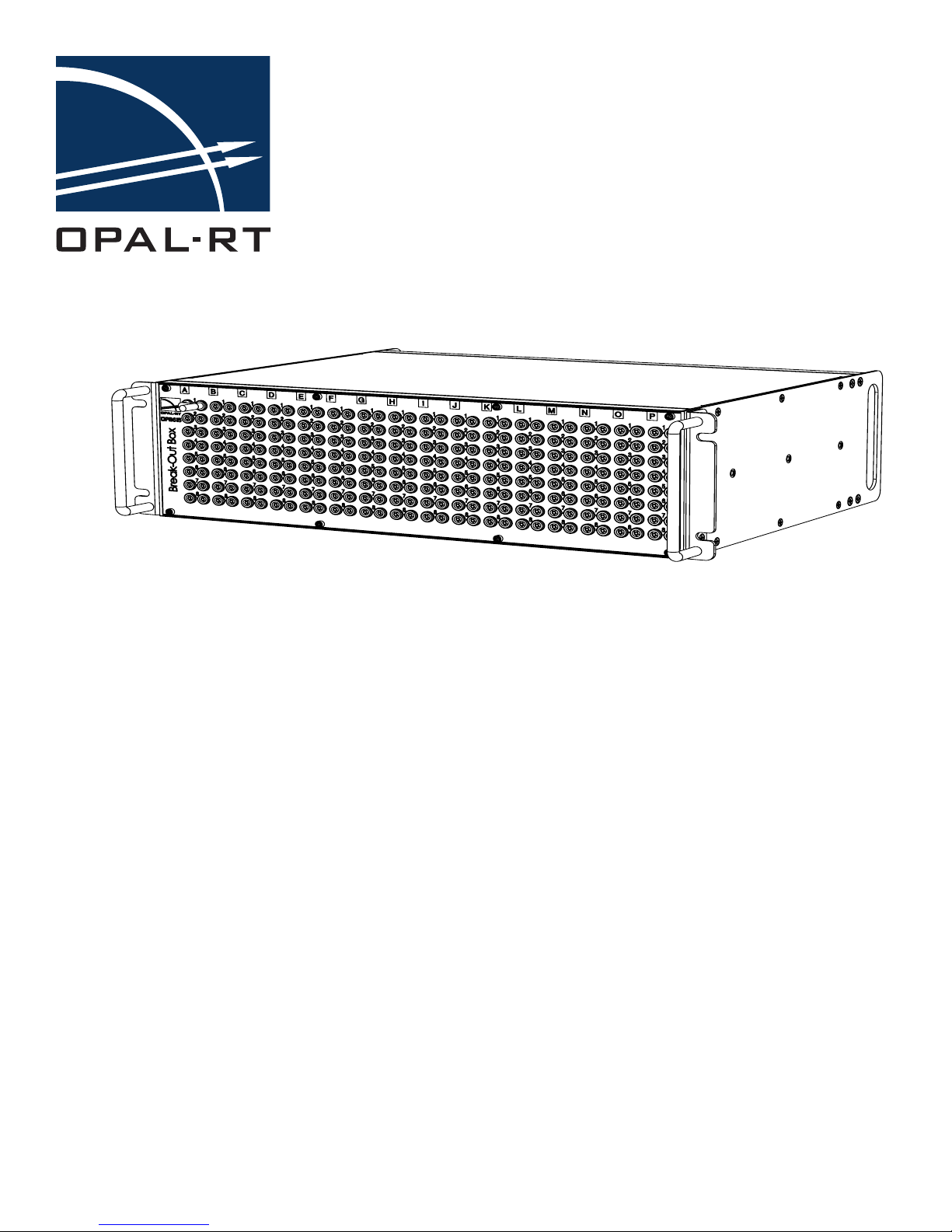
OP8615 Break-Out Box
www.opal-rt.com
User Manual
Page 2

Published by
OPAL-RT Technologies, Inc. 1751 Richardson, suite 2525 Montreal, Quebec, Canada H3K 1G6
www.opal-rt.com
© 2014 OPAL-RT Technologies, Inc. All rights reserved
Printed in Canada
Page 3

CONTENTS
OP8615 BREAK-OUT BOX ................................................................................................... 5
INTRODUCTION ................................................................................................................ 5
Features ......................................................................................................................................... 5
PIN ASSIGNMENTS .......................................................................................................... 6
Connector Diagram ........................................................................................................................ 6
Connector Pin Assignments ..........................................................................................................7
Connector Requirements ............................................................................................................... 9
SPECIFICATIONS ............................................................................................................ 10
OP8615 User Guide 3
Page 4

OP8615 Break-Out Box
4 OP8615 User Guide
Page 5
OP8615 Break-Out Box
Introduction
OP8615 BREAK-OUT BOX
INTRODUCTION
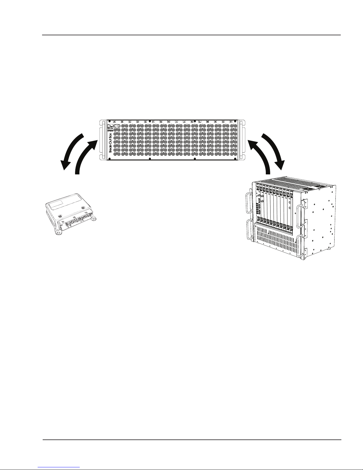
The break-out box provides easy access to all signals on the I/O connectors. Using the OP8615 breakout box, you manually generate circuit faults (open circuit and short circuit) using jumpers to either
break contact or connect a circuit. You can analyse and test electronic equipment by specifically testing
each component and its connection.
Break-Out Box
Use
Break-Out Box
Controller
Simulator
Figure 1: Break-out box use illustration
By installing the break-out box as a link between the unit under test (ECU, motor controller, etc.) and
the simulator, you can insert a fault at any point in the test to assess how the unit reacts to the fault.
You can check and reconnect signals without changing the existing cable harness.
Features
• 128 low current circuits (5 amp)
OP8615 User Guide 5
Page 6
OP8615 Break-Out Box
BLACK
Pin Assignments
PIN ASSIGNMENTS
Connector Diagram
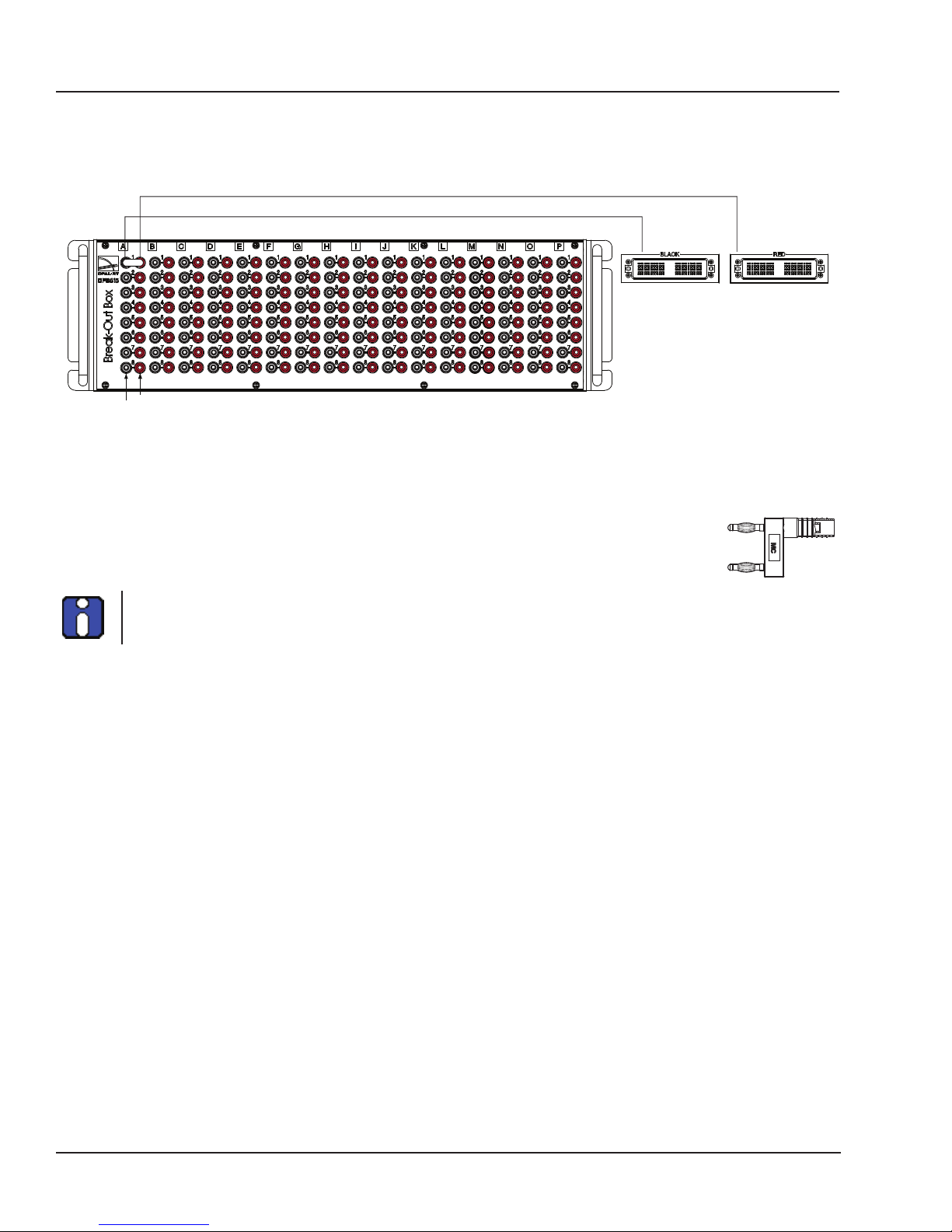
Each pair of jacks connects from a channel on the unit under test to a channel on the simulator.
OP8615 FRONT VIEW OP8615 REAR VIEW
RED -
OUT TO CONTROLLER
RED
BLACK -
IN FROM SIMULATOR
Figure 2: Front banana jacks path to connector
Faults are manually created by removing a jumper into the desired channel jacks. The jumper used for
the break-out box are supplied.
In the event that replacements are needed, we recommend using the original part
(SKS2-12L/1SA/N, 12mm jumper, 2mm), or an equivalent.
As a general guideline, cables from the Break-Out Box to the controller should be connected on the RED
jacks and cables from the simulator to the Break-Out Box should be connected to the BLACK jacks.
6 OP8615 User Guide
Page 7
OP8615 Break-Out Box
1 2 3 4 5 6
Pin Assignments
Connector Pin Assignments
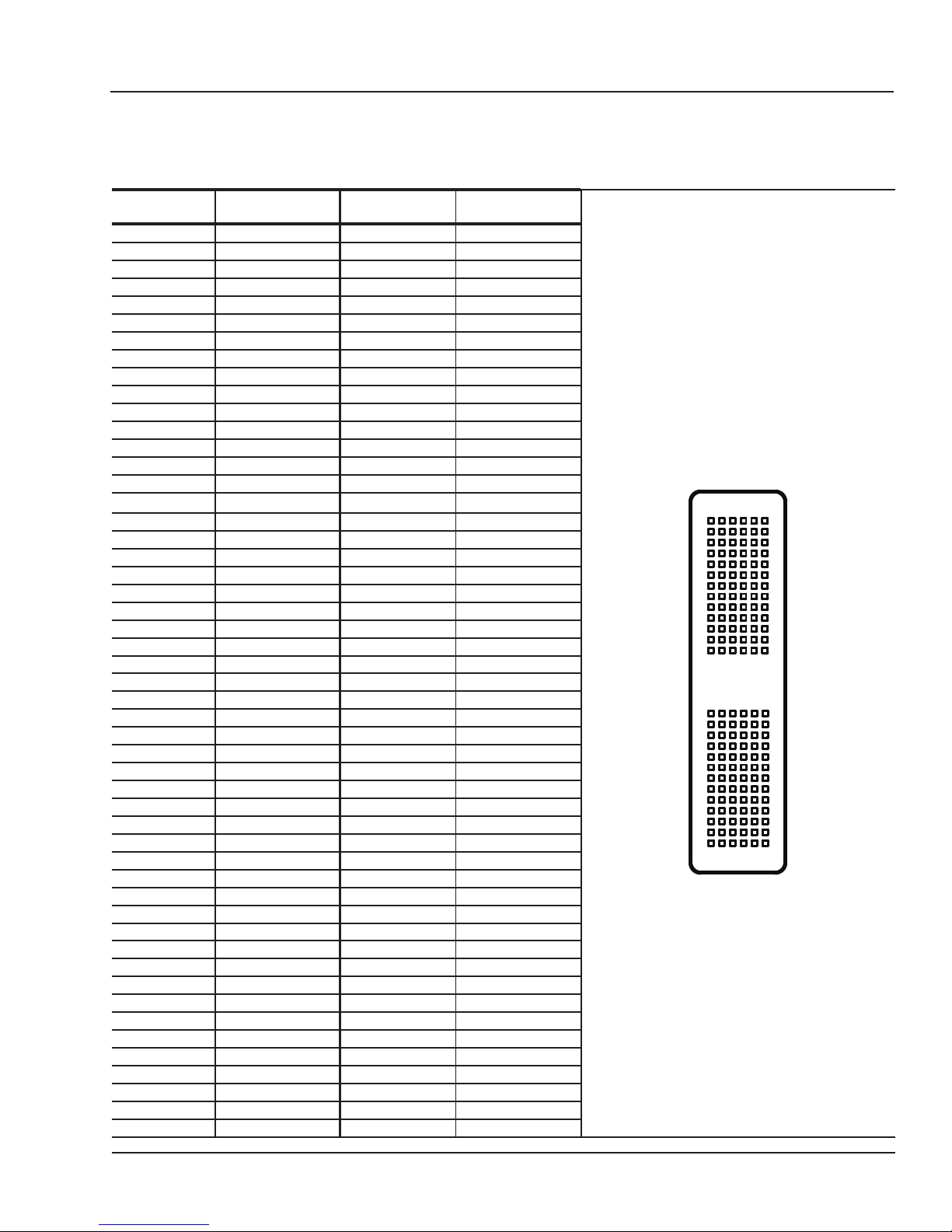
The following table lists the signals available on the front, low current connector and on the system’s
two rear connectors.
Red (left)
breakout pin
Red Rear
connector
Black (right)
breakout pin
Black Rear
connector
A1 1-1 A1 1-1
B1 1-2 B1 1-2
A2 1-3 A2 1-3
B2 1-4 B2 1-4
A3 1-5 A3 1-5
B3 1-6 B3 1-6
A4 1-7 A4 1-7
B4 1-8 B4 1-8
A5 2-1 A5 2-1
B5 2-2 B5 2-2
A6 2-3 A6 2-3
B6 2-4 B6 2-4
C1 2-5 C1 2-5
D1 2-6 D1 2-6
C2 2-7 C2 2-7
1 2 3 4 5 6
D2 2-8 D2 2-8
C3 3-1 C3 3-1
D3 3-2 D3 3-2
C4 3-3 C4 3-3
D4 3-4 D4 3-4
C5 3-5 C5 3-5
D5 3-6 D5 3-6
C6 3-7 C6 3-7
D6 3-8 D6 3-8
A
B
C
D
E
F
G
H
J
K
L
M
N
A
B
C
D
E
F
G
H
J
K
L
M
N
E1 4-1 E1 4-1
F1 4-2 F1 4-2
E2 4-3 E2 4-3
F2 4-4 F2 4-4
E3 4-5 E3 4-5
F3 4-6 F3 4-6
E4 4-7 E4 4-7
F4 4-8 F4 4-8
E5 5-1 E5 5-1
F5 5-2 F5 5-2
E6 5-3 E6 5-3
P
R
S
T
U
V
W
X
Y
Z
a
b
c
P
R
S
T
U
V
W
X
Y
Z
a
b
c
F6 5-4 F6 5-4
G1 5-5 G1 5-5
H1 5-6 H1 5-6
G2 5-7 G2 5-7
H2 5-8 H2 5-8
G3 6-1 G3 6-1
H3 6-2 H3 6-2
G4 6-3 G4 6-3
H4 6-4 H4 6-4
G5 6-5 G5 6-5
H5 6-6 H5 6-6
G6 6-7 G6 6-7
H6 6-8 H6 6-8
J1 7-1 J1 7-1
K1 7-2 K1 7-2
J2 7-3 J2 7-3
OP8615 User Guide 7
Page 8

OP8615 Break-Out Box
Pin Assignments
Red (left)
breakout pin
Red Rear
connector
Black (right)
breakout pin
Black Rear
connector
K2 7-4 K2 7-4
J3 7-5 J3 7-5
K3 7-6 K3 7-6
J4 7-7 J4 7-7
K4 7-8 K4 7-8
J5 8-1 J5 8-1
K5 8-2 K5 8-2
J6 8-3 J6 8-3
K6 8-4 K6 8-4
L1 8-5 L1 8-5
M1 8-6 M1 8-6
L2 8-7 L2 8-7
M2 8-8 M2 8-8
L3 9-1 L3 9-1
M3 9-2 M3 9-2
L4 9-3 L4 9-3
M4 9-4 M4 9-4
L5 9-5 L5 9-5
M5 9-6 M5 9-6
L6 9-7 L6 9-7
M6 9-8 M6 9-8
N1 10-1 N1 10-1
P1 10-2 P1 10-2
N2 10-3 N2 10-3
P2 10-4 P2 10-4
N3 10-5 N3 10-5
P3 10-6 P3 10-6
N4 10-7 N4 10-7
P4 10-8 P4 10-8
N5 11-1 N5 11-1
P5 11-2 P5 11-2
N6 11-3 N6 11-3
P6 11-4 P6 11-4
R1 11-5 R1 11-5
S1 11-6 S1 11-6
R2 11-7 R2 11-7
S2 11-8 S2 11-8
R3 12-1 R3 12-1
S3 12-2 S3 12-2
R4 12-3 R4 12-3
S4 12-4 S4 12-4
R5 12-5 R5 12-5
S5 12-6 S5 12-6
R6 12-7 R6 12-7
S6 12-8 S6 12-8
T1 13-1 T1 13-1
U1 13-2 U1 13-2
T2 13-3 T2 13-3
U2 13-4 U2 13-4
T3 13-5 T3 13-5
U3 13-6 U3 13-6
T4 13-7 T4 13-7
U4 13-8 U4 13-8
T5 14-1 T5 14-1
U5 14-2 U5 14-2
T6 14-3 T6 14-3
8 OP8615 User Guide
Page 9

Red (left)
breakout pin
U6 14-4 U6 14-4
V1 14-5 V1 14-5
W1 14-6 W1 14-6
V2 14-7 V2 14-7
W2 14-8 W2 14-8
V3 15-1 V3 15-1
W3 15-2 W3 15-2
V4 15-3 V4 15-3
W4 15-4 W4 15-4
V5 15-5 V5 15-5
W5 15-6 W5 15-6
V6 15-7 V6 15-7
W6 15-8 W6 15-8
X1 16-1 X1 16-1
Y1 16-2 Y1 16-2
X2 16-3 X2 16-3
Y2 16-4 Y2 16-4
X3 16-5 X3 16-5
Y3 16-6 Y3 16-6
X4 16-7 X4 16-7
Y4 16-8 Y4 16-8
Red Rear
connector
Black (right)
breakout pin
Black Rear
connector
Table 1: Low current connector pin assignments
OP8615 Break-Out Box
Pin Assignments
Connector Requirements
Connectors require specific male connectors. The part numbers provided are for reference purposes
only and may differ according to supplier and country.
Part Part Number Description
Connector 110535-000 ITT Cannon DL1-156 ,RECTANGULAR, PLUG, 156POS, PANEL
PIN 030-2409-003 ITT Cannon CONTACT, PIN, 22-20AWG, CRIMP
Backshell DL1-J/S ITT Cannon JUNCTION SHELL KIT, DL1, CONNECTOR
handle 204-0016-000 ITT Cannon ACTUATING HANDLE KIT, DL CONNECTOR
Key way 320-0021-005 POLARIZING POST KIT - Center Mounting for DL1/2, DLM1/2
OP8615 User Guide 9
Page 10

OP8615 Break-Out Box
Specifications
SPECIFICATIONS
Product name Break-Out Box
Part number OP8615
Number of channels Low current: 128 channels, 5A
Voltage range 0-30 Vdc
Form factor 3 U
Dimensions 13.33 x 48.26 x 30.8cm HxWxD (5.25” x 19” x 12.125”)
I/O connector Low current: ITT Cannon DL1-156, SEB2-R 2 mm banana jack with 12 mm
jumper
Operating temperature 10 to 40 ºC (50 to 104ºF)
Storage temperature -55 to 85ºC (-67 to 185ºF)
Relative humidity 10 to 90%, non condensing
Maximum altitude 2,000 m (6562 ft.)
10 OP8615 User Guide
Page 11

OP8615 Break-Out Box
Specifications
OP8615 User Guide 11
Page 12

CONTACT
OPAL-RT Corporate Headquarters
1751 Richardson, Suite 2525
Montréal, Québec, Canada
H3K 1G6
Tel.: 514-935-2323
Toll free: 1-877-935-2323
Technical Services
www.opal-rt.com/support
Note:
While every effort has been made to ensure
accuracy in this publication, no responsibility can
be accepted for errors or omissions. Data may
change, as well as legislation, and you are strongly
advised to obtain copies of the most recently
issued regulations, standards, and guidelines.
This publication is not intended to form the basis
of a contract.
UG14-24164-OP1
06/2014
© OPAL-RT Technologies Inc.
 Loading...