

Page 1

OP8111 HIGH VOLTAGE AMPLIFIER
USER GUIDE
www.opal-rt.com
Page 2

Published by
OPAL-RT Technologies, Inc. 1751 Richardson, suite 2525 Montreal (Quebec) Canada H3K 1G6
www.opal-rt.com
© 2015 OPAL-RT Technologies, Inc. All rights reserved
Printed in Canada
Page 3

CONTENTS
INTRODUCTION ..................................................................................................................................... 4
APPLICATIONS .........................................................................................................................................................4
STARTUP PROCEDURE ......................................................................................................................... 4
POWERING UP .................................................................................................................................... 4
TECHNICAL SPECIFICATIONS .............................................................................................................. 5
CONNECTION DETAILS ...................................................................................................................... 5
SPECIFICATIONS ................................................................................................................................ 8
OP8111 User Manual OPAL-RT Technologies 3
Page 4
INTRODUCTION
PHASE C
OP8
1
1
1
PHASE B
PHASE A
UP On
UP Default
DOWN On
DOWN Default
UP On
UP Default
DOWN On
DOWN Default
UP On
UP Default
DOWN On
DOWN Default
Power Good
AC/ON
Phase A Phase B Phase C Power Good AC/ON
Powering up
INTRODUCTION
The OP8111 high voltage amplifier is transformer based and designed for use with an OPAL-RT
simulator or as a standalone amplifier. It provides up to 3 isolated high voltages up to ±160Vrms / 50VA
(maximum) and the maximum input voltage range is ±10V_max before output clamping.
Outputs can be configured in Wye or Delta.
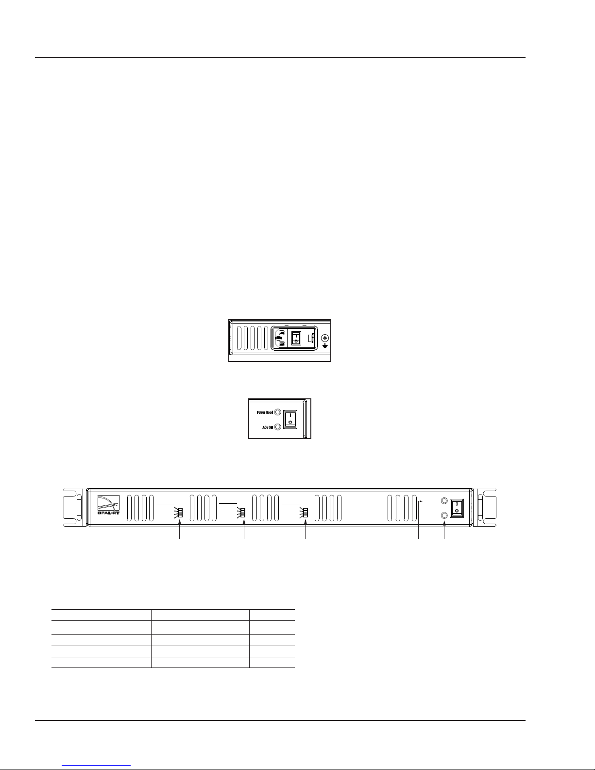
The amplifier is designed with connections for one to three phases, depending on the configuration
requested. Each phase is equipped with two connectors, and four status LEDs.
Typical use cases are motor and power grid emulation.
STARTUP PROCEDURE
POWERING UP
The unit has two power switches, for ease of use. Follow these steps to properly power up the OP8111
Power Amplifier:
1. Press the switch at the rear of the unit to put it in the ON position
2. Press the switch at the front of the unit to put it in the ON position. Both Power Good and AC/ON
LEDs must be on.
3. Verify Status
The OP8111 voltage amplifier is equipped with a series of LED indicators that display the phase
status:
Once the front power switch is in the ON position, fans will initially run at maximum speed before
returning to a slower, nominal speed.
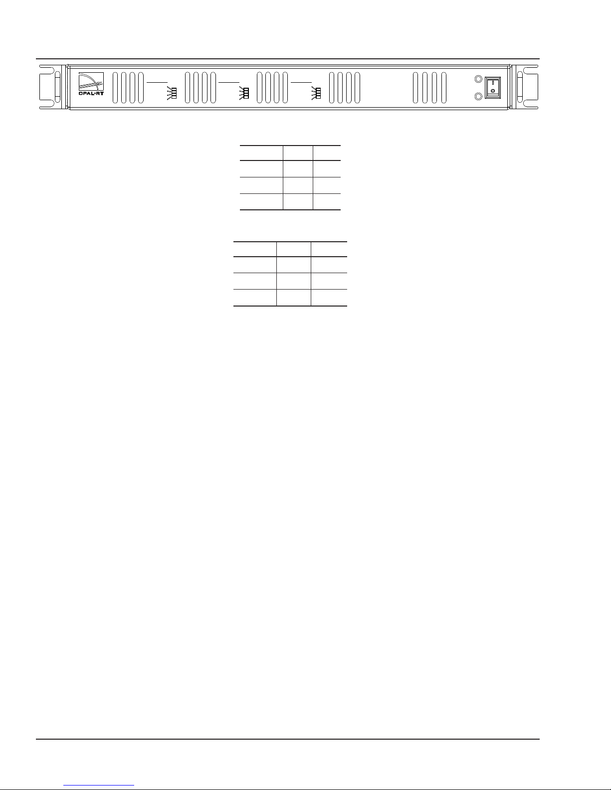
Each phase has 4 LEDs to indicate its status:
DESIGNATION POWER UP FAU LT
UP On Off Red
UP Default Green Off
DOWN On Off Red
DOWN Default Green Off
4. Connect the load
5. Adjust the required output voltage (on the target) for the test.
4 OPAL-RT Technologies OP8111 User Manual
Page 5
TECHNICAL SPECIFICATIONS
CONNECTION DETAILS
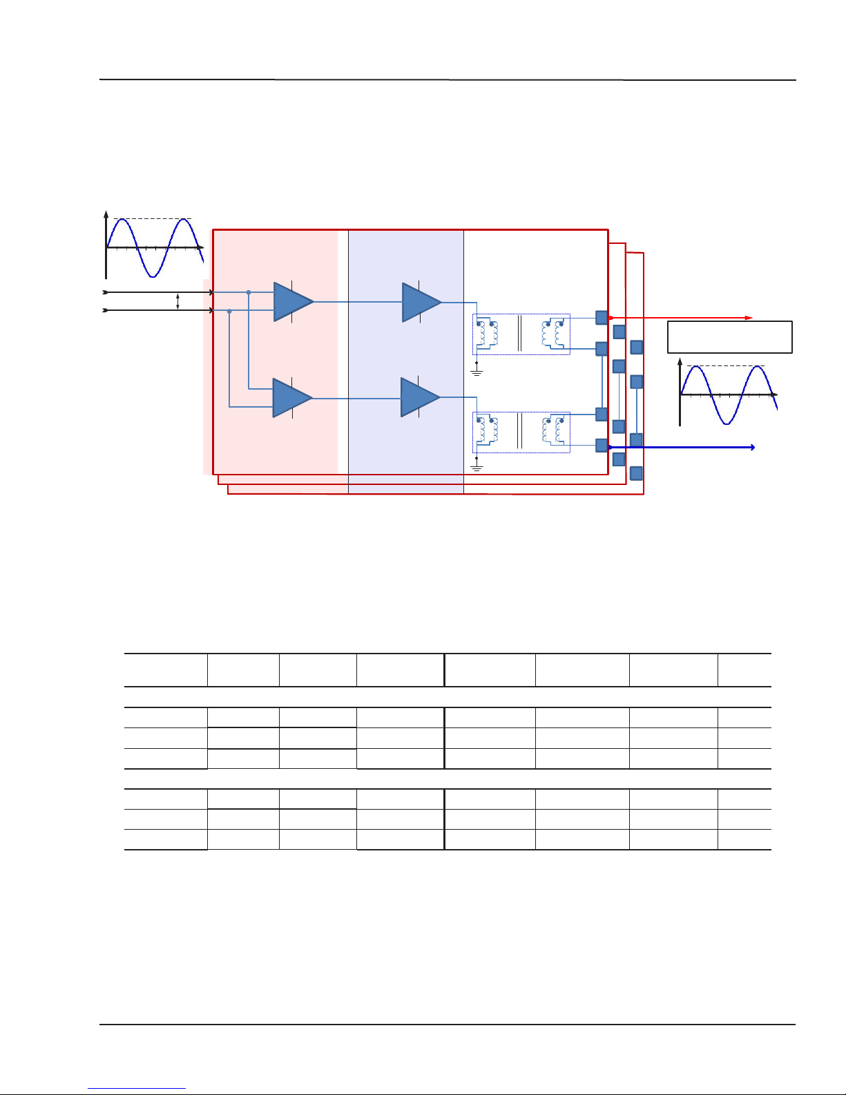
The following diagram provides an overview of the amplifier function.
OP8111 Power Amplifier,
Phase A Principle Overview
40-1200Hz
Vi n
Ref_P
Ref_N
Differential Stage
+15V
G=1
+
-15V
+15V
+
G=1
-
-15V
Channel 2
1st Amplification
Channel 1
Stage
+24V
G=2
-24V
+24V
G=2
-24V
2nd Amplification
Stage*
40 -1200Hz
40 -1200Hz
T1-Secondary
T2-Secondary
T1-Primary
T2-Primary
Phase A
Phase B
1
1
2
2
3
3
4
4
Technical Specifications
Connection Details
Phase C
Vout_A
3 phases
1
2
3
4
80 Vrms-160 Vrms/50VA
Ground ISO_A
*Serial or parallel, depending on output voltage requirements
Figure 6: OP8111 high voltage amplier, synoptic - parallel conguration
The following table provides ratings and bandwidth for inputs and output signals. Note that each
channel is enabled by default.
Input Signal Gain ±1%
(no load)
Serial configuration
Vout_a 24 22 40Hz-1200Hz SIM A 0 to 160Vrms 40Hz-1200Hz 50W
Vout_b 24 22 40Hz-1200Hz SIM B 0 to 160Vrms 40Hz-1200Hz 50W
Vout_c 24 22 40Hz-1200Hz SIM C 0 to 160Vrms 40Hz-1200Hz 50W
Parallel Configuration
Vout_a 11.85 10.9 40Hz-1200Hz SIM A 0 to 80Vrms 40Hz-1200Hz 50W
Vout_b 11.85 10.9 40Hz-1200Hz SIM B 0 to 80Vrms 40Hz-1200Hz 50W
Vout_c 11.85 10.9 40Hz-1200Hz SIM C 0 to 80Vrms 40Hz-1200Hz 50W
Gain ±1%
(with load)
Frequency Output Signal Voltage Frequency Output
Power
Table 8: Signal bandwidths
OP8111 User Manual OPAL-RT Technologies 5
Page 6
Technical Specifications
Connection Details
OP8
PHASE C
UP On
UP Default
DOWN On
1
1
1
DOWN Default
PHASE B
UP On
UP Default
DOWN On
DOWN Default
PHASE A
UP On
UP Default
DOWN On
DOWN Default
Power Good
AC/ON
Figure 7: OP8111 front
PHASE IN+ IN-
A 1 9
B 1 9
C 1 9
Table 9: Input DB9 pinout
PHASE OUT+ OUT-
A A+ A-
B B+ B-
C C+ C-
Table 10: Output PIN OUT, 2 position screw terminal block
6 OPAL-RT Technologies OP8111 User Manual
Page 7
Technical Specifications
G= 2
Primary
Secondary
1
2
1
4
2
3
G= 2
Primary
Secondary
3
4
1
4
2
3
5
6
7
8
Amplifier Case
Amplifier Output Terminals
160 Vrms/50VA
Output
5
6
7
8
G= 2
Primary
Secondary
1
2
1
4
2
3
5
6
7
8
G= 2
Primary
Secondary
3
4
1
4
2
3
5
6
7
8
Amplifier Case
Amplifier Output Terminals
80 Vrms/50VA
Output
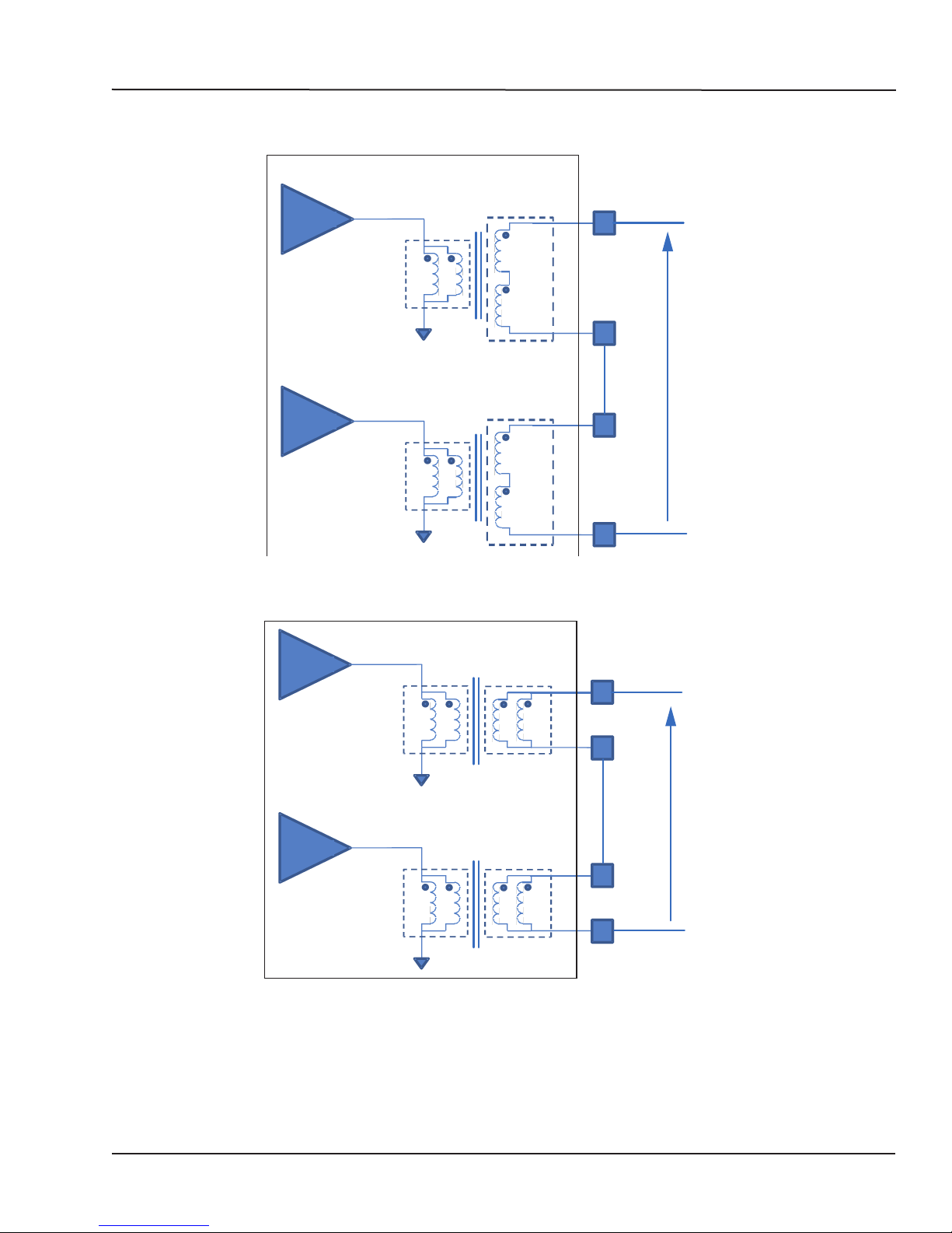
Figure 8 provides an example of a transformer conguration, with a second using the same
connections.
Connection Details
Figure 8: Transformer connection, serial conguration
Figure 9: Transformer connection, parallel conguration
OP8111 User Manual OPAL-RT Technologies 7
Page 8

Technical Specifications
Specifications
SPECIFICATIONS
Product name OP8111
Input Power 110/230 Vac ; 50/60Hz
Analog inputs
Connectors DB9
Coupling DC, Differential
Diff input impedance 10KΩ
Analog outputs
Connectors 2 positions screw terminal block
Coupling DC, referenced to its HVGND
Voltage range Serial: ±160Vrms /50VA
Parallel: ± 80Vrms / 50VA
Output regulation 7%
Protections Thermal and short circuit to ground.
Max Current Serial Config. = 0.3125A_rms
Parallel Config. = 0.625A_rms
3 phases configuration Wye ( default)
no sinking capability.
Output impedance 4Ω ±5%
Phase lag ( Out / In) ≤ 1°over the frequency bandwidth.
Bandwidth 40Hz - 1200Hz
Nominal operating frequency 45Hz - 65Hz
Dimensions 18.000" L × 17.000" W × 1.728" H
weight 12 Kg
8 OPAL-RT Technologies OP8111 User Manual
Page 9

OP8111 User Manual OPAL-RT Technologies 9
Page 10

10 OPAL-RT Technologies OP8111 User Manual
Page 11

CONTACT
OPAL-RT Corporate Headquarters
1751 Richardson, Suite 2525
Montréal, Québec, Canada
H3K 1G6
Tel.: 514-935-2323
Toll free: 1-877-935-2323
Technical Services
www.opal-rt.com/support
Note:
While every effort has been made to ensure
accuracy in this publication, no responsibility
can be accepted for errors or omissions. Data
may change, as well as legislation, and you are
strongly advised to obtain copies of the most
recently issued regulations, standards, and
guidelines.
This publication is not intended to form the
basis of a contract.
UM15-52356 RVN 2.0
06/2016
© OPAL-RT Technologies Inc.
 Loading...