

Page 1
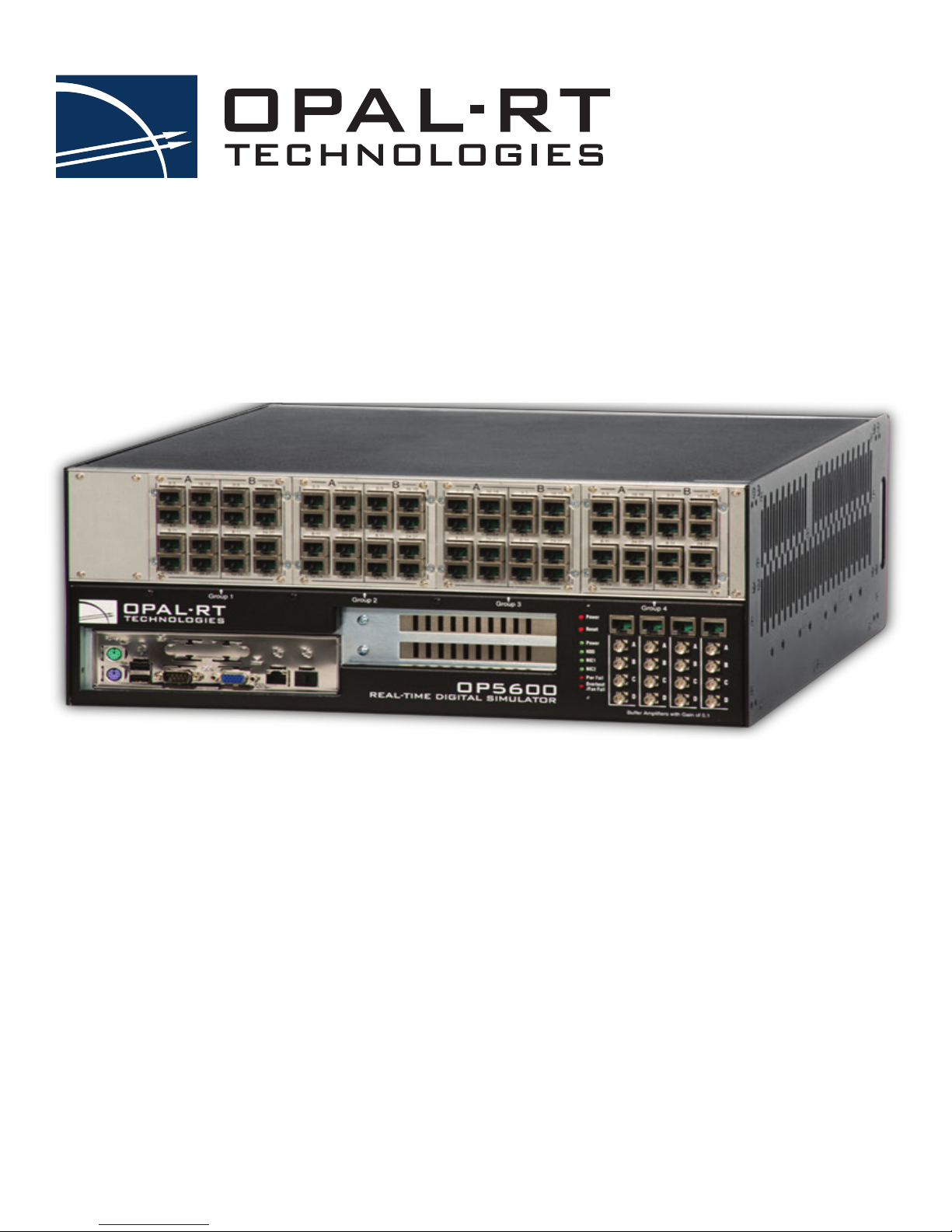
OP5600 SERIES V3
Real-Time Digital Simulator
OP5650 User Manual
Artix 7
www.opal-rt.com
Page 2

Published by
OPAL-RT Technologies, Inc. 1751 Richardson, suite 2525 Montreal, Quebec, Canada H3K 1G6
www.opal-rt.com
©2018 OPAL-RT Technologies, Inc. All rights reserved
Printed in Canada
Page 3
SYMBOL DEFINITIONS
!
!
The following table lists the symbols used in this document to denote certain conditions:
Symbol Definition
ATTENTION: Identifies information that requires special consideration
TIP: Identifies advice or hints for the user, often in terms of performing a task
REFERENCE _ INTERNAL: Identifies an additional source of information within the bookset.
CAUTION
Indicates a situation which, if not avoided, may result in equipment or work (data) on the system being
damaged or lost, or may result in the inability to properly operate the process.
Indicates a situation where users must observe precautions for handling electrostatic sensitive devices.
CAUTION: Indicates a potentially hazardous situation which, if not avoided, may result in minor or
moderate injury. It may also be used to alert against unsafe practices.
WARNING: Indicates a potentially hazardous situation which, if not avoided, could result in serious injury or
death.
iii OPAL-RT Technologies OP5600/OP5650 User Manual
Page 4

Page 5

CONTENTS
RECEIVING AND VERIFICATION ........................................................................................................ 7
standard hardware .............................................................................................................................................. 7
OP5600 SERIES/OP5650 SIMULATOR .................................................................................................. 8
INTRODUCTION .................................................................................................................................. 8
SIMULATOR ARCHITECTURE ............................................................................................................ 9
configuration options .......................................................................................................................................... 9
Simulator Architecture Example ...................................................................................................................................... 9
INSTALLATION AND CONFIGURATION ............................................................................................ 10
HARDWARE CONFIGURATION ......................................................................................................... 11
back connectors ...............................................................................................................................................13
Connecting the Ground Screw ...................................................................................................................................... 14
DB37F CONNECTIONS ..................................................................................................................... 15
OP5650 DB37 PIN ASSIGNMENTS .................................................................................................. 17
RJ45 CONNECTIONS ........................................................................................................................ 18
RJ45 CHANNEL ASSIGNMENTS ..................................................................................................... 19
connecting monitoring devices...........................................................................................................................20
SPECIFICATIONS ............................................................................................................................ 21
FLAT CARRIER SPECIFICATIONS .................................................................................................... 21
LIMITED WARRANTY ............................................................................................................................ 23
Limited warranty .............................................................................................................................................. 23
return poLicy ...................................................................................................................................................23
excLusions ........................................................................................................................................................ 23
warranty Limitation and excLusion ....................................................................................................................24
discLaimer of unstated warranties ..................................................................................................................24
Limitation of LiabiLity ........................................................................................................................................24
5 OPAL-RT Technologies OP5600/OP5650 User Manual
Page 6

OP5600/OP5650 User Manual OPAL-RT Technologies 6
Page 7

Receiving and Verification
!
RECEIVING AND VERIFICATION
After opening the package, remove the equipment and components. Make sure that all the items
described in “standard hardware” are actually in the box and are undamaged.
standard hardware
The OP5650 real-time simulator includes the following basic hardware:
Item Description Part Number
OP5650 Simulator with Linux -based real-time O/S with PC
System Integration binder CD (documentation, models, licenses)software CD
Mini-BNC cables (4) 2 m (6 ft 6”) adapter cables for mini-BNC to BNC. 75 Ohms
RJ45 cables (5) 61cm (24”) RJ45 cables BLACK
Synchronization cable Plastic optical fiber patch cord 3M T00-0811
DB37M breakout board Provides extended space for connections T00-4069
Loopback Kit DB37 TestBoard
Power cable 1.83 m (6’) power cord, black (10A 125V)
Screws and rubber feet kit Extra if needed N/A
or OP5650-IO without CPU
Integration documents
simplex
61cm (24”) RJ45 cables WHITE
61cm (24”) RJ45 cables RED
61cm (24”) RJ45 cables GREEN
305cm (120”) RJ45 cable BLUE
Loopback Flat cable
Power cable
For Quick testing and Troubleshooting
Power Cord 6ft European (Schuko CEE7/7 to C13) - For Type E
and Type F
Power Cord 6ft Australia (AS3112 to C13) - Type I
Power Cord 6ft Brazil (NBR14136 to C13) - Type N
Power Cord 6ft China (GB2099 to C13) - Type I
Power Cord 6ft India (IS16A3 to C13) - Type D
Power Cord 6ft Switzerland (SEV1011 to C13) - Type J
Power Cord 6ft UK (BS1363 to C13) - Type G
N/A
T00-0719
T00-0723
T00-0724
T00-0725
T00-0726
T00-0817
126-0361
113-0737
113-0799
T00-0833
T00-0783
T00-0784
T00-0795
T00-0775
T00-0794
T00-1836
T00-0848
optional hardware
Item Description Part Number
MUSE transceiver Avago AFBR-57R5APZ T00-0315
MUSE cable LC-LC multimode 850nm optical fiber T00-0782
OPAL-RT strongly recommends the use of anti-static wrist straps whenever handling any electronic
device provided by OPAL-RT. Damage resulting from electrostatic charges will not be covered by the
manufacturer’s warranty.
Disconnect power before servicing
The OP5650 may be subjected to EMI when installed in proximity to other devices. Make sure to connect
the OP5650 ground to the rack to prevent any EMI related damage to the simulator.
7 OPAL-RT Technologies OP5600/OP5650 User Manual
Page 8

OP5600 Series/OP5650 Simulator
Introduction
OP5600 SERIES/OP5650 SIMULATOR
INTRODUCTION
The OP5650 is a complete simulation system, that contains a powerful target computer, a
reconfigurable FPGA and signal conditioning for up to 256 I/Os. The design makes it easy to use with
standard connectors (DB37, RJ45, SFP and mini-BNC) without the need for input/output adaptors and
allows quick connections for monitoring I/O signals. It is designed to be used either as a desktop, shelf
top, or mounted in a standard 19’’ rack.
The front of the chassis provides access to the target computer’s standard connectors, and monitoring
interfaces and connectors, while the back of the chassis provides access to the I/O connectors, power
cable and main power switch.
Inside, the main housing is divided into two sections, each with a specific purpose:
In its standard configuration, the lower part of the chassis contains a powerful target computer that
can be added to a network of simulators or can act as a standalone. The target computer used to run
simulations built with OPAL-RT’s RT-LAB or HYPERSIM software simulation platform includes the
following features:
• ATX motherboard
• Linux-based real-time operating system
• Xeon E5 Intel CPU with 4, 8, 16 and 32 processor cores, up to 3.2GHz
• 10MB Cache Memory per 4 cores
• up to 32GB of DRAM,
• 512GB SSD disk,
• Space to install 2 PCI with risers, or 3 PCIe boards.
• Power consumption: 600W Max.
The upper section contains the high-speed FPGA and the conditioning modules for up to 256 I/Os. The
main features include:
• Xilinx Artix 7 FPGA 200T, programmable from the target computer via PCIe or MUlti-System
Expansion (MUSE). The FPGA is used to execute models designed with the OPAL-RT RT-XSG
tool, and manage the I/O lines. It exchanges data with the real-time simulations running on the
target computer CPUs via the PCIe link.
• Flat carrier capable of connecting any combination of up to 8 type B mezzanine boards.
OP5600/OP5650 User Manual OPAL-RT Technologies 8
Page 9
OP5600 Series/OP5650 Simulator
Simulator Architecture
SIMULATOR ARCHITECTURE
configuration options
The OP5650 is available in a number of different configurations that make it easier to integrate into your
environment:
Product Configuration Description
OP5650-4 OP5650 RCP/HIL Artix 7 FPGA-based Real-Time Simulator - 4 cores (4U, Xeon E5, 4 Cores, 3.0 GHz,
OP5650-8 OP5650 RCP/HIL Artix 7 FPGA-based Real-Time Simulator - 8 cores (4U, Xeon E5, 8 Cores, 3.2 GHz,
OP5650-16 OP5650 RCP/HIL Artix 7 FPGA-based Real-Time Simulator - 16 cores (4U, Xeon E5, 2x8 Cores, 3.2 GHz,
OP5650-32 OP5650 RCP/HIL Artix 7 FPGA-based Real-Time Simulator - 32 cores (4U, Xeon E5, 2x16 Cores, 2.3
Simulator Architecture Example
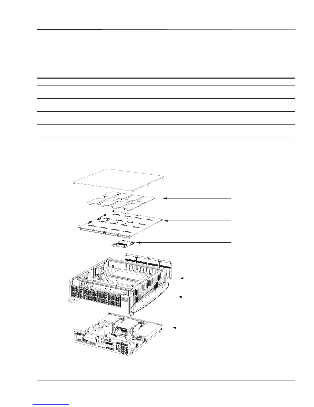
The example shown is only to illustrate how the OP5650 is assembled. OPAL-RT strictly prohibits users
from opening the OP5650. Opening the unit will render the warranty null and void.
10M, 16GB, 512GB SSD)
20M, 16GB, 512GB SSD)
2x20M, 2x16GB, 512GB SSD)
GHz, 2x40M, 2x16GB, 512GB SSD)
Signal conditioning
modules
Carrier board
OPAL-RT
Artix 7
FPGA board
Upper section
optional rackmount rail
Lower section
Target Computer
9 OPAL-RT Technologies OP5600/OP5650 User Manual
Figure 1: OP5650 with target computer
Page 10
OP5600 Series/OP5650 Simulator
!
Installation and Configuration
INSTALLATION AND CONFIGURATION
Follow this simple installation procedure. Make sure to respect proper grounding, as described in
“Connecting the Ground Screw”.
1. Place the OP5650 on a shelf or a desktop, or install in a traditional rack
2. Connect the power cable to the nearest power outlet
3. Connect the OP5650 to the same network used by the host PC, using the cables provided.
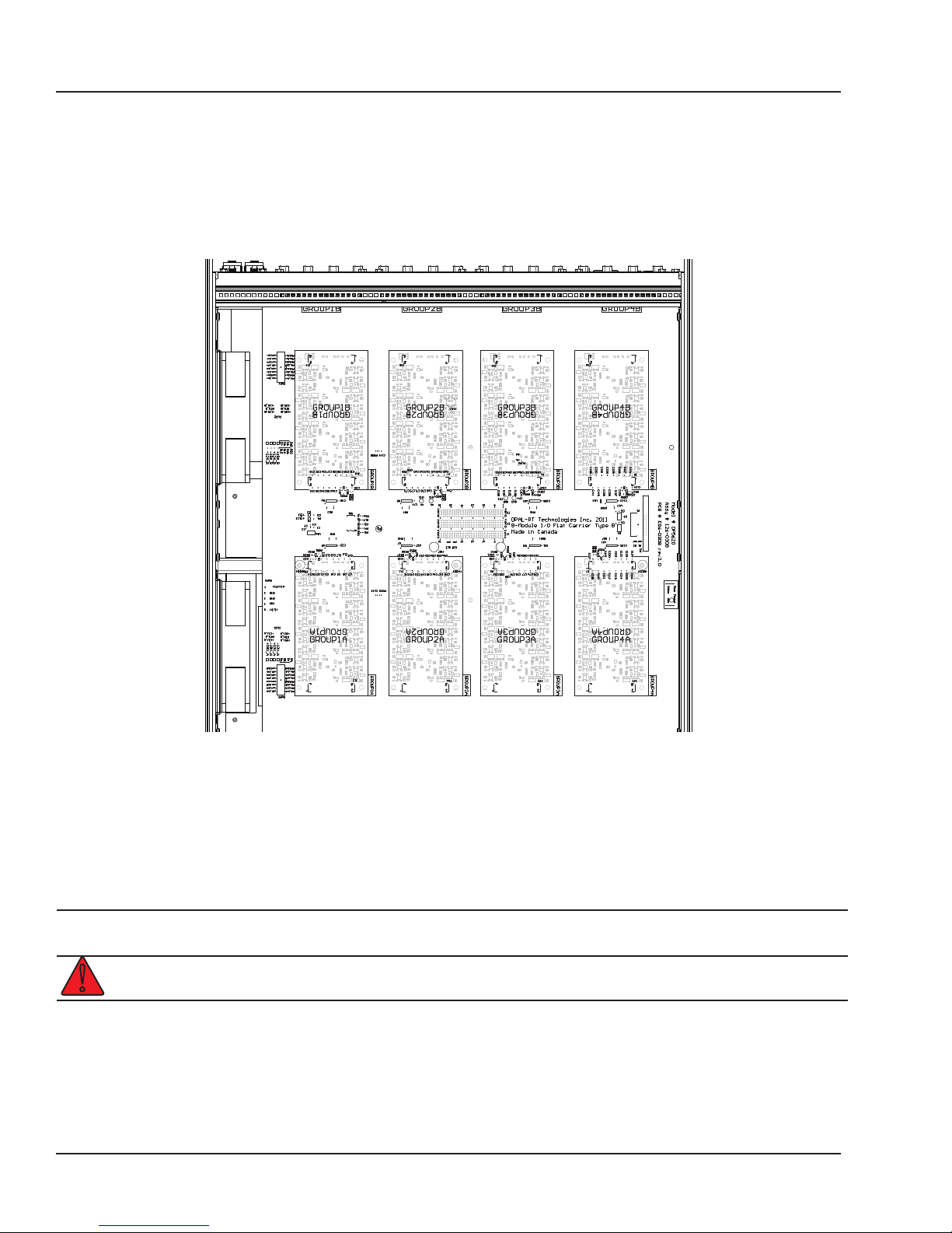
Figure 2: Top view of mezzanines installed on carrier
The top of the chassis can be removed to access the signal conditioning mezzanine boards installed on
the carrier board. The layout and configuration of the boards depends on the selected platform (which
must be factory installed):
At power-up, the carrier will autodetect installed mezzanines and transfer information to the FPGA and
the simulator.
CAUTION
OP5600/OP5650 User Manual OPAL-RT Technologies 10
The system must be powered down before changing mezzanines. Failure to do so may
damage the equipment.
Disconnect power before servicing
Page 11
OP5600 Series/OP5650 Simulator
Hardware Configuration
HARDWARE CONFIGURATION
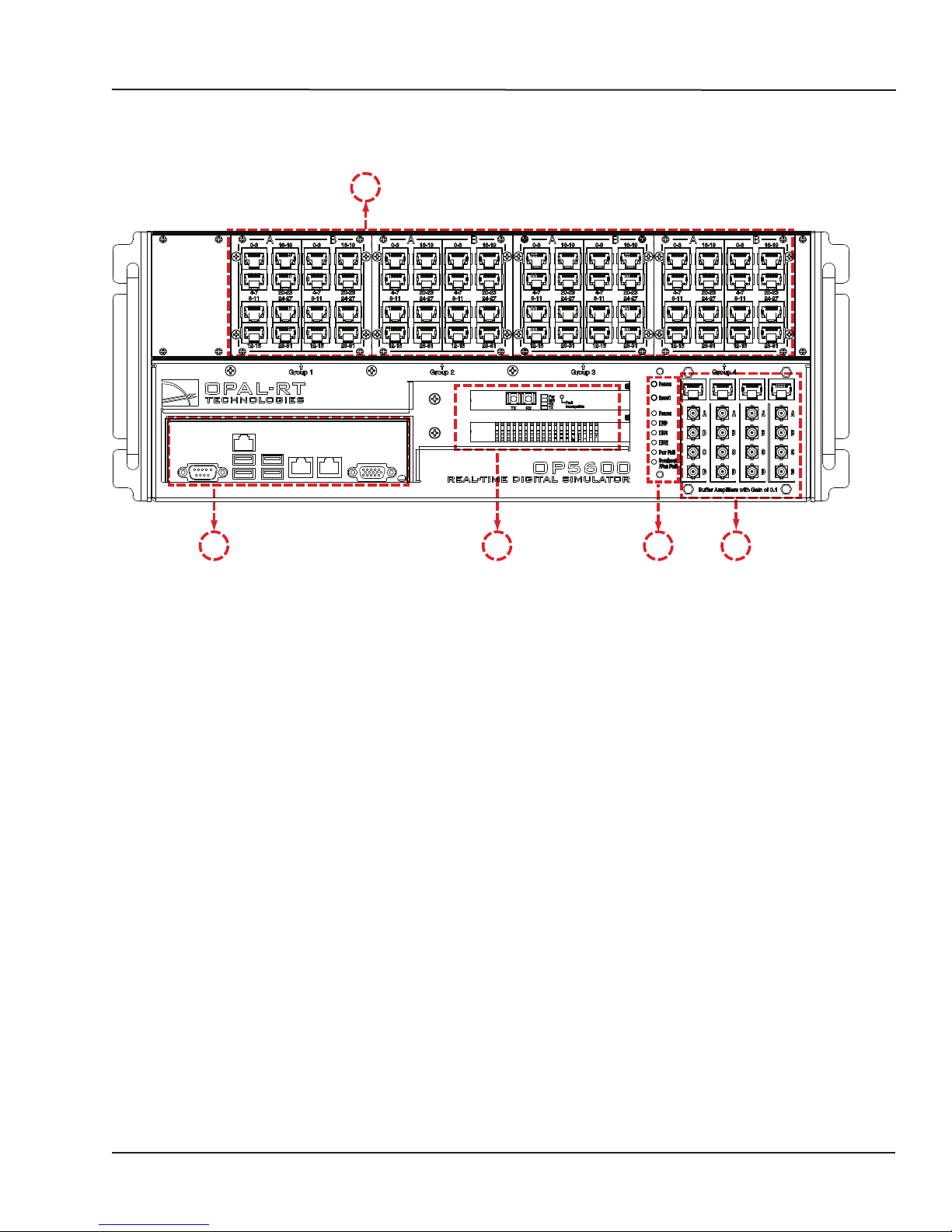
The interfaces on the front of the OP5650 Artix 7 (OP5143) include 4 RJ45 monitoring panels.
A
E D C B
Figure 3: OP5650 front connector panels
A. 4 panels of RJ45 connectors provide connections to monitor output from mezzanine I/O
boards. Each connector is linked to front and b0ack mezzanines on the carrier board. Analog
mezzanines (channels 0-16) will use only the first column of connectors. Digital mezzanines will
use both columns (channels 0-15 in the first column and channels 16-31 on the second column
of connectors). See the mezzanines connector image and the RJ45 pinouts for more detailed
information.
B. Monitoring RJ45 connectors with mini-BNC terminals: RJ45 cables connect from a channel on an
RJ45 panel (B) to one of four RJ45 monitoring connectors (C). Mini-BNC connectors allow for quick
cable connections to monitoring devices (such as an oscilloscope). See “connecting monitoring
devices” for details.
11 OPAL-RT Technologies OP5600/OP5650 User Manual
Page 12

OP5600 Series/OP5650 Simulator
Hardware Configuration
C. Target computer monitoring interface. Two push buttons include POWER in top position to start the
Target computer and RESET in the bottom position to reset the Target computer. There are 6 LED
indicators:
LED NAME Description
Green Power On indicates that the unit is powered up.
Green HDD On indicates that the hard disk drive is operating.
Green NIC1 On indicates that network port 1 is in use.
Green NIC2 On indicates that network port 2 is in use.
Red Power Fail On indicates a power fault.
Red Overheat/Fan Fail On indicates either that unit has overheated or a fan fault.
D. Fiber optic synchronization board (top slot) and optional PCIe connector slot (by default, the lower
space will be covered by a blank plate if there are no optional PCIe boards).
E. Standard computer connectors (left to right): mouse and keyboard, USB ports, monitor, network
ports. Although use of these connectors is optional but not required to use the OP5650, one
network port is required for network connection.
OP5600/OP5650 User Manual OPAL-RT Technologies 12
Page 13
OP5600 Series/OP5650 Simulator
back connectors
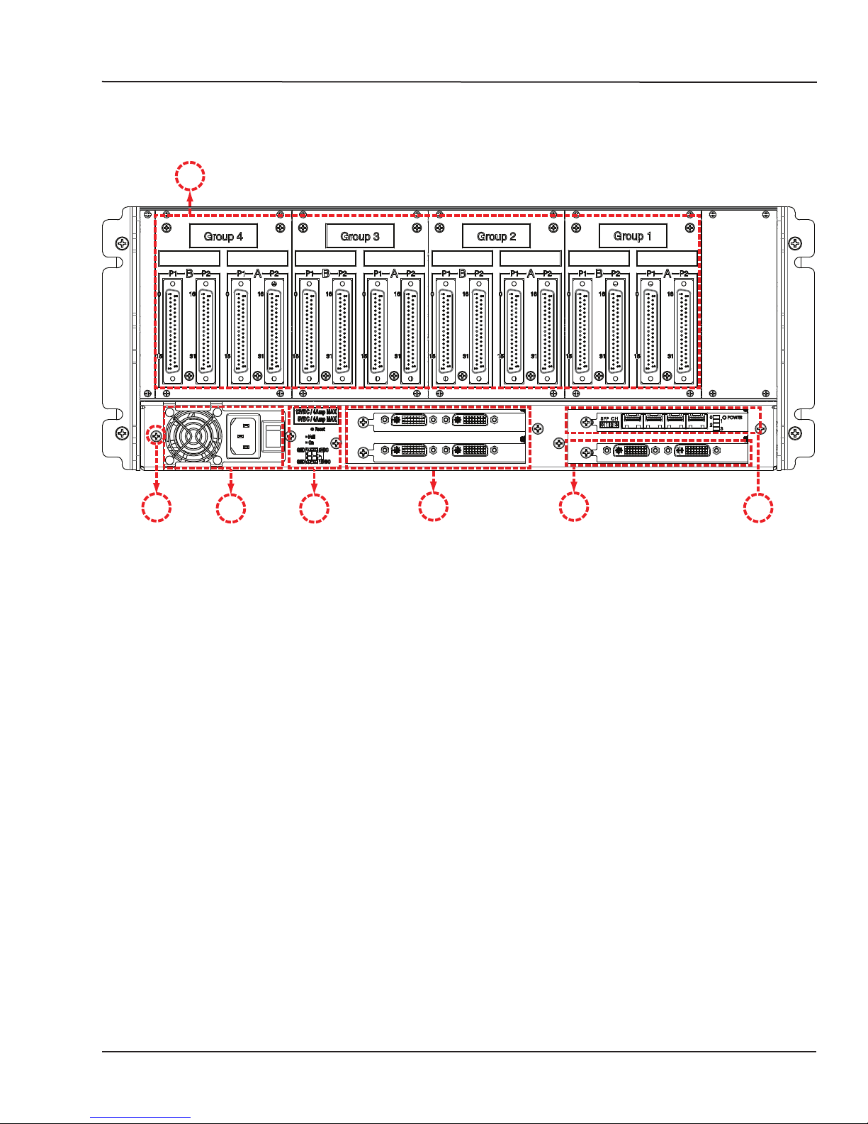
The back connectors may vary, depending on the configuration option selected.
A
Hardware Configuration
B
A. DB37F I/O connectors (see “Table 1: Pin Assignments” for more details). The images (see “DB37F
Connections”) illustrates the links between the mezzanines and the DB37 I/O connectors
B. Ground screw. The OP5650 may be subjected to EMI when installed in proximity to other devices.
Make sure to connect the OP5650 ground to the rack to prevent any EMI related damage to the
simulator (see Figure 7)
C. Power connector and power On/Off switch
D. Power reset and 5/12V power source connector for test purposes:
- Pushbutton reset after 4A overcurrent shutdown
- Red LED indicates fault, green LED indicates nominal function
- Microfit connector for 5V or 12V power allows users to test whether I/Os are functioning. Each
voltage has its own ground reference. Caution: these power sources are not isolated.
E. Optional slots for 2 PCI or 3 PCIe connectors (PCIe only in lower right slot).
F. 4 SFP ports (for MUSE or device interconnection) and status LEDs for each channel (LED 0 =
channel 0, etc.):
- Blinking green: an SFP module is plugged into the port and the bitstream is using Aurora for this
channel
- Continuous green: an SFP module is plugged into the port and the bitstream is not using Aurora
for this channel
- Blinking red: rx_loss is 1
- Continuous red: tx_fault is 1 (these are SFP status signals)
- OFF: no module plugged into the port and no Aurora present in the bitstream for this channel
C
Figure 4: OP5650 rear connector panels (ML605 conguration)
D
E
E
F
13 OPAL-RT Technologies OP5600/OP5650 User Manual
Page 14
OP5600 Series/OP5650 Simulator
Hardware Configuration
Connecting the Ground Screw
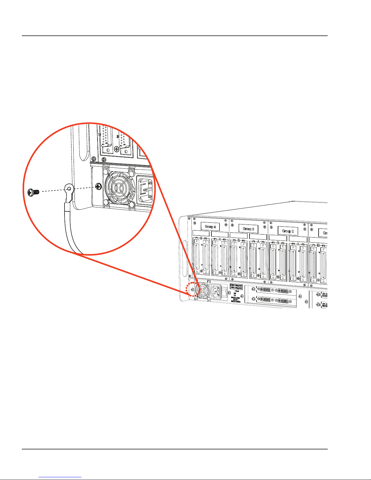
You must connect a grounding cable from the OP5650 ground screw to the rack (or any other strong
ground) to ensure that the OP5650 terminates securely in a ground. Proper grounding will help prevent
electric shocks, protect the OP5650 from voltage spikes (from a variety of causes, including lightening
strikes), and provide increased immunity from EMI by lowering noise levels and emissions.
1. Select a flat braided grounding strap of adequate length (as short as possible provides best
protection), with ring terminals on each end.
2. Attach one ring terminal to the ground screw on the OP5650 (shown in Figure 7)
3. Attach the other ring terminal to the rack using a nut and lockwasher.
Figure 5: Connecting the OP5650 to the ground
OP5600/OP5650 User Manual OPAL-RT Technologies 14
Page 15
OP5600 Series/OP5650 Simulator
DB37F Connections
DB37F CONNECTIONS
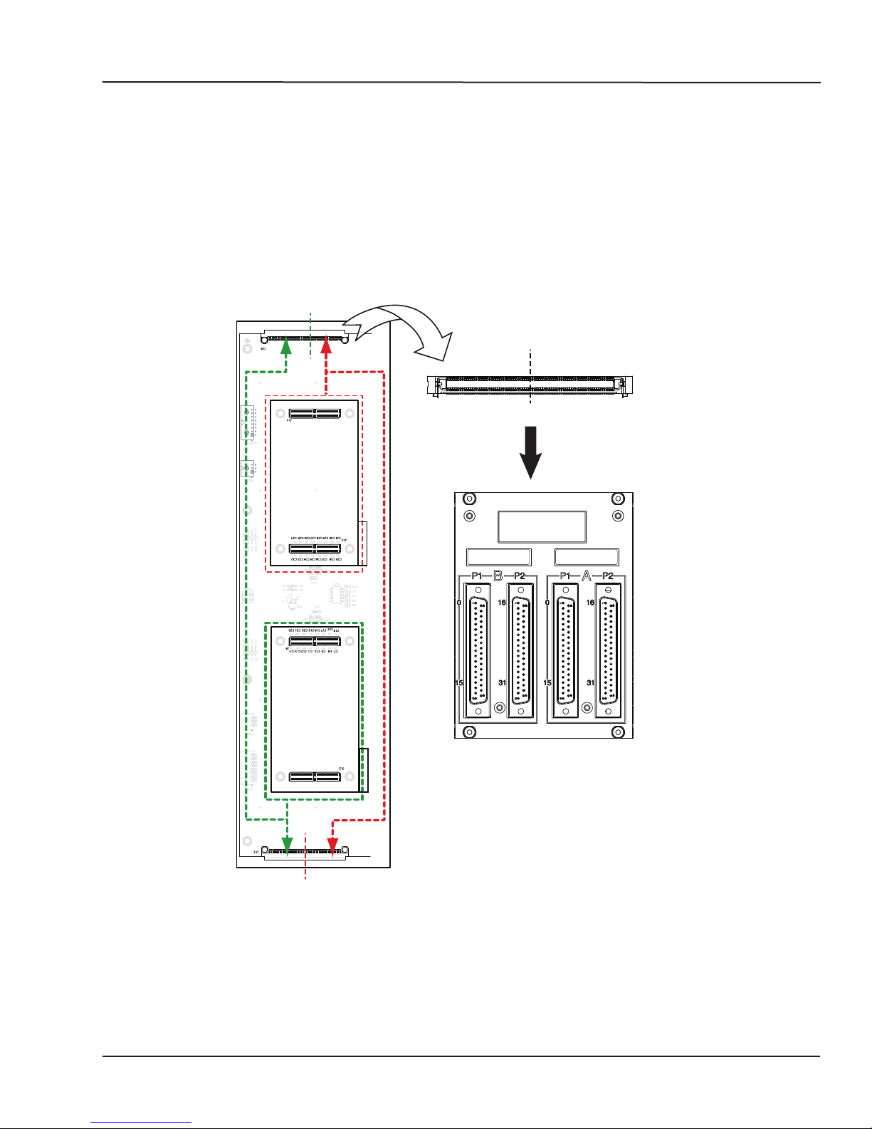
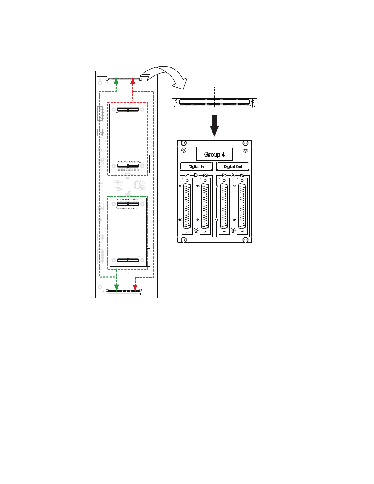
Each pair of mezzanines (A & B) is linked to four female DB37 connectors (I/Os) on the back of the
chassis:
The first two connectors (left to right) represent channels from Group B, which are linked to the
conditioned channels from the back mezzanine. The last two connectors (left to right) represent
channels from Group A, which are linked to the conditioned channels from the front mezzanine.
ANALOG MEZZANINES
OP5600 Rear (DB37)
(top view)
GROUP 1A
GROUP 1B
GROUP1B
GROUP 1B
Connector rear view
DB37 connector panel
GROUP 1A
Group 4
GROUP 1A
OP5600 Front (RJ45)
If the front mezzanine is an analog module (DAC or ADC), the 16 channels are on connector A and
connector B does not carry any signals.
If the back mezzanine is an analog module (DAC or ADC), the 16 channels are on connector C.
Connector D does not carry any signals.
15 OPAL-RT Technologies OP5600/OP5650 User Manual
GROUP1A
NOT USED
channels 0-15
GROUP 1B
channels 0-15
Figure 6: DB37 connection to mezzanines
NOT USED
Page 16
OP5600 Series/OP5650 Simulator
DB37F Connections
OP5600 Rear (DB37)
DIGITAL MEZZANINES
(top view)
GROUP 1A
GROUP 1B
GROUP1B
GROUP 1B
Connector rear view
GROUP 1A
GROUP1A
GROUP 1A
OP5600 Front (RJ45)
.
channels 0-15
GROUP 1B
channels 0-15
channels 16-31
channels 16-31
Figure 7: DB37 connection to mezzanines
If the front mezzanine is a digital module (Din or Dout), the first 16 channels (00 to 15) are on the first
connector and the next 16 channels (16 to 31) are on the second connector.
If the back mezzanine is a digital module (Din or Dout), the first 16 channels (00 to 15) are on the first
connector and the next 16 channels (16 to 31) are on the second connector.
All signals are represented by a positive-negative pair that are always available on the connector pins,
for example: for channel 08 : (08+, -08)
INTERFACE:
• For a single-ended output, the negative conductor is connected to Ground.
• For a differential output, the positive and negative signals are on the connector.
• For a differential input, the connection must be between the positive/negative pair.
• If the input is singled-ended, user’s ground must be connected to the negative side of the pair.
OP5600/OP5650 User Manual OPAL-RT Technologies 16
Page 17
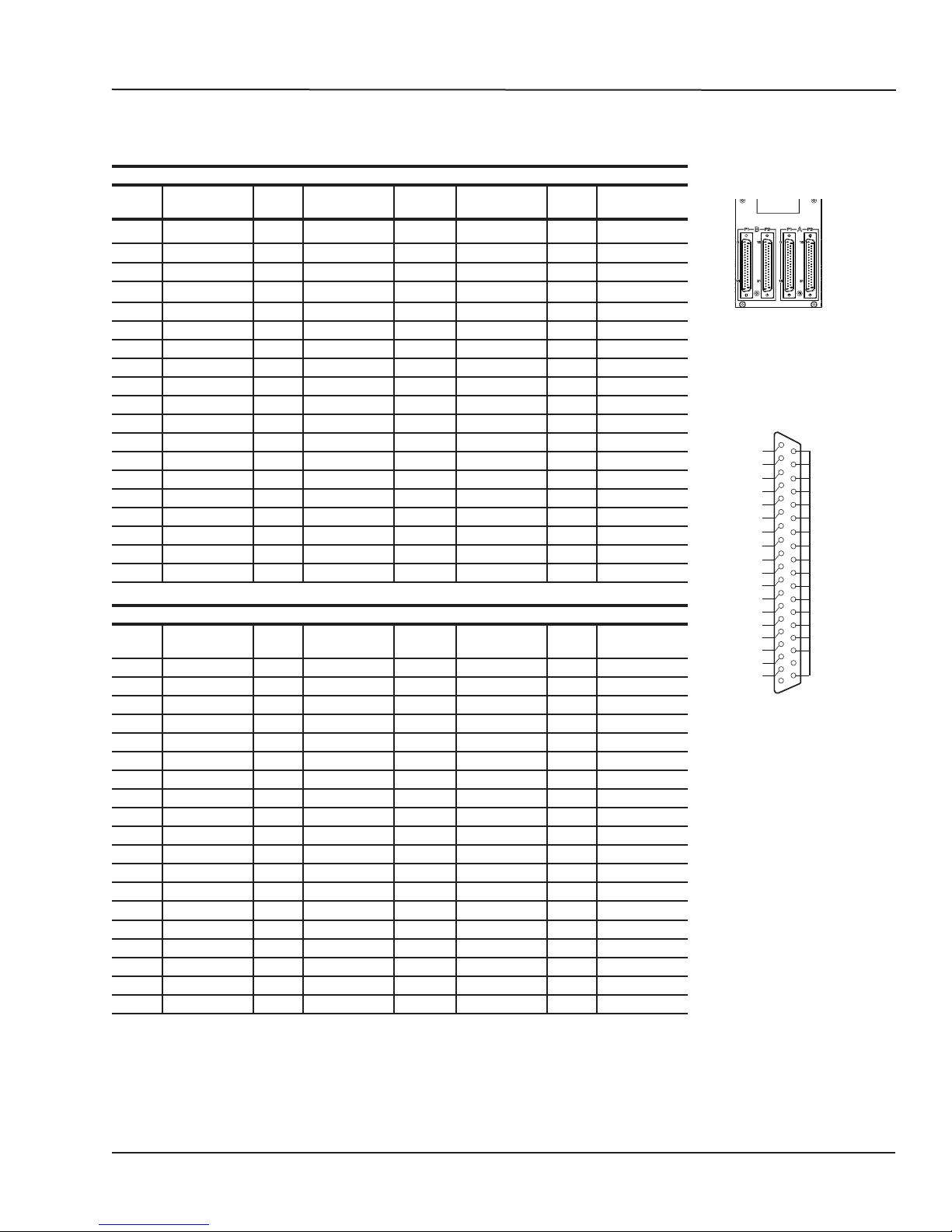
OP5650 DB37 PIN ASSIGNMENTS
DB37 connector panel silkscreen
Connector A Ch. 0-15 Connector A Ch. 16-31
DB37
Module pin
assignment
DB37
Module pin
assignment
DB37
Module pin
assignment
1 +CH00 20 -CH00 1 +CH16 20 -CH16
2 +CH01 21 -CH01 2 +CH17 21 -CH17
3 +CH02 22 -CH02 3 +CH08 22 -CH18
4 +CH03 23 -CH03 4 +CH19 23 -CH19
5 +CH04 24 -CH04 5 +CH20 24 -CH20
6 +CH05 25 -CH05 6 +CH21 25 -CH21
7 +CH06 26 -CH06 7 +CH22 26 -CH22
7 +CH07 27 -CH07 7 +CH23 27 -CH23
9 +CH08 28 -CH08 9 +CH24 28 -CH24
10 +CH09 29 -CH09 10 +CH25 29 -CH25
11 +CH10 30 -CH10 11 +CH26 30 -CH26
12 +CH11 31 -CH11 12 +CH27 31 -CH27
13 +CH12 32 -CH12 13 +CH28 32 -CH28
14 +CH13 33 -CH13 14 +CH29 33 -CH29
15 +CH14 34 -CH14 15 +CH30 34 -CH30
16 +CH15 35 -CH15 16 +CH31 35 -CH31
17 36 17 36
18 Vuser 1 A 37 Vrtn 1 A 18 Vuser 2 A 37 Vrtn 2 A
19 19
Connector B Ch. 0-15 Connector B Ch. 16-31
DB37
Module pin
assignment
DB37
Module pin
assignment
DB37
Module pin
assignment
1 +CH00 20 -CH00 1 +CH16 20 -CH16
2 +CH01 21 -CH01 2 +CH17 21 -CH17
3 +CH02 22 -CH02 3 +CH08 22 -CH18
4 +CH03 23 -CH03 4 +CH19 23 -CH19
5 +CH04 24 -CH04 5 +CH20 24 -CH20
6 +CH05 25 -CH05 6 +CH21 25 -CH21
7 +CH06 26 -CH06 7 +CH22 26 -CH22
7 +CH07 27 -CH07 7 +CH23 27 -CH23
9 +CH08 28 -CH08 9 +CH24 28 -CH24
10 +CH09 29 -CH09 10 +CH25 29 -CH25
11 +CH10 30 -CH10 11 +CH26 30 -CH26
12 +CH11 31 -CH11 12 +CH27 31 -CH27
13 +CH12 32 -CH12 13 +CH28 32 -CH28
14 +CH13 33 -CH13 14 +CH29 33 -CH29
15 +CH14 34 -CH14 15 +CH30 34 -CH30
16 +CH15 35 -CH15 16 +CH31 35 -CH31
17 36 17 36
18 Vuser 1 B 37 Vrtn 1 B 18 Vuser 2 B 37 Vrtn 2 B
19 19
Table 1: Pin Assignments
DB37
DB37
Module pin
assignment
Module pin
assignment
OP5600 Series/OP5650 Simulator
OP5650 DB37 Pin Assignments
1
20
00+
01+
02+
03+
04+
05+
06+
07+
08+
09+
10+
11+
12+
13+
14+
15+
Vuser
-00
-01
-02
-03
-04
-05
-06
-07
-08
-09
-10
-11
-12
-13
-14
-15
Vrtn
37
19
17 OPAL-RT Technologies OP5600/OP5650 User Manual
Page 18
OP5600 Series/OP5650 Simulator
RJ45 connections
RJ45 CONNECTIONS
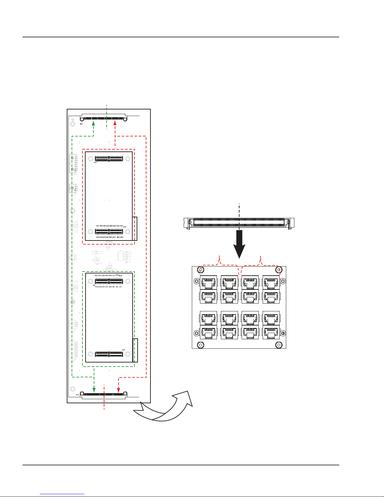
Each RJ45 monitoring panel on the front of the OP5650 simulator connects to front and back
mezzanines. The following images illustrate how the mezzanines are linked to the connectors.
OP5600 Rear (DB37)
GROUP1A
GROUP1B
GROUP1B
Top View
GROUP1A
GROUP1A
GROUP1B
GROUP1B
GROUP1A
OP5600 Front (RJ45)
GROUP1B
Figure 8: RJ45 connection to mezzanines
GROUP1A
channels 0-15
channels 0-15
ANALOG: NOT USED
Digital Channels 16-31
ANALOG: NOT USED
Digital Channels 16-31
OP5600/OP5650 User Manual OPAL-RT Technologies 18
Page 19
OP5600 Series/OP5650 Simulator
RJ45 channel Assignments
RJ45 CHANNEL ASSIGNMENTS
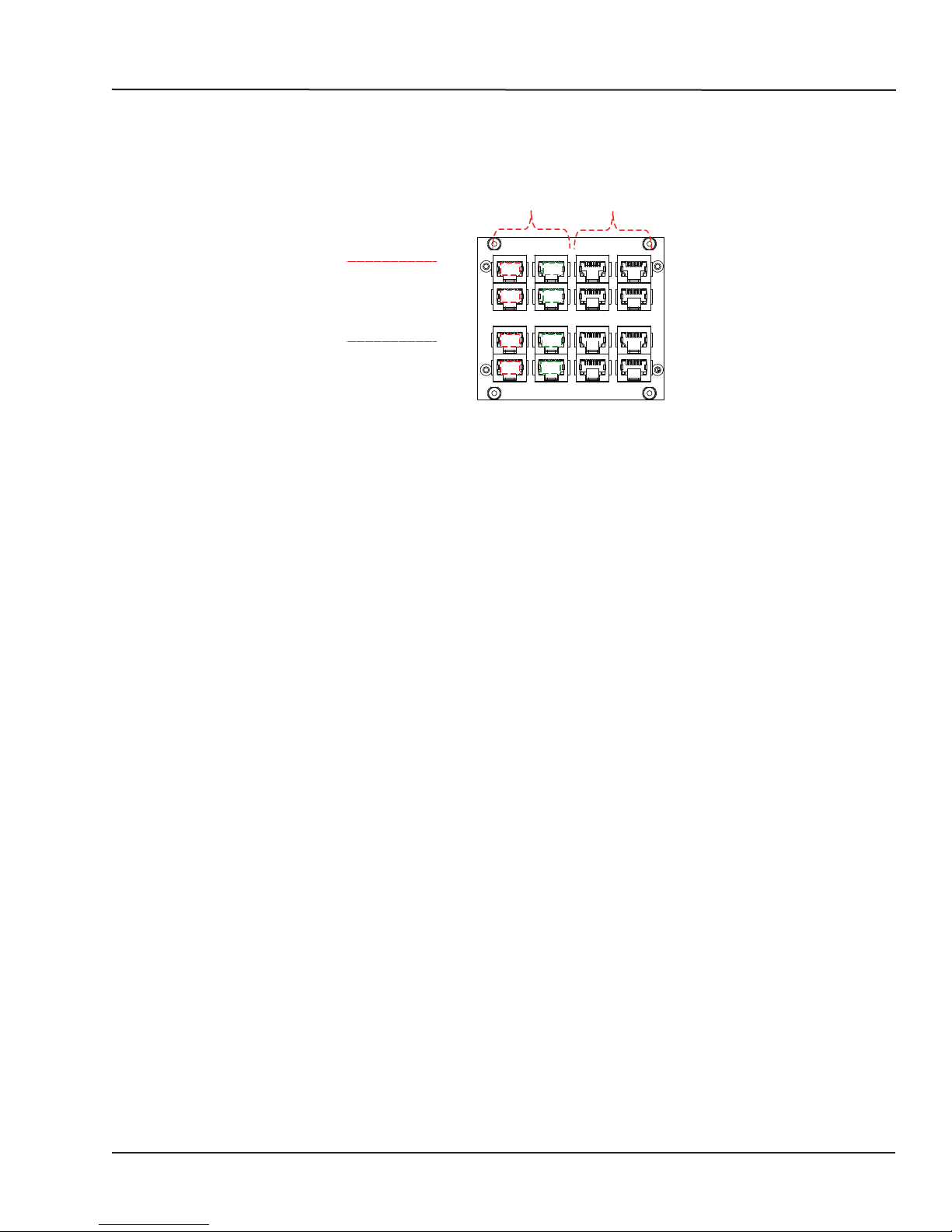
Each mezzanine is assigned two columns of RJ45 connectors. Each column represents a series of
channels, divided into 4 channels per jack, as shown in Figure 11.
SLOT xA
Column 1:
Channels 0-3
Channels 4-7
Channels 8-11
Channels 12-15
Column 2:
Channels 16-19
Channels 20-23
Channels 24-27
Channels 28-31
0-3
4-7
8-11
12-15
16-19
20-23
24-27
28-31
Analog boards use only channels 0-15
Digital boards use channels 0-31
Figure 9: RJ45 channel assignments
SLOT xB
19 OPAL-RT Technologies OP5600/OP5650 User Manual
Page 20
OP5600 Series/OP5650 Simulator
RJ45 channel Assignments
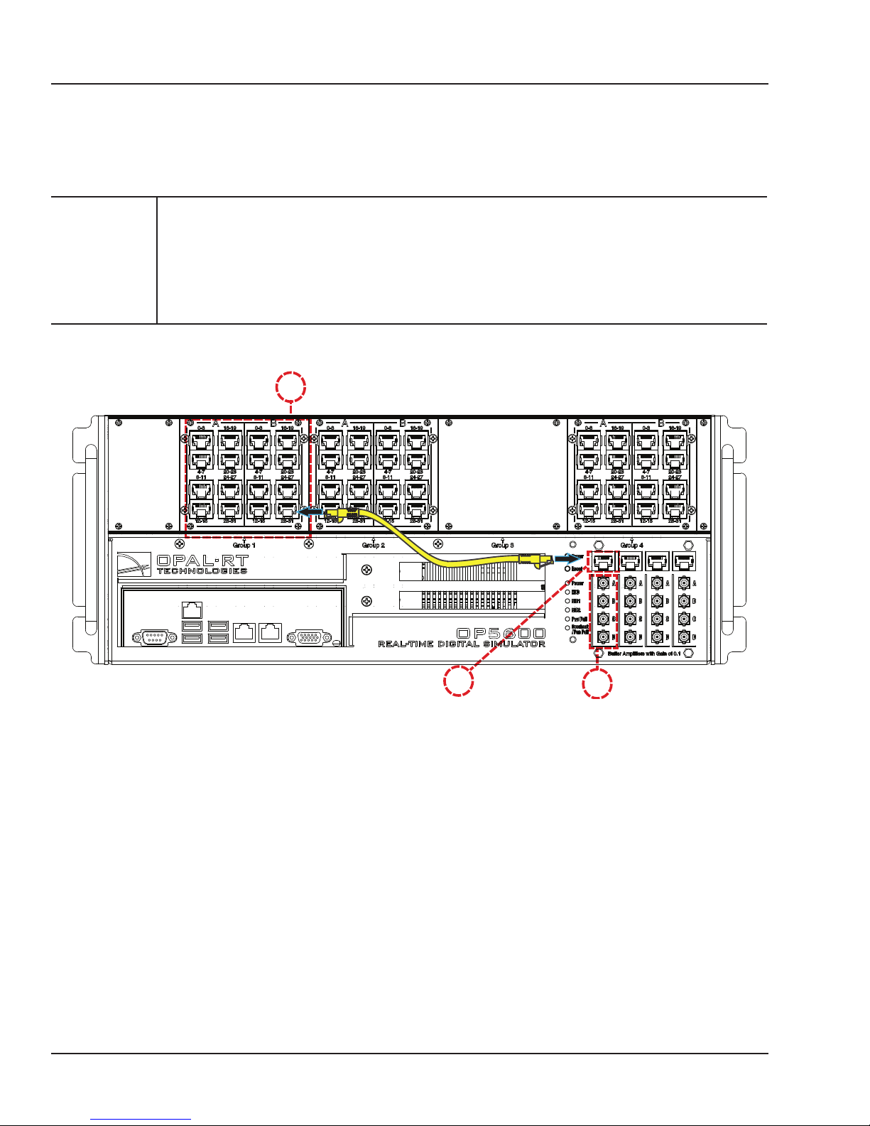
connecting monitoring devices
The OP5650 simulator offers quick, single-ended connections, through RJ45 and mini BNC connectors,
to any monitoring device (i.e. oscilloscope, etc.). These mini-BNC jacks let you monitor 4 channels
individually. Simply follow these instructions (as illustrated in Figure 12):
CAUTION
Only connect RJ45 cables from upper section (A) monitoring jacks to lower section
monitoring panel (B, as shown). Connecting any other cable or device may result in
damage to the equipment.
The network cable must only be connected to the standard computer connector network
jack (see page 15). DO NOT connect the network cable in any jack other than the jack
intended for that purpose.
A
B
Figure 10: How to connect cables for monitoring
1. Connect one end of the RJ45 cable to the desired channels (A). See Figure 11 for RJ45 connector
pinouts
2. Connect the other end of the RJ45 cable to the monitoring connector (B)
3. Connect a mini-BNC cable to each BNC jack (C) and connect the other end of the cable to the
desired monitoring device. The mini-BNC jacks each connect to one of the 4 channels of the RJ45
Connector (A). In the example shown in Figure 8, the RJ45 cable is connected to channels 28-31.
The mini-BNC cable jacks, identified as A, B, C, D, represent each channel in the following order;
A = channel 28,
B = channel 29,
C = channel 30
D = channel 31.
OP5600/OP5650 User Manual OPAL-RT Technologies 20
C
Page 21

OP5600 Series/OP5650 Simulator
Flat Carrier Specifications
SPECIFICATIONS
Product name OP5650 V3
Power supply Universal input and active power factor correction 650W continuous power
Power rating Input : 100-240VAC, 50-60Hz, 10A/5A
Input/output power -30V to +30V maximum
I/O connectors 4 panels of 4 DB37F connectors
Monitoring connectors 4 panels of RJ45 connectors
PC interface Standard PC connectors (monitor, keyboard, mouse and network)
PCI slots 3 PCIe slots (capable of accommodating up to 2 PCI boards)
Hard disk 512 Gb, 7200 rpm, SATA
Dimensions 48.3 x 45.7 x 17.8cm (19” x 18” x 7”)
Weight With PC: 9.07 - 15 Kg (20 lbs to 33 lbs)
Operating temperature 10 to 35 ºC (50 to 95ºF)
Storage temperature -55 to 85ºC (-67 to 185ºF)
Maximum rated ambient temperature 40Cº (104ºF)
Relative humidity 10 to 90% non-condensing
Maximum altitude 2000 m (6562 ft.)
DC to DC converters for analog voltage
Power: 600W
4 rear SFP ports
Fiber optic synchronization connectors (Tx/Rx)
Without PC: 4.54 - 5.9 Kg (10 lbs to 13 lbs)
FLAT CARRIER SPECIFICATIONS
Part Number 126-0591
Number of mezzanines 8 with Artix 7 configuration
Dimensions 38.1 x 38.1 cm (15 in x 15 in)
I/O connector 8 connectors, 160 positions each
Output power supply
(from DC-to-DC converters)
Input power supply +12 VDC @ 6 A
Operating temperature 10 to 40 ºC (50 to 104ºF)
Storage temperature -55 to 85ºC (-67 to 185ºF)
Relative humidity 10 to 90%, non condensing
Maximum altitude 2,000 m (6562 ft.)
±12 VDC @ 1.2 A (4 mezzanine A)
±12 VDC @ 1.2 A (4 mezzanine B)
±18 VDC @ 800 mA (4 mezzanine A)
±18 VDC @ 800 mA (4 mezzanine B)
+5 VDC @ 3A
21 OPAL-RT Technologies OP5600/OP5650 User Manual
Page 22

Limited Warranty
OP5650 User Manual OPAL-RT Technologies 22
Page 23

Limited Warranty
LIMITED WARRANTY
Limited Warranty
OPAL-RT Technologies Inc. warrants to the original purchaser and/or ultimate customer (“Purchaser”)
of OPAL-RT products (“Product”) that if any part thereof proves to be defective in material or
workmanship within one (1) year, such defective part will be repaired or replaced, free of charge,
at OPAL-RT Technologies’ discretion, if shipped prepaid to OPAL-RT Technologies Inc. at 1751
Richardson, suite 2525, Montreal, Quebec, Canada, H3K 3G6, in a package equal to or in the original
container. The Product will be returned freight prepaid and repaired or replaced if it is determined by
OPAL-RT Technologies Inc. that the part failed due to defective materials or workmanship. Otherwise,
the fees will be charged to the client (see article “Warranty Limitation and Exclusion”). The repair
or replacement of any such defective part shall be OPAL-RT Technologies’ sole and exclusive
responsibility and liability under this limited warranty.
Purchaser must request an RMA number before shipping any Product for repair:
1. Access the OPAL-RT website (www.opal-rt.com/support/ return-merchandise-authorization-rmarequest), click on support and select Return Merchandise (RMA).
2. Fill out the online form and submit. You will receive a notification with a thread-ID that will be used
for further exchange with support.
3. OPAL-RT’s Support department will evaluate the return and either issue an RMA number via email
using the same thread-ID.
- If the Product is returned for repair more than 12 months after purchase, the Purchaser is
responsible for the cost of repair. OPAL-RT will assess the repair and prepare a quote. The RMA
number will be sent with the quote.
4. Only when the Purchaser receives the RMA number, may they ship the Product, prepaid, to
OPAL-RT.
return PoLicy
The following fees will apply when customers return products for credit:
A full credit, less a 15% fee and less return fee will only be issued if the product is in perfect working
condition and if the product is returned within 1 month following the shipping date. If repairs are
required on the returned product, the cost of these repairs will be deducted from the credit to be
issued.
No credits will be issued beyond the one month period.
excLusions
If third party products are part of the Product, OPAL-RT will honor the original manufacturer’s warranty.
This limited warranty does not cover consumable items, such as batteries, or items subject to wear or
periodic replacement, including lamps, fuses or filter elements.
23 OPAL-RT Technologies OP5650 User Manual
Page 24

Limited Warranty
Warranty Limitation and excLusion
OPAL-RT Technologies will have no further obligation under this limited warranty. All warranty
obligations of OPAL-RT Technologies are void if the Product has been subject to abuse, misuse,
negligence, or accident or if the Purchaser fails to perform any of the duties set forth in this limited
warranty or if the Product has not been operated in accordance with instructions, or if the Product
serial number has been removed or altered.
discLaimer of unstated Warranties
The warranty printed above is the only warranty applicable to this purchase. All other warranties,
express or implied, including, but not limited to, the implied warranties of merchantability or fitness for a
particular purpose are hereby disclaimed.
Limitation of LiabiLity
It is understood and agreed that OPAL-RT Technologies’ liability, whether in contract, in tort, under
any warranty, in negligence or otherwise shall not exceed the amount of the purchase price paid by
the purchaser for the product and under no circumstances shall OPAL-RT Technologies be liable for
special, indirect, or consequential damages. The price stated for the product is a consideration limiting
OPAL-RT Technologies’ liability. No action, regardless of form, arising out of the transactions under this
warranty may be brought by the purchaser more than one year after the cause of actions has occurred.
OP5650 User Manual OPAL-RT Technologies 24
Page 25

Page 26

CONTACT
OPAL-RT Corporate Headquarters
1751 Richardson, Suite 2525
Montréal, Québec, Canada
H3K 1G6
Tel.: 514-935-2323
Toll free: 1-877-935-2323
Technical Services
www.opal-rt.com/support
:
Note
While every effort has been made to ensure
accuracy in this publication, no responsibility
can be accepted for errors or omissions. Data
may change, as well as legislation, and you are
strongly advised to obtain copies of the most
recently issued regulations, standards, and
guidelines.
This publication is not intended to form the
basis of a contract.
UM18-36249 RVN_1.0
12/2018
© OPAL-RT Technologies Inc.
 Loading...