

Opal-RT OP5650, OP5600 V3, OP5650-4, OP5650-32, OP5650-8 User Manual
...
OP5600 SERIES V3
Real-Time Digital Simulator
OP5650 User Manual
Artix 7
www.opal-rt.com

Published by
OPAL-RT Technologies, Inc. 1751 Richardson, suite 2525 Montreal, Quebec, Canada H3K 1G6
www.opal-rt.com
©2018 OPAL-RT Technologies, Inc. All rights reserved
Printed in Canada
SYMBOL DEFINITIONS
!
!
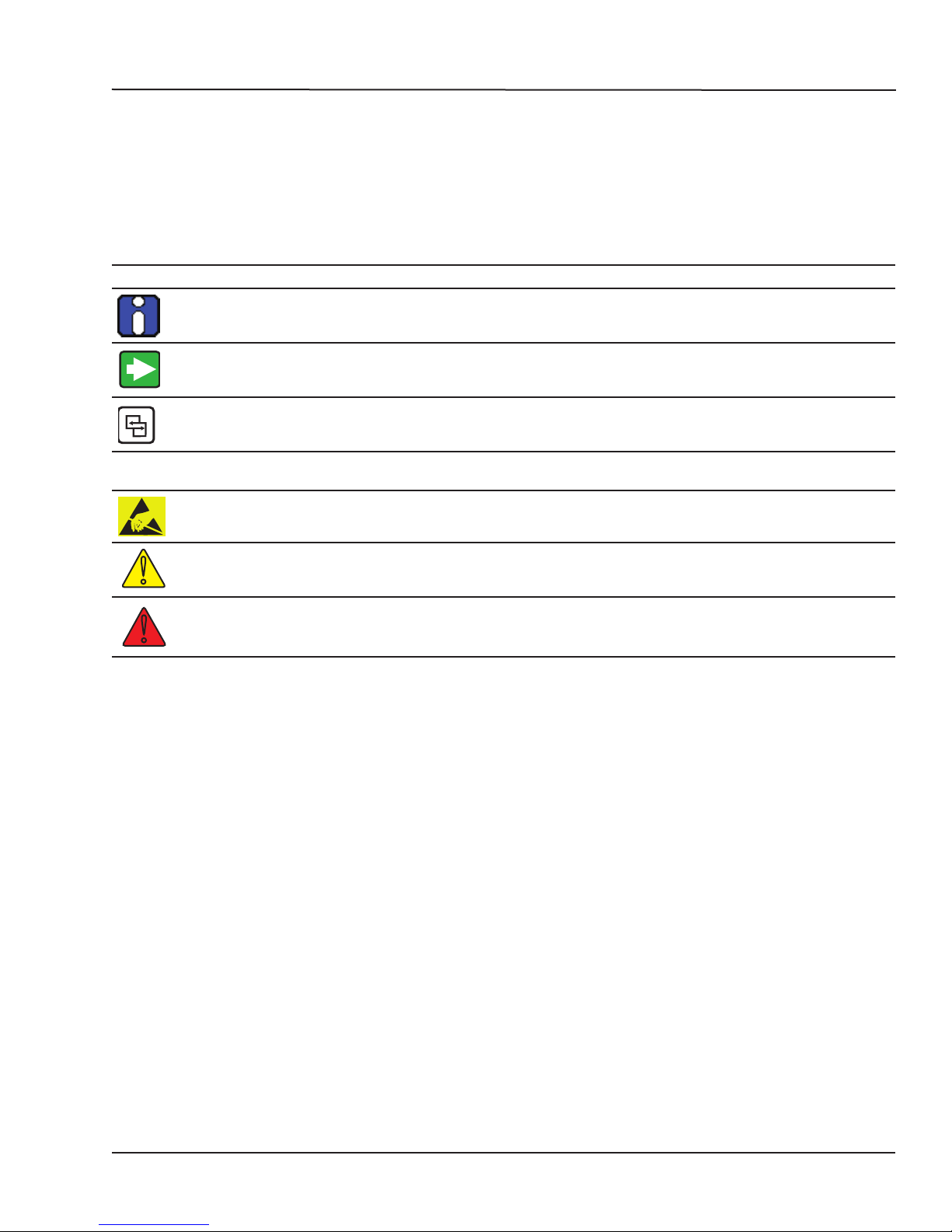
The following table lists the symbols used in this document to denote certain conditions:
Symbol Definition
ATTENTION: Identifies information that requires special consideration
TIP: Identifies advice or hints for the user, often in terms of performing a task
REFERENCE _ INTERNAL: Identifies an additional source of information within the bookset.
CAUTION
Indicates a situation which, if not avoided, may result in equipment or work (data) on the system being
damaged or lost, or may result in the inability to properly operate the process.
Indicates a situation where users must observe precautions for handling electrostatic sensitive devices.
CAUTION: Indicates a potentially hazardous situation which, if not avoided, may result in minor or
moderate injury. It may also be used to alert against unsafe practices.
WARNING: Indicates a potentially hazardous situation which, if not avoided, could result in serious injury or
death.
iii OPAL-RT Technologies OP5600/OP5650 User Manual


CONTENTS
RECEIVING AND VERIFICATION ........................................................................................................ 7
standard hardware .............................................................................................................................................. 7
OP5600 SERIES/OP5650 SIMULATOR .................................................................................................. 8
INTRODUCTION .................................................................................................................................. 8
SIMULATOR ARCHITECTURE ............................................................................................................ 9
configuration options .......................................................................................................................................... 9
Simulator Architecture Example ...................................................................................................................................... 9
INSTALLATION AND CONFIGURATION ............................................................................................ 10
HARDWARE CONFIGURATION ......................................................................................................... 11
back connectors ...............................................................................................................................................13
Connecting the Ground Screw ...................................................................................................................................... 14
DB37F CONNECTIONS ..................................................................................................................... 15
OP5650 DB37 PIN ASSIGNMENTS .................................................................................................. 17
RJ45 CONNECTIONS ........................................................................................................................ 18
RJ45 CHANNEL ASSIGNMENTS ..................................................................................................... 19
connecting monitoring devices...........................................................................................................................20
SPECIFICATIONS ............................................................................................................................ 21
FLAT CARRIER SPECIFICATIONS .................................................................................................... 21
LIMITED WARRANTY ............................................................................................................................ 23
Limited warranty .............................................................................................................................................. 23
return poLicy ...................................................................................................................................................23
excLusions ........................................................................................................................................................ 23
warranty Limitation and excLusion ....................................................................................................................24
discLaimer of unstated warranties ..................................................................................................................24
Limitation of LiabiLity ........................................................................................................................................24
5 OPAL-RT Technologies OP5600/OP5650 User Manual

OP5600/OP5650 User Manual OPAL-RT Technologies 6

Receiving and Verification
!
RECEIVING AND VERIFICATION
After opening the package, remove the equipment and components. Make sure that all the items
described in “standard hardware” are actually in the box and are undamaged.
standard hardware
The OP5650 real-time simulator includes the following basic hardware:
Item Description Part Number
OP5650 Simulator with Linux -based real-time O/S with PC
System Integration binder CD (documentation, models, licenses)software CD
Mini-BNC cables (4) 2 m (6 ft 6”) adapter cables for mini-BNC to BNC. 75 Ohms
RJ45 cables (5) 61cm (24”) RJ45 cables BLACK
Synchronization cable Plastic optical fiber patch cord 3M T00-0811
DB37M breakout board Provides extended space for connections T00-4069
Loopback Kit DB37 TestBoard
Power cable 1.83 m (6’) power cord, black (10A 125V)
Screws and rubber feet kit Extra if needed N/A
or OP5650-IO without CPU
Integration documents
simplex
61cm (24”) RJ45 cables WHITE
61cm (24”) RJ45 cables RED
61cm (24”) RJ45 cables GREEN
305cm (120”) RJ45 cable BLUE
Loopback Flat cable
Power cable
For Quick testing and Troubleshooting
Power Cord 6ft European (Schuko CEE7/7 to C13) - For Type E
and Type F
Power Cord 6ft Australia (AS3112 to C13) - Type I
Power Cord 6ft Brazil (NBR14136 to C13) - Type N
Power Cord 6ft China (GB2099 to C13) - Type I
Power Cord 6ft India (IS16A3 to C13) - Type D
Power Cord 6ft Switzerland (SEV1011 to C13) - Type J
Power Cord 6ft UK (BS1363 to C13) - Type G
N/A
T00-0719
T00-0723
T00-0724
T00-0725
T00-0726
T00-0817
126-0361
113-0737
113-0799
T00-0833
T00-0783
T00-0784
T00-0795
T00-0775
T00-0794
T00-1836
T00-0848
optional hardware
Item Description Part Number
MUSE transceiver Avago AFBR-57R5APZ T00-0315
MUSE cable LC-LC multimode 850nm optical fiber T00-0782
OPAL-RT strongly recommends the use of anti-static wrist straps whenever handling any electronic
device provided by OPAL-RT. Damage resulting from electrostatic charges will not be covered by the
manufacturer’s warranty.
Disconnect power before servicing
The OP5650 may be subjected to EMI when installed in proximity to other devices. Make sure to connect
the OP5650 ground to the rack to prevent any EMI related damage to the simulator.
7 OPAL-RT Technologies OP5600/OP5650 User Manual

OP5600 Series/OP5650 Simulator
Introduction
OP5600 SERIES/OP5650 SIMULATOR
INTRODUCTION
The OP5650 is a complete simulation system, that contains a powerful target computer, a
reconfigurable FPGA and signal conditioning for up to 256 I/Os. The design makes it easy to use with
standard connectors (DB37, RJ45, SFP and mini-BNC) without the need for input/output adaptors and
allows quick connections for monitoring I/O signals. It is designed to be used either as a desktop, shelf
top, or mounted in a standard 19’’ rack.
The front of the chassis provides access to the target computer’s standard connectors, and monitoring
interfaces and connectors, while the back of the chassis provides access to the I/O connectors, power
cable and main power switch.
Inside, the main housing is divided into two sections, each with a specific purpose:
In its standard configuration, the lower part of the chassis contains a powerful target computer that
can be added to a network of simulators or can act as a standalone. The target computer used to run
simulations built with OPAL-RT’s RT-LAB or HYPERSIM software simulation platform includes the
following features:
• ATX motherboard
• Linux-based real-time operating system
• Xeon E5 Intel CPU with 4, 8, 16 and 32 processor cores, up to 3.2GHz
• 10MB Cache Memory per 4 cores
• up to 32GB of DRAM,
• 512GB SSD disk,
• Space to install 2 PCI with risers, or 3 PCIe boards.
• Power consumption: 600W Max.
The upper section contains the high-speed FPGA and the conditioning modules for up to 256 I/Os. The
main features include:
• Xilinx Artix 7 FPGA 200T, programmable from the target computer via PCIe or MUlti-System
Expansion (MUSE). The FPGA is used to execute models designed with the OPAL-RT RT-XSG
tool, and manage the I/O lines. It exchanges data with the real-time simulations running on the
target computer CPUs via the PCIe link.
• Flat carrier capable of connecting any combination of up to 8 type B mezzanine boards.
OP5600/OP5650 User Manual OPAL-RT Technologies 8
 Loading...