

Page 1
©Copyright by Opale-Paramodels 2013 MAXV1.0EN
Page 1 sur 6
User’s guide
Please read carefully this manual before usine your equipment for the first time
Page 2
©Copyright by Opale-Paramodels 2013 MAXV1.0EN
Page 2 sur 6
Thanks for having chosen an Opale-Parmodels product. We truly believe this radio-controlled paraglider is going to
give you hours of enjoyment and will enable you to go through new outstanding piloting experiences. This user’s guide
content includes all the information you need to get your wing fly and to ensure you will take good care of it. A good
knowledge of your equipment will allow you to safely make the most of its performances for your greatest pleasure!
Thanks for giving this manual to the new owner in case you decided to sell you radio-controlled paraglider.
Best regards,
The Opale-Paramodels Team
Safety Information
You should be properly insured according to the country regulation you are using our equipment in. You hereby
accept the inherent risk of flying radio-controlled models. Using our equipment in a bad way may increase risks.
Neither Opale-Paramodels nor any other seller will be liable for any damage caused by any accident whatever the
circumstances are. The way our equipment is used is incumbent upon the final user, including towards the law.
Page 3
©Copyright by Opale-Paramodels 2013 MAXV1.0EN
Page 3 sur 6
Summary
1. Equipment necessary for the assembly ……………………….………………………………….…………………………………………….4
2. Mounting Servomotors and Speed Bar System (in option) ..……..….…………..……………………………………..………….4
3. Arms préparation …..…………………………………………………………………………..…………………………………………………………...4
4. Max dressing and installation on his harness……………….…………………………………………………………………………………5
5. Arms Settings.………………………………………………………………………………….………………………………………………..……………..6
6. Speed Bar System settings (in option)...…………………………………….…………………………………………………..………………6
Page 4
©Copyright by Opale-Paramodels 2013 MAXV1.0EN
Page 4 sur 6
1 Equipment necessary for the assembly
To assembly Max and use all its technical possibilites, you will require :
- Drilling machine
- 2 mm drill
- Hot glue pistol
- Phillips screwdrivers
- 2 servomotors 10kg/cm
- 2 servomotors de 6.4kg/cm
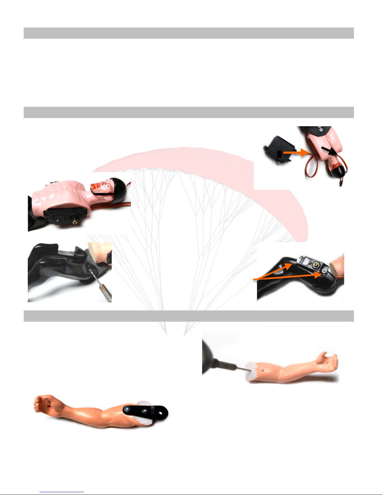
2 Mounting Servomotors and Speed Bar System (optional)
Please take 2 servomotors 10 kg.cm ( standart size : 40*20 mm).
Insert the cable of the servo in the upper body and get out on the opening provided for this purpose (step 1).
Then slide the servo into the upper body. If it’s difficult to insert the servo, it’s justified by a need to reduce
the gap between the servo and bust. (step 2)
Do the same with the other servo.
Add hot glue or époxy between the two servomotors if it’s necessary.
Mounting of actuators required to Speed Bar System (in option)
Enlarge the pre-drilled holes with a 2mm drill. (left photo)
Then attach directly the servos with philips screws. (right photo)
3. Arms preparation
To use the pilot’s arms, enlarge the pre-drilled holes with the 2mm drill.
Please take your servo arm and two Phillips screws.
Attach the servo arm to the arm. Pay attention to the mounting direction of
the servo arm.
Do the same for the second arm.
Page 5
©Copyright by Opale-Paramodels 2013 MAXV1.0EN
Page 5 sur 6
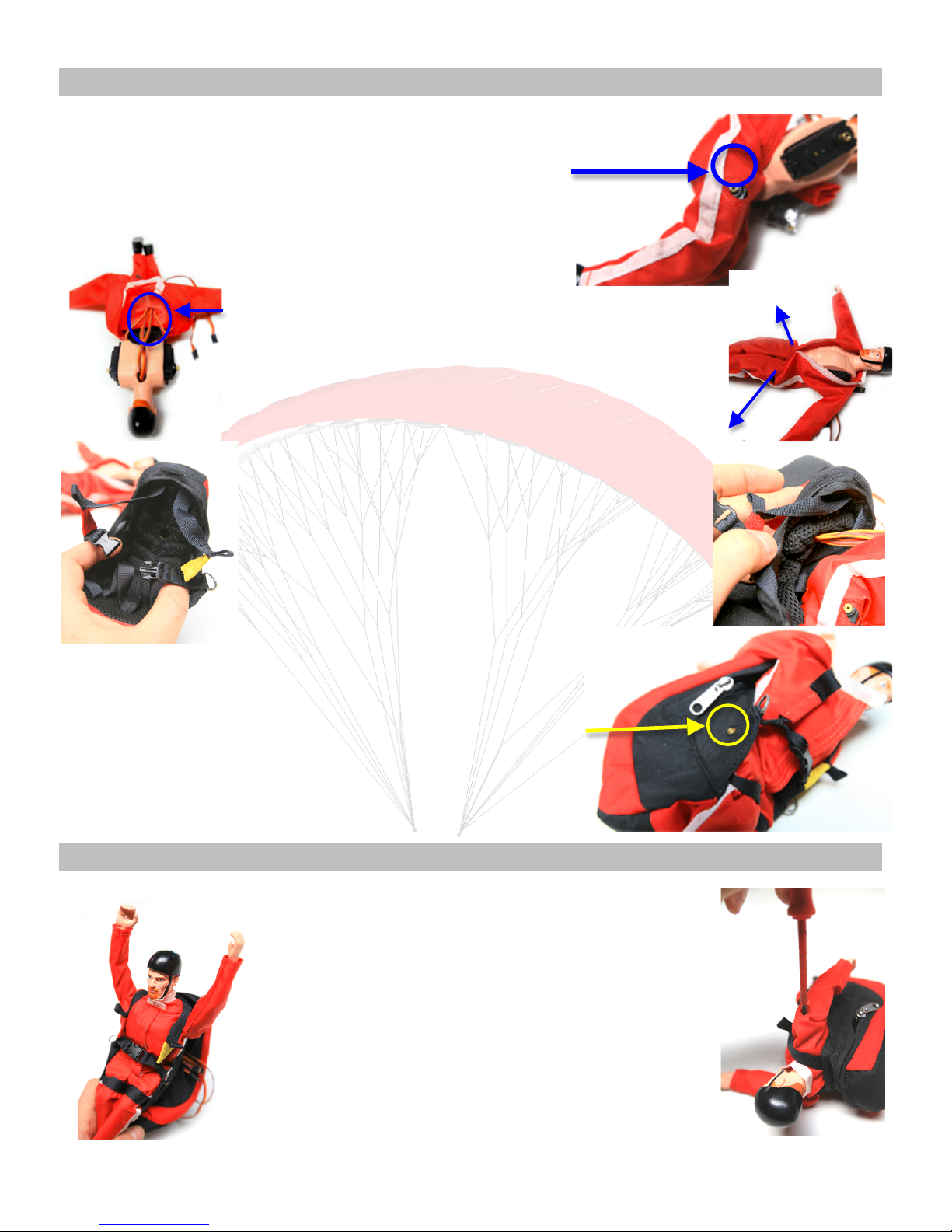
4. Max Clothing and harness settings
Clothe the pilot, pulling the combinaison by legs.
Make sure that the servo gear is going through the hole which is on the clothing.
If you have not selected this option, please go to the next step.
Then go all the cables to the back hole of the combination, then go back there until shoulders.
Insert the right and left arm on their sleeve before closing the combination.
Take the harness and open the rear compartment ;
Slide the legs throught the straps and put the cables on the hole (back of the harness).
Now, you’ve connections in the rear compartment.
Be careful to highlight the servos gear of the Speed Bar System by the slot on the side of the
harness. If you did not choose this option, please go to the next step.
5. Arms settings
Push the servo arm on the upper position and place the servo in high mechanical
position.
If your arm is not in vertical position when the servo is in High mechanical position,
readjust to the desired positions (left picture).
Then, picl up the screw to come fix it.
You can do the same operation for the other arm.
Put the servos on, you arms should be at the same height.
If it is not, do not hesitate to move your arms a few notches so that they will be both in
front of one another.
Page 6
©Copyright by Opale-Paramodels 2013 MAXV1.0EN
Page 6 sur 6
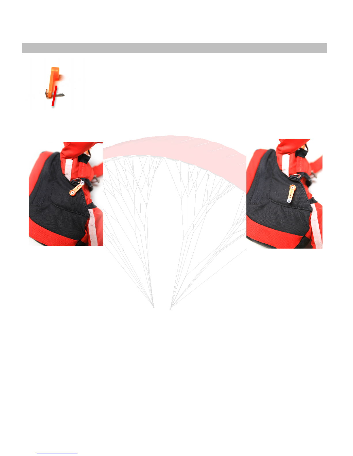
6. Speed Bar System settings (in option)
Install a screw at the end of the servo arm. Cut the excès to the next front hanger attach necessary to use the speed bar
system.
Put your servos on and fit the servos arms. In neutral position, the servo arms should be horizontal (same direction as the leg).
We recommend using a switch two or three positions.
In position 1, you are not accelerated
In position 2, you are accelerated. This mode is the fastest flight.
An intermediate position half-movement is possible.
Remember once the final adjustement to tighten the servo arm.
Position 1
(Unaccelerated)
Cut here
Position 2
(accelerated)
 Loading...