

Page 1
WorkBee CNC
Full Kit Assembly Instructions
Page 2

Page 3

WorkBee CNC 1
Table of Contents
1.0 Getting Started 3
1.1 About The Kit 4
1.2 Check Product Contents 4
1.3 Tools Required 4
1.4 Notes on Assembly 4
2.0 Drag Chains Assembly 6
2.1 Y-Axis 7
2.1.1 Y-Axis Fixed End Assembly ........................................................... 7
2.1.2 Y-Axis Fixed End Mounting............................................................ 8
2.1.3 Y-Axis Moving End Assembly......................................................... 9
2.1.4 Y-Axis Moving End Mounting ....................................................... 10
2.1.5 Y-Drag-Chain............................................................................ 11
2.2 X-Axis 12
2.2.1 X-Axis Fixed End Mounting ......................................................... 12
2.2.2 X-Axis Moving End Assembly ...................................................... 13
2.2.3 X-Axis Moving End Mounting....................................................... 14
2.2.4 X-Drag-Chain ........................................................................... 15
3.0 Power Supply Assembly 16
3.1 Output 17
3.1.1 Securing XT60-Male Outputs ...................................................... 17
3.1.2 Inserting LED-Volt-Meter ............................................................ 18
3.2 Input 19
3.2.1 IEC-Inlet Wires ......................................................................... 19
3.2.2 Attaching IEC-Inlet.................................................................... 20
3.3 Connecting PSU-Cover 21
3.3.1 Connecting Wires ...................................................................... 21
3.3.2 Attaching PSU-Cover ................................................................. 23
3.3.3 Testing .................................................................................... 24
4.0 Limit Switches & Wire Routing 25
4.1 Limit Switches 26
4.1.2 Z-Axis Limit Switch.................................................................... 28
4.2 Wire Routing 29
4.2.2 Screw Driven - Gantry Wire Routing ............................................ 30
4.2.3 Belt Driven - Gantry Wire Routing ............................................... 31
4.2.4 Screw Driven - Y-Axis Wire Routing - Part 1 .................................. 32
4.2.5 Screw Driven - Y-Axis Wire Routing - Part 2 .................................. 33
4.2.6 Belt Driven - Y-Axis Wire Routing ................................................ 34
5.0 CNC xPro Assembly 35
5.0.1 Terminal-Block Attachment......................................................... 36
5.0.2 Fan Mount Assembly.................................................................. 37
5.0.3 Attaching The CNC-xPro ............................................................. 38
5.0.4 Fans Wiring.............................................................................. 39
5.0.5 Mounting the CNC-xPro Assembly................................................ 40
6.0 Wiring & Commissioning 42
6.1 CNC-xPro Wiring 43
6.2 Software & Machine Settings 44
6.2.1 Installing Universal G-Code Sender (UGS) .................................... 44
6.2.2 Configuring The Firmware .......................................................... 45
Page 4

WorkBee CNC 2
6.3 Testing 46
6.4 Wire Tidying 48
6.5 Complete 49
7.0 Appendix 51
7.1 Appendix A - Kit Contents 52
8.0 Appendix B 59
8.1 Recommended GRBL Settings 60
8.2 Invert Mask Table 63
9.0 Appendix C 64
9.1 Common Trouble Shooting Questions 65
Page 5

WorkBee CNC Getting Started 3
1.0 Getting
Started
Page 6

WorkBee CNC Getting Started 4
1.1 About The Kit
This manual is for the full kit version of the WorkBee CNC Machine. Ideally, this manual
should be started straight after completing the mechanical assembly. This manual will turn
the mechanical portion of the WorkBee into a working moving machine.
Our WorkBee CNC Machine has a very large community of users, who can mostly be found
at http://openbuilds.com. It is free to sign up to this community and it will allow you to
share your builds, interact with other members, and download useful community created
resources. We have a specific build thread for the WorkBee, and we would love to see your
machines and what you make with them: https://openbuilds.com/builds/workbee-cncmachine.5626/.
1.2 Check Product Contents
When you receive your kit, the first thing you should do is check the contents against the
list in Appendix A. The majority of the parts will be separated into boxes that correspond
to the subsections in this manual. Additional spare small parts will be included. If anything
is missing or damaged (or if you have any other problems) please contact us at
[email protected] and we will aim to resolve the issue as quickly as possible.
1.3 Tools Required
• The list below shows the main tools that will be required to complete this build:
• 2.5mm Allen Key
• 3.0mm Allen Key
• 4.0mm Allen Key
• 5.5mm Spanner
• 7.0mm Spanner
• 8.0mm Spanner
• Hammer
• Selection of Philips Screwdrivers
• Selection of Flathead Screwdrivers
• Tweezers
• Wire Cutters/Strippers
1.4 Notes on Assembly
This manual has been written for the construction of a 750 x 750mm screw driven version
of the WorkBee. If you have a different version everything is exactly the same, with the
exception of longer V-Slot extrusions and wire routing.
The assembly has been split into 5 sections: Drag Chains Assembly, Power Supply
Assembly, Limit Switches & Wire Routing, CNC xPro Assembly, Wiring & Commissioning.
To make locating parts quicker, leave the parts in the boxes they came in when carrying
out the build.
Page 7

WorkBee CNC Getting Started 5
It is recommended that you read through the whole manual before beginning the build in
order to get a full picture of the assembly process. Before beginning each step, make
sure you have studied the diagram and have the required parts in front of you. A PDF
version of the manual is available on our website and this will allow you to zoom in on the
diagrams if needed.
Be very careful to not over tighten the nuts and bolts on the plastic parts, otherwise they
may crack. Everything should easily fit together, and so if it isn’t, take a step back and
re-read the instructions.
Assembly of this kit involves the use of electricity and therefore you should take appropriate precautions to ensure you are assembling the kit in a safe manner. When following
wiring diagrams, double check that everything is connected correctly. Before carrying out
any work on the electrics make sure that the machine is switched off.
The polarity is indicated by the color of the wire, not by the color of the connectors at each
end. For the AC IEC input, the live wire is brown, neutral blue, and earth is green and yellow. For the DC Wiring of the machine a positive wire is red, negative is black, and earth
is green and yellow.
Page 8

WorkBee CNC Drag Chains Assembly 6
2.0 Drag
Chains
Assembly
Page 9
WorkBee CNC Drag Chains Assembly 7
2.1 Y-Axis
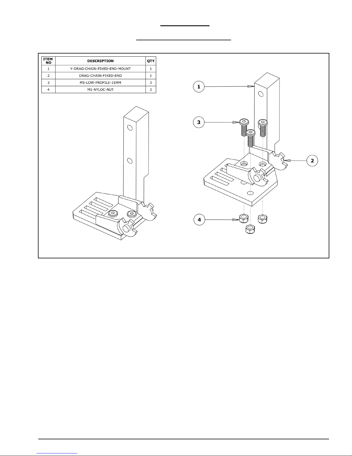
2.1.1 Y-Axis Fixed End Assembly
A. Attach a Drag-Chain-Fixed-End to the Y-Drag-Chain-Fixed-End-Mount in the orienta-
tion shown above, using 3 x M5-Low-Profile-15mm bolts and 3 x M5-Nyloc-Nut’s.
Page 10
WorkBee CNC Drag Chains Assembly 8
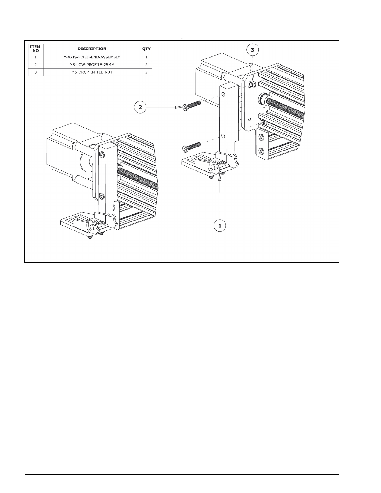
2.1.2 Y-Axis Fixed End Mounting
A. Position the Y-Axis-Fixed-End-Assembly to the back left corner of the WorkBee. It
should be flush with the end of the C-Beam-750mm. Secure it using 2 x M5-Low-Profile-25mm bolts and 2 x M5-Drop-In-Tee-Nuts.
Page 11
WorkBee CNC Drag Chains Assembly 9
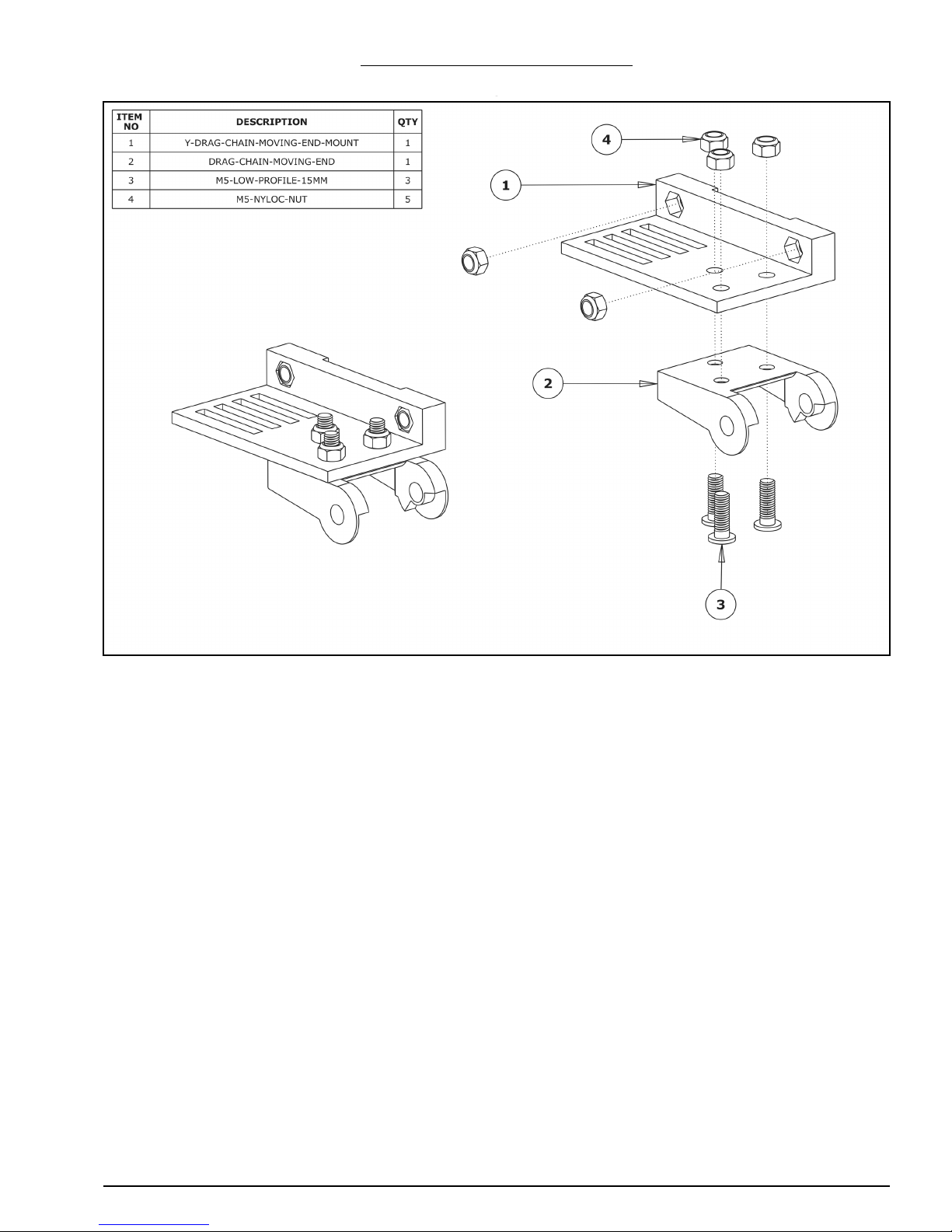
2.1.3 Y-Axis Moving End Assembly
A. Insert 2 x M5-Nyloc-Nuts into the insets on the Y-Drag-Chain-Moving-End-Mount.
They are a snug fit, so may require a light tap with a hammer.
B. Attach a Drag-Chain-Moving-End to the Y-Drag-Chain-Moving-End-Mount in the orien-
tation shown above using 3 x M5-Low-Profile-15mm bolts and 3 x M5-Nyloc-Nuts.
Page 12
WorkBee CNC Drag Chains Assembly 10
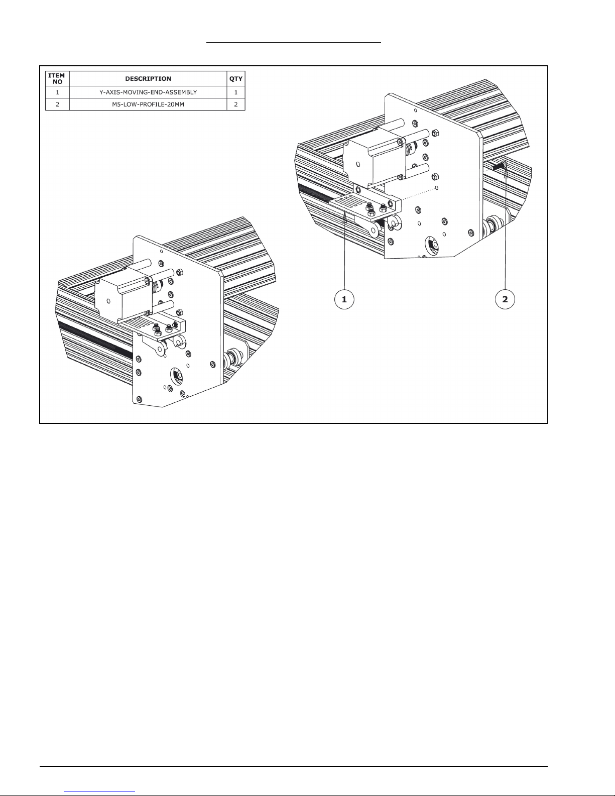
2.1.4 Y-Axis Moving End Mounting
A. Secure the Y-Axis-Moving-End-Assembly using 2 x M5-Low-Profile-20mm bolts and
the 2 x M5-Nyloc-Nuts already inserted into Y-Drag-Chain-Moving-End-Mount.
Page 13
WorkBee CNC Drag Chains Assembly 11
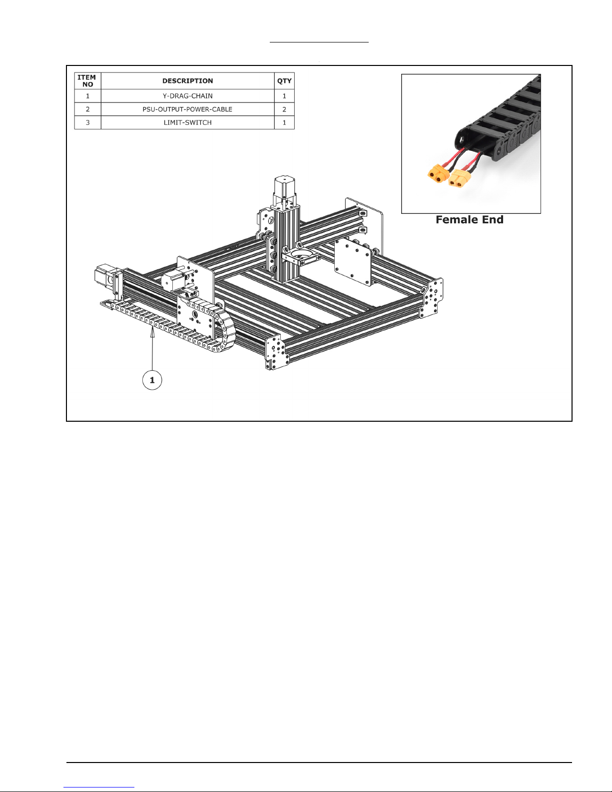
2.1.5 Y-Drag-Chain
A. Lay the Y-Drag-Chain flat on a table. Feed one of the PSU-Output-Power-Cables
through the whole length of the Y-Drag-Chain. Ensure that the end with the XT60Connector, is located at the female end of the Y-Drag-Chain (as shown above in the
‘Female End’ image). Repeat for a second PSU-Output-Cable. If the PSU-OutputPower-Cable gets snagged inside the Y-Drag-Chain, the tabs on the Y-Drag-Chain flip
open for access.
B. If you have a screw driven WorkBee only feed two stepper motor wires through the Y-
Drag-Chain. The end of the stepper motor wires with the black connector should be at
the female end of the Y-Drain-Chain - same as Step A. Further to this, one of the stepper motor cables will be considerably longer than the other three - this cable should
be one of the two which go inside the Y-Drag-Chain.
C. For all WorkBee Variants, feed the wires on a Limit-Switch, through the Y-Drag-Chain.
The switch portion of the Limit-Switch should be at the female end of the Y-DragChain.
D. Lay the Y-Drag-Chain flat along the left side of the WorkBee. The female end of the Y-
Drag-Chain should be at the back of the machine, and the male end at the front.
E. Attach the female end of the Y-Drag-Chain to the Drag-Chain-Fixed-End on the Y-Axis-
Fixed-End-Assembly. It will take some force to click it into the Drag-Chain-Fixed-End.
F. Bring the male end of the Y-Drag-Chain to the Y-Axis-Moving-End-Assembly and
attach it to the Drag-Chain-Moving-End. It will take some force to click it into the
Drag-Chain-Moving-End.
Page 14
WorkBee CNC Drag Chains Assembly 12
2.2 X-Axis
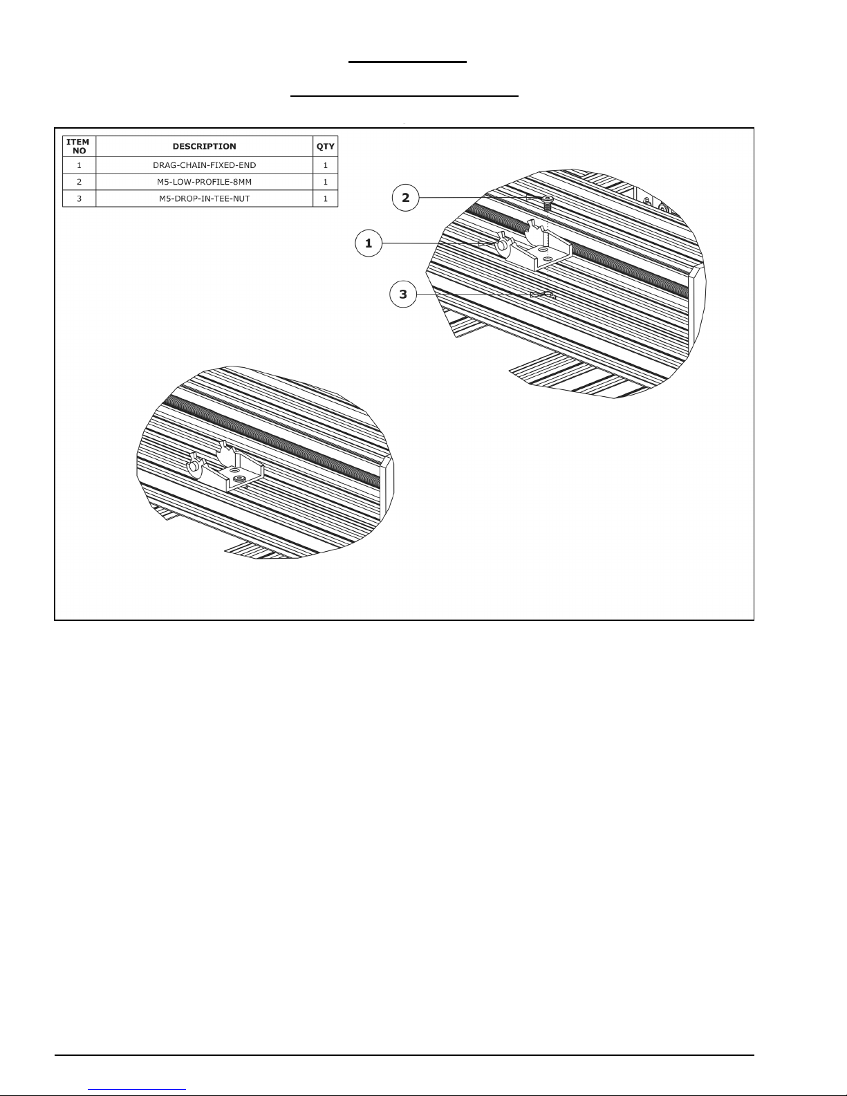
2.2.1 X-Axis Fixed End Mounting
A. Attach a Drag-Chain-Fixed-End to the V-Slot-2040-750mm using an M5-Low-Profile-
8mm and an M5-Drop-In-Tee-Nut. Ensure it is orientated as above; it should be
located 150mm from right hand end of the V-Slot-2040-750mm if looking from the
back. Ensure that it is parallel with the V-Slot-2040-750mm.
Page 15

WorkBee CNC Drag Chains Assembly 13
2.2.2 X-Axis Moving End Assembly
A. Attach a Drag-Chain-Moving-End to the X-Drag-Chain-Moving-End-Mount in the ori-
entation shown above using 3 x M5-Low-Profile-15mm bolts and 3 x M5-Nyloc-Nuts.
Page 16
WorkBee CNC Drag Chains Assembly 14
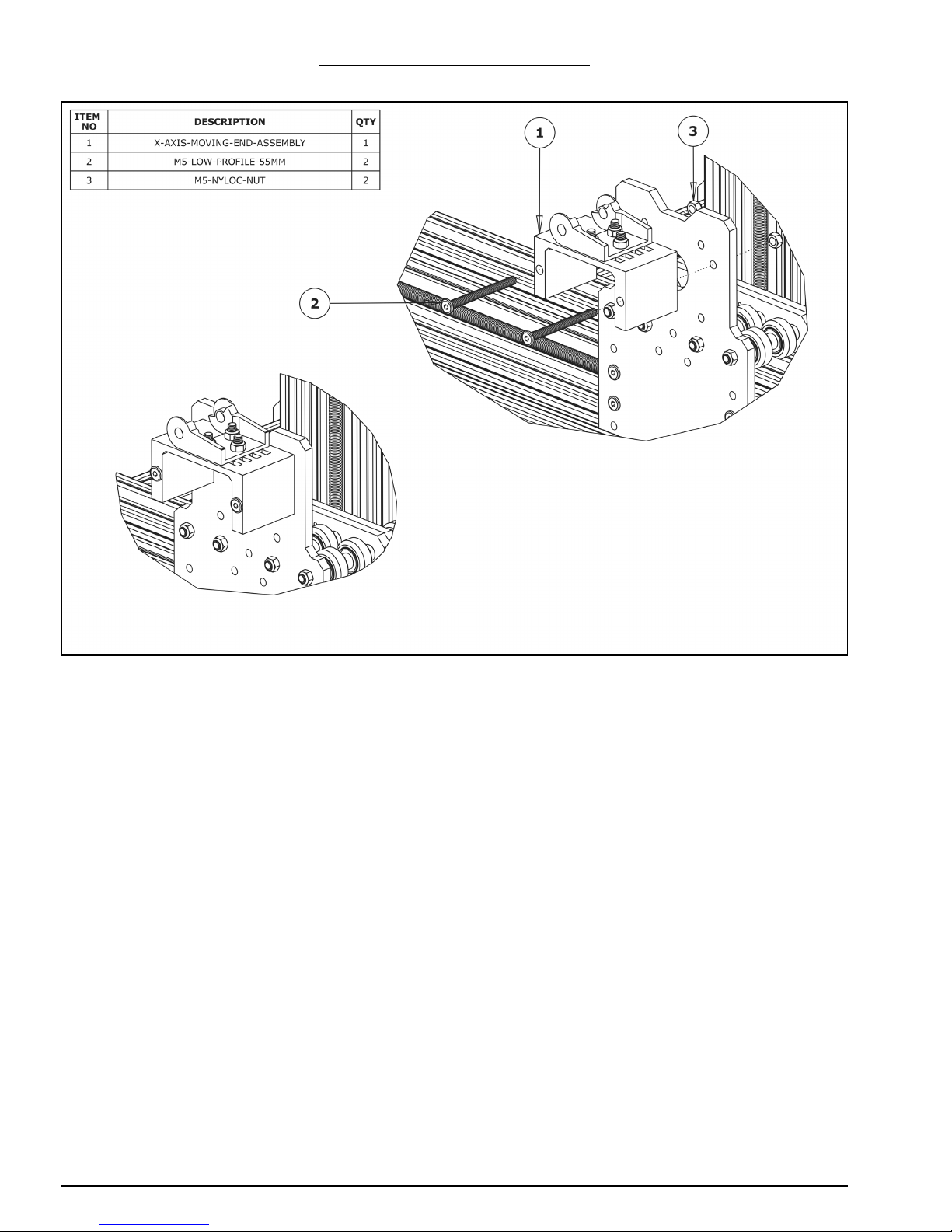
2.2.3 X-Axis Moving End Mounting
A. Secure the X-Axis-Moving-End-Assembly to the X-Plate-Back using 2 x M5-Low-Pro-
file-55mm bolts and 2 x M5-Nyloc-Nuts.
Page 17
WorkBee CNC Drag Chains Assembly 15
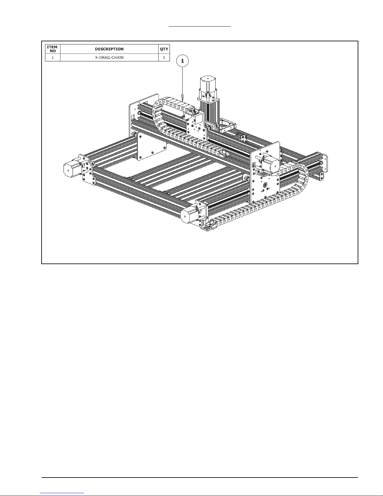
2.2.4 X-Drag-Chain
A. Like in Section 2.1.5 lay the X-Drag-Chain flat on a table. If you have a screw driven
WorkBee feed through one stepper motor wire. If you have a belt driven WorkBee feed
through two. The end of the stepper motor wires with the black connectors should be
at the male end of the X-Drag-Chain (opposite to Section 2.1.5).
B. Attach the female end of the X-Drag-Chain to the Drag-Chain-Fixed-End on the V-
Slot-2040-750mm. It will take some force to click it into the Drag-Chain-Fixed-End.
C. Bring the male end of the X-Drag-Chain up to the X-Axis-Moving-End-Assembly and
attach it to the Drag-Chain-Moving-End. It will take some force to click it into the
Drag-Chain-Moving-End.
Page 18

WorkBee CNC Power Supply Assembly 16
3.0 Power
Supply
Assembly
Page 19
WorkBee CNC Power Supply Assembly 17
3.1 Output
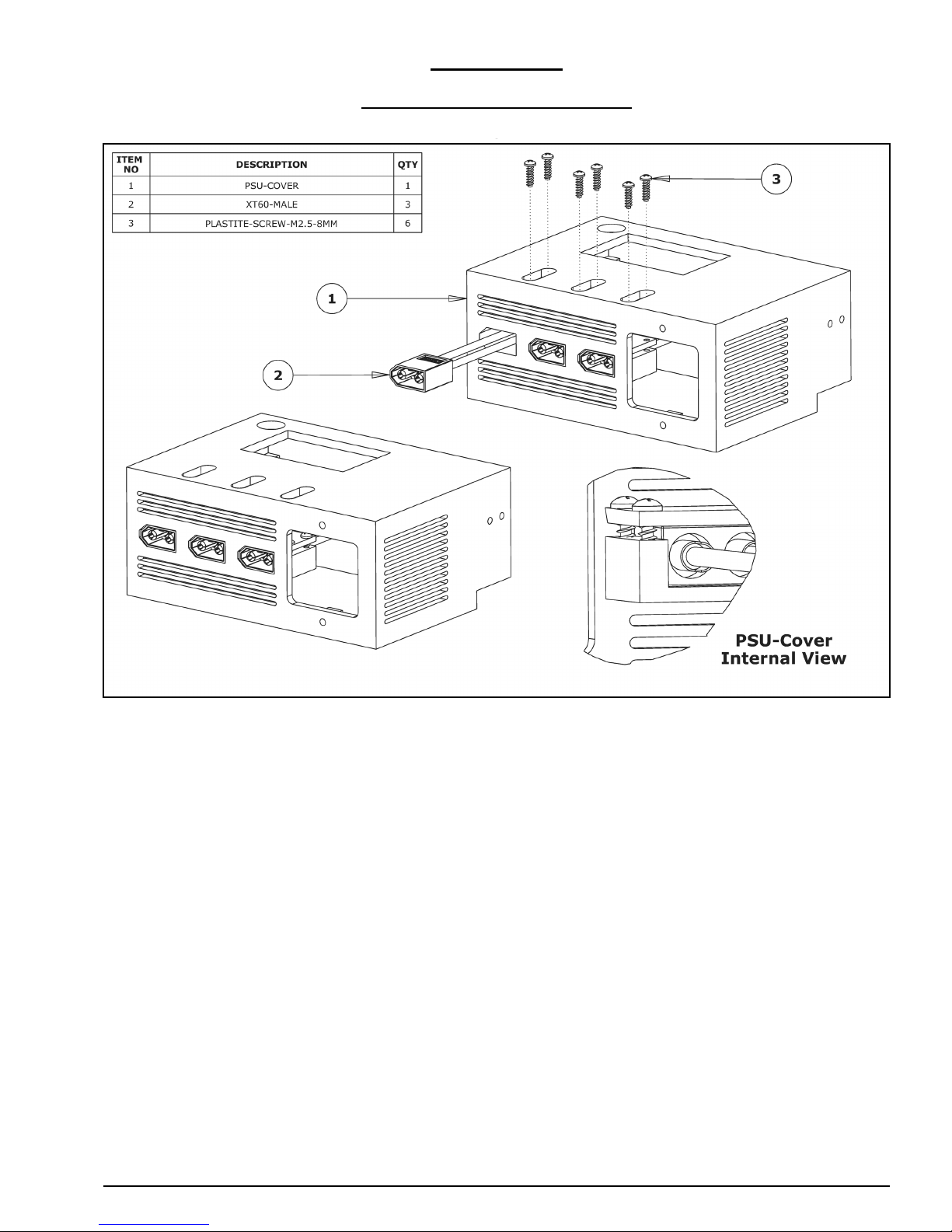
3.1.1 Securing XT60-Male Outputs
A. Insert the XT60-Male connectors into the provided insets on the PSU-Cover. They
should sit flush with the front of the PSU-Cover. Completion of this kit only requires 2
x XT60-Male connectors. The left-most XT60-Male connector is not needed for the
operation of this machine, but is included so you have the option to add additional
accessories. For safety reasons, if you do not intend to use it, do not attach it to the
PSU-Cover, and leave that inset empty.
B. Secure each XT-Male connector using 2 x Plastite-Screw-M2.5-8mm through the holes
provided on the securing tab as seen on the internal view. When initially placing the
screw, it is helpful to hold each screw in place using tweezers or long nose pliers.
Page 20
WorkBee CNC Power Supply Assembly 18
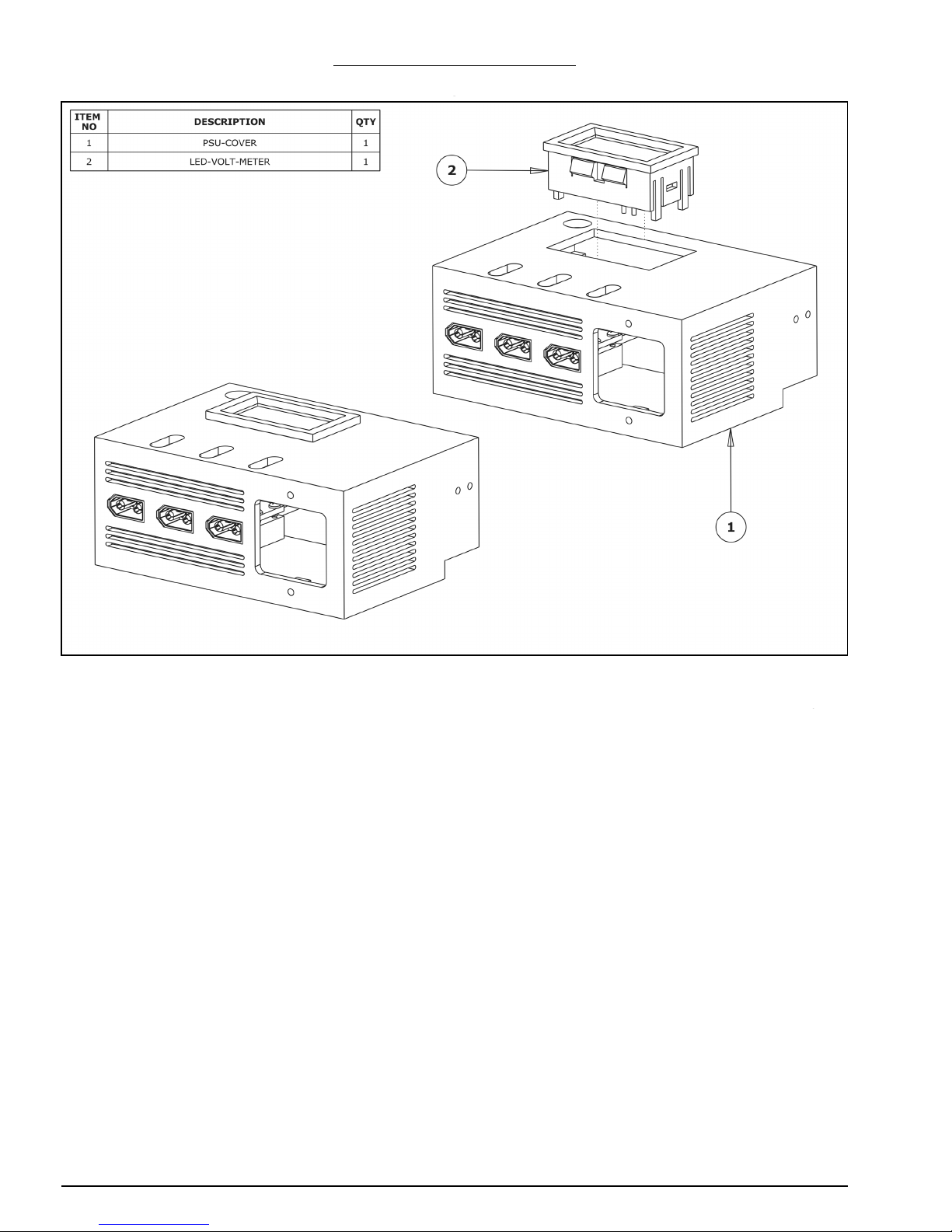
3.1.2 Inserting LED-Volt-Meter
A. Gently push the LED-Volt-Meter into the provided gap on the top of the PSU Cover.
The wires on the LED-Volt-Meter should be oriented to the front of the PSU-Cover.
Page 21
WorkBee CNC Power Supply Assembly 19
3.2 Input
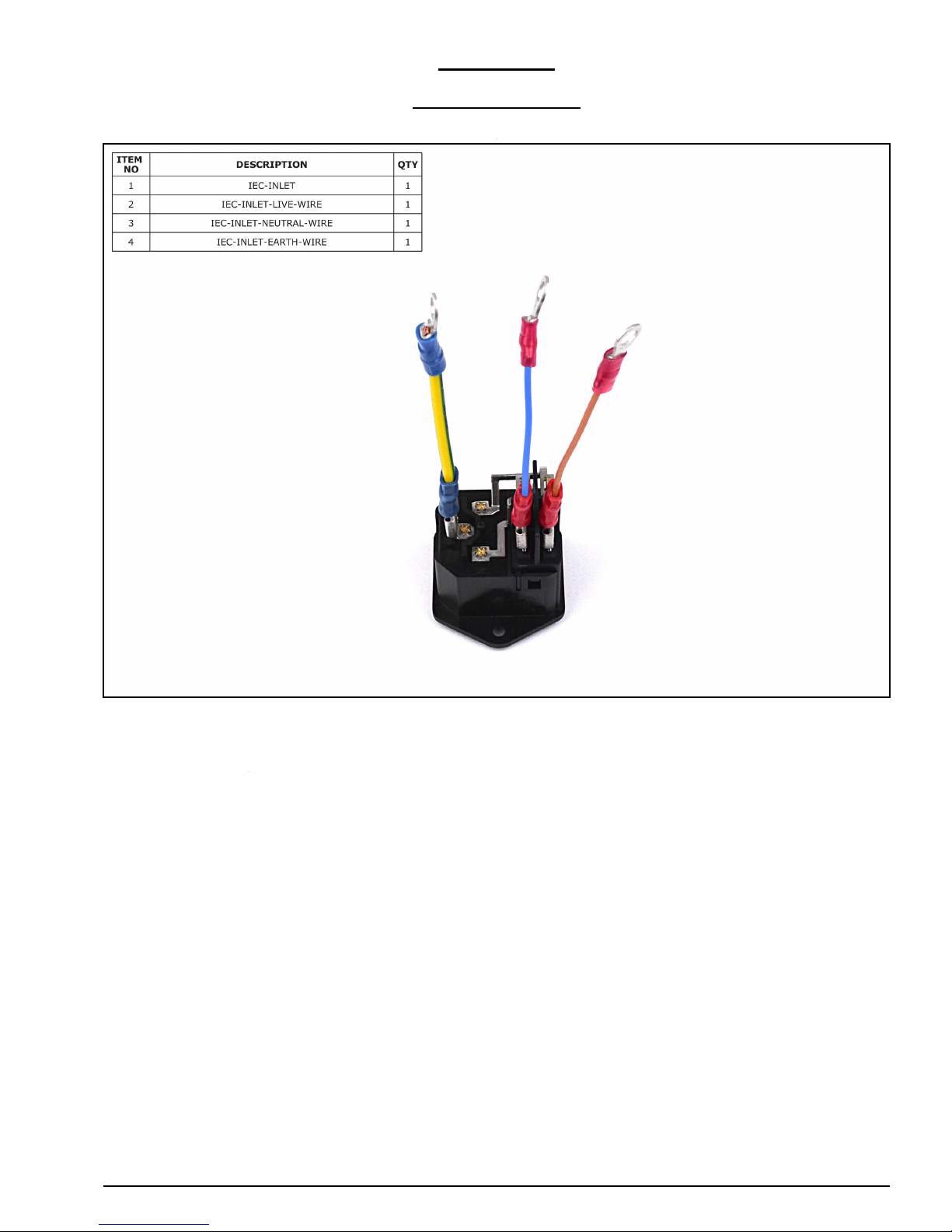
3.2.1 IEC-Inlet Wires
A. Attach the receptacle end of the IEC-Inlet-Live-Wire, IEC-Inlet-Neutral-Wire & IEC-
Inlet-Earth-Wire to their respective terminal tabs on the IEC-Inlet, as seen in the
above image.
Page 22
WorkBee CNC Power Supply Assembly 20
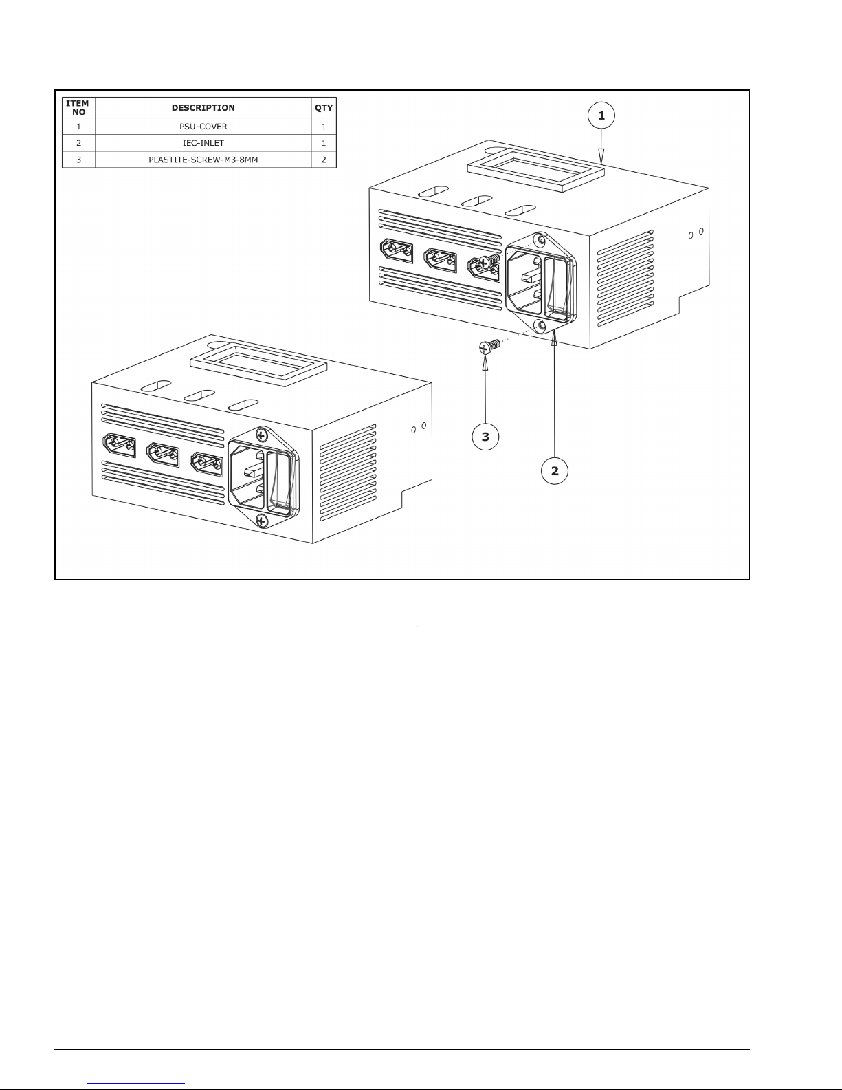
3.2.2 Attaching IEC-Inlet
A. Secure the assembled IEC-Inlet to the PSU-Cover using 2 x Plastite-Screw-M3-8mm.
Ensure the switch is on the right hand side.
Page 23
WorkBee CNC Power Supply Assembly 21
3.3 Connecting PSU-Cover
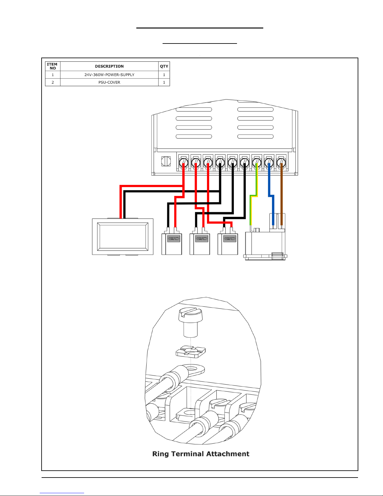
3.3.1 Connecting Wires
Page 24

WorkBee CNC Power Supply Assembly 22
A. Bring the front of the 24V-360W-Power-Supply and PSU Cover close together.
B. Following the wiring diagram, first connect both wires of the right and center XT60-
Male connectors to the 24V-360W-Power-Supply. As seen on the ring terminal attachment view, the terminal screws on the 24V-360W-Power-Supply should first go
through the terminal plate, then through the ring terminal on the wires, and then into
the threaded hole on the 24V-360W-Power-Supply.
C. If you did not attach the left-most XT60-Male connector to the PSU-Cover, then only
connect the LED-Volt-Meter to the last empty output terminals. If you intend to use a
third XT60-Male connector, then it must also be connected with the LED-Volt-Meter to
the same terminal points on the 24V-360W-Power-Supply. This simply involves screwing through two ring terminals (instead of one) and ensuring they are of the same
polarity. The top ring terminal will have to be folded up in order to clear the plastic
sleeve on the lower one.
D. Finally, connect the three IEC-Inlet wires to the 24V-360W-Power-Supply. The IEC-
Inlet-Earth-Wire is very inflexible compared to the previous ones, so this wire may
take some force to get into position.
Page 25
WorkBee CNC Power Supply Assembly 23
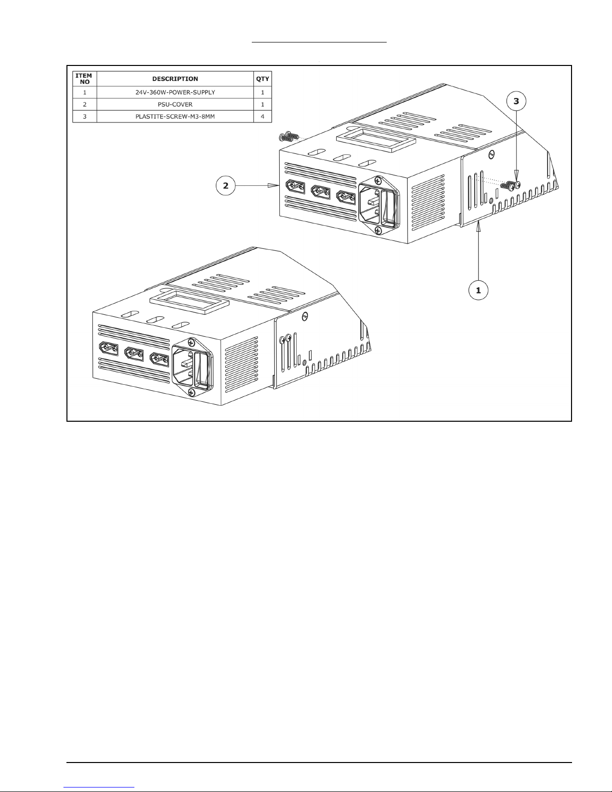
3.3.2 Attaching PSU-Cover
A. Mate the PSU-Cover to the 24V-360W-Power-Supply. This may be very fiddly to ini-
tially get into position, so do take an extra bit of time to do so.
B. On each side, secure the PSU-Cover using two Plastite-Screw-M3-8mms. Go through
the slots on the metal casing of the 24V-360W-Power-Supply, and then into the holes
on the PSU-Cover.
Page 26
WorkBee CNC Power Supply Assembly 24
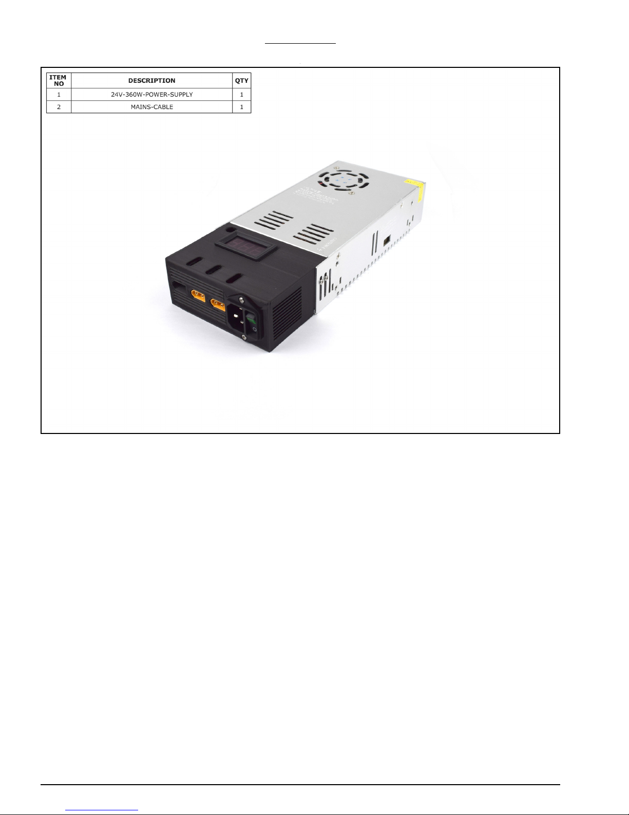
3.3.3 Testing
A. Insert the end of the Mains-Cable into the IEC-Inlet on the 24V-360W-Power-Supply.
B. Plug the Mains-Cable into a wall socket and switch it on. If the LED-Volt-Meter comes
on, this indicates the 24V-360W-Power-Supply has power. If it doesn’t come on, this is
most likely because the switch on the IEC-Inlet is turned off; turn this on.
C. Once switched on, the LED-Volt-Meter should read 24.0. If it does not read 24.0, the
screw through the hole towards the top left of the LCD can be used to adjust the voltage. Use a screwdriver to adjust the voltage to 24.0, and take caution to not touch
any metal parts with the screwdriver.
D. The Power Supply assembly is now complete and can be turned off and placed
towards the back left of the machine near, the Y-Axis-Fixed-End-Assembly.
Page 27

WorkBee CNC Limit Switches & Wire Routing 25
4.0 Limit
Switches &
Wire Routing
Page 28
WorkBee CNC Limit Switches & Wire Routing 26
4.1 Limit Switches
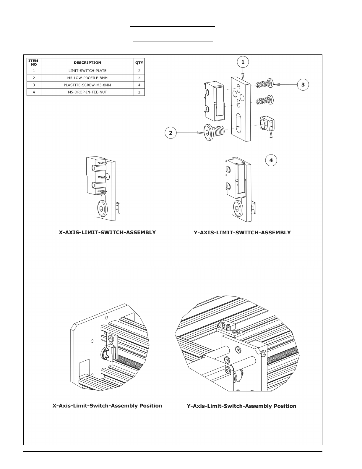
4.1.1 X & Y Limit Switches
Page 29

WorkBee CNC Limit Switches & Wire Routing 27
A. Attach the Limit-Switch that was inserted in Section 2.1.5 to a Limit-Switch-Plate
using 2 x Plastite-Screw-M3-8mms, the Plastite-Screw-M3-8mms will self thread into
the Limit-Switch. Make sure the Limit-Switch is orientated as the Y-Axis-Limit-SwitchAssembly above. Finally attach a M5-Low-Profile-8mm bolt, and on the end slightly
thread a M5-Drop-In-Tee-Nut.
B. Repeat Step A for the last Limit-Switch, this one has not been inserted anywhere yet.
Note the different orientation as seen in the X-Axis-Limit-Switch-Assembly above.
C. Attach the Y-Axis-Limit-Switch-Assembly to the left hand Y-Axis C-Beam extrusion (if
looking from the front). It should be attached to the inner slot on the far end of the CBeam extrusion. The distance between the Limit-Switch-Plate and the end of the
extrusion should be 13mm.
D. Attach the X-Axis-Limit-Switch-Assembly to the back side of the X-Axis C-Beam extru-
sion. It should be attached to the top slot on the far left side (if looking from the
back). The distance between the Limit-Switch-Plate and the end of the extrusion
should be 10mm.
Page 30
WorkBee CNC Limit Switches & Wire Routing 28
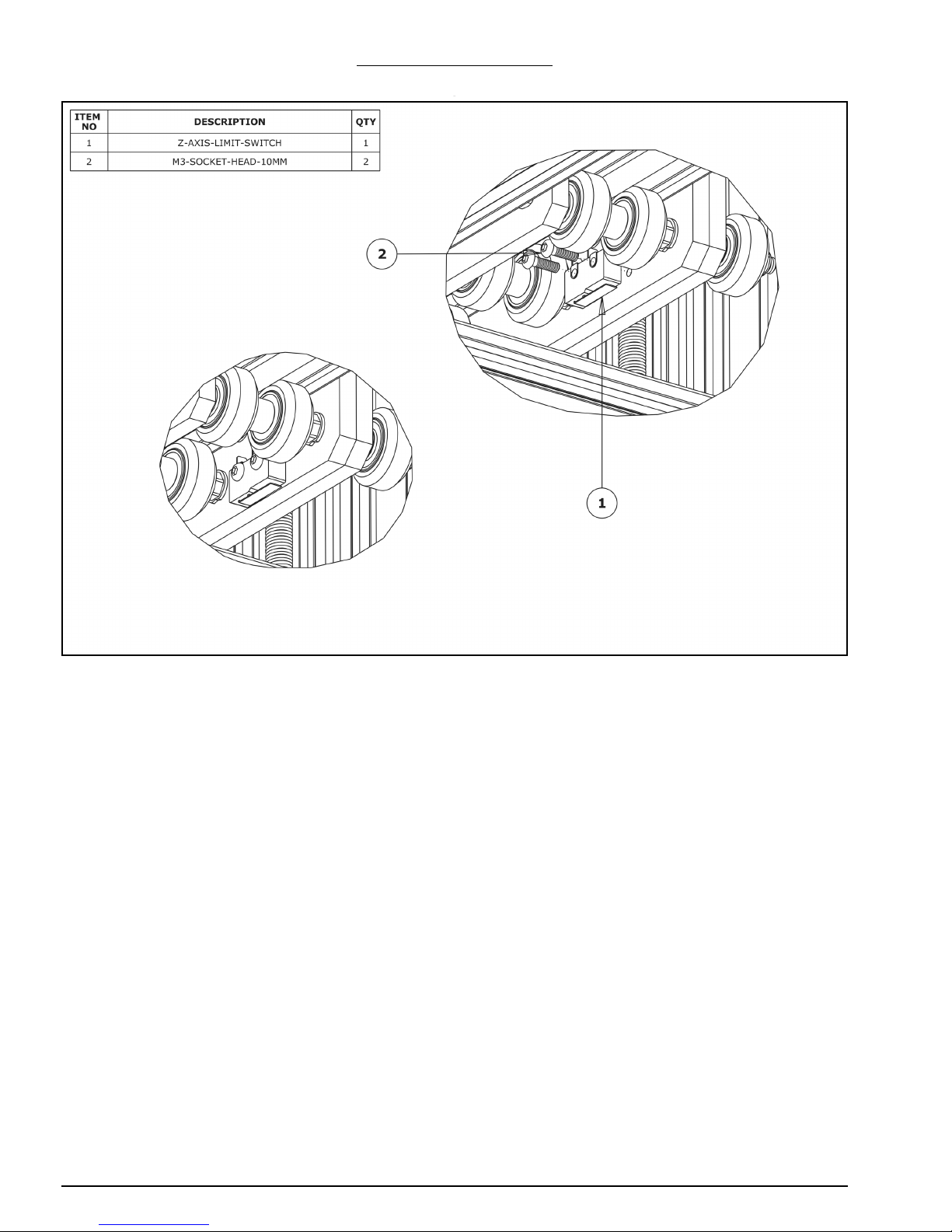
4.1.2 Z-Axis Limit Switch
A. Attach the Z-Axis limit switch to the threaded holes on the X-Plate-Front using 2 x M3-
Socket-Head-10mm bolts, in the orientation above.
Page 31
WorkBee CNC Limit Switches & Wire Routing 29
4.2 Wire Routing
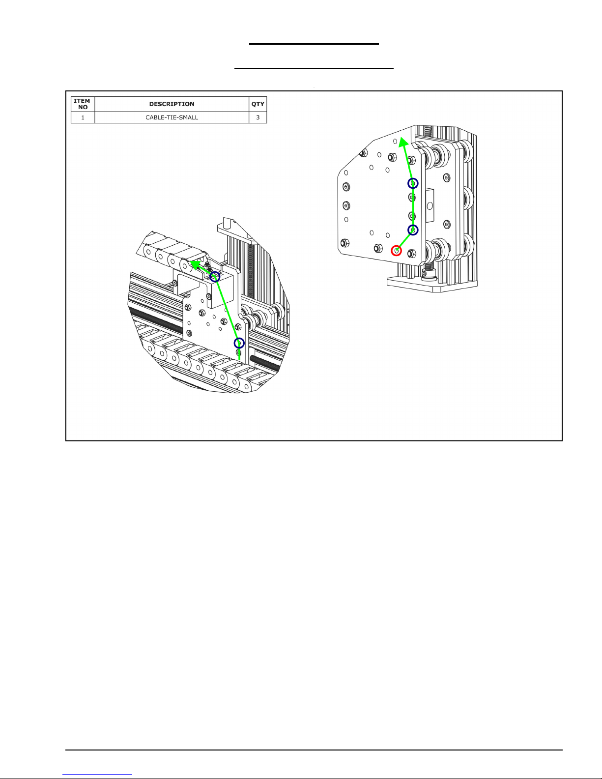
4.2.1 Z-Axis Limit Switch Wiring
A. As shown by the green line above, bring the Z-Limit-Switch wires through the hole
outlined with a red circle, up the X-Plate-Back, and feed it through the X-Drag-Chain.
Secure the wires using Cable-Tie-Smalls to the points marked with blue circles above.
To stop it snagging on anything the wire should be pulled taught.
Page 32
WorkBee CNC Limit Switches & Wire Routing 30
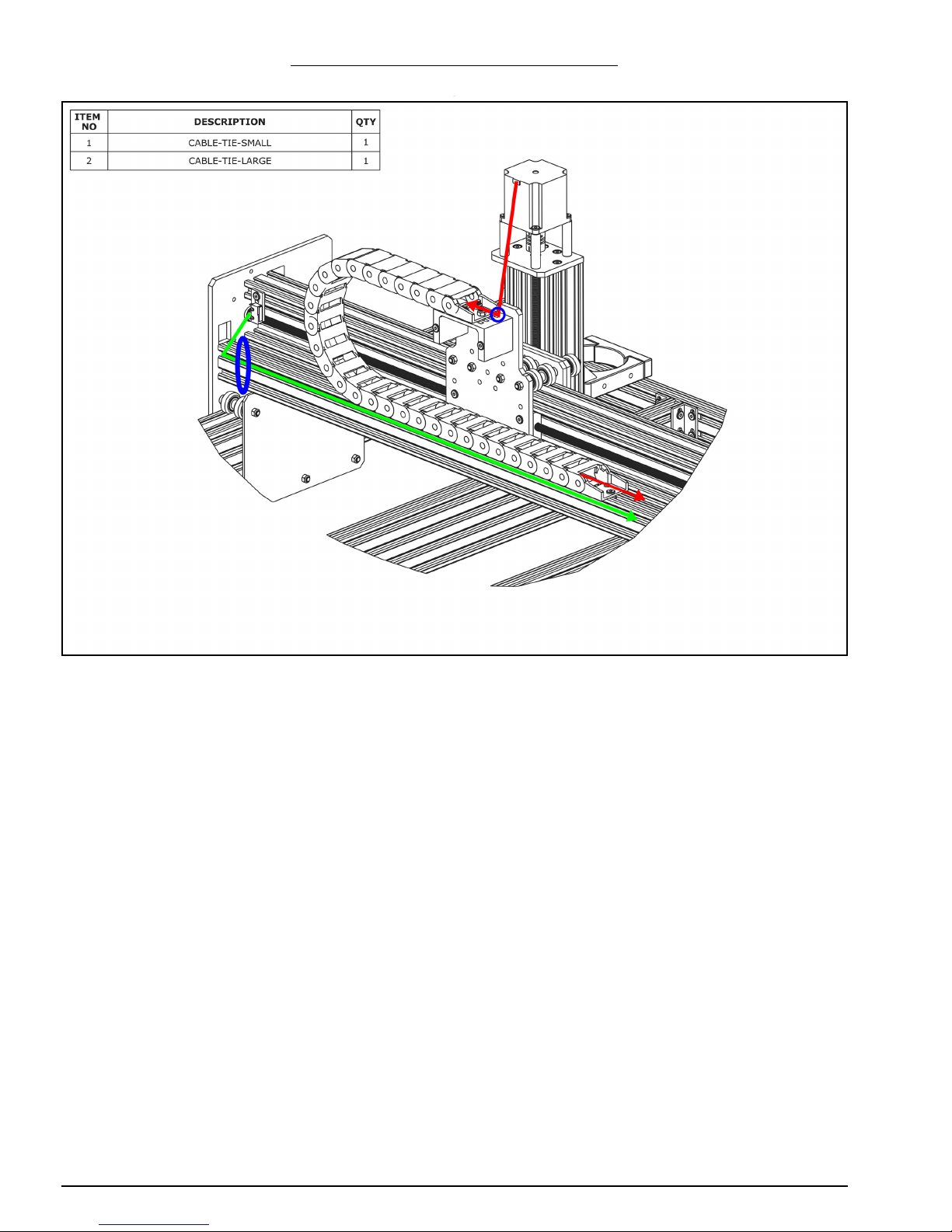
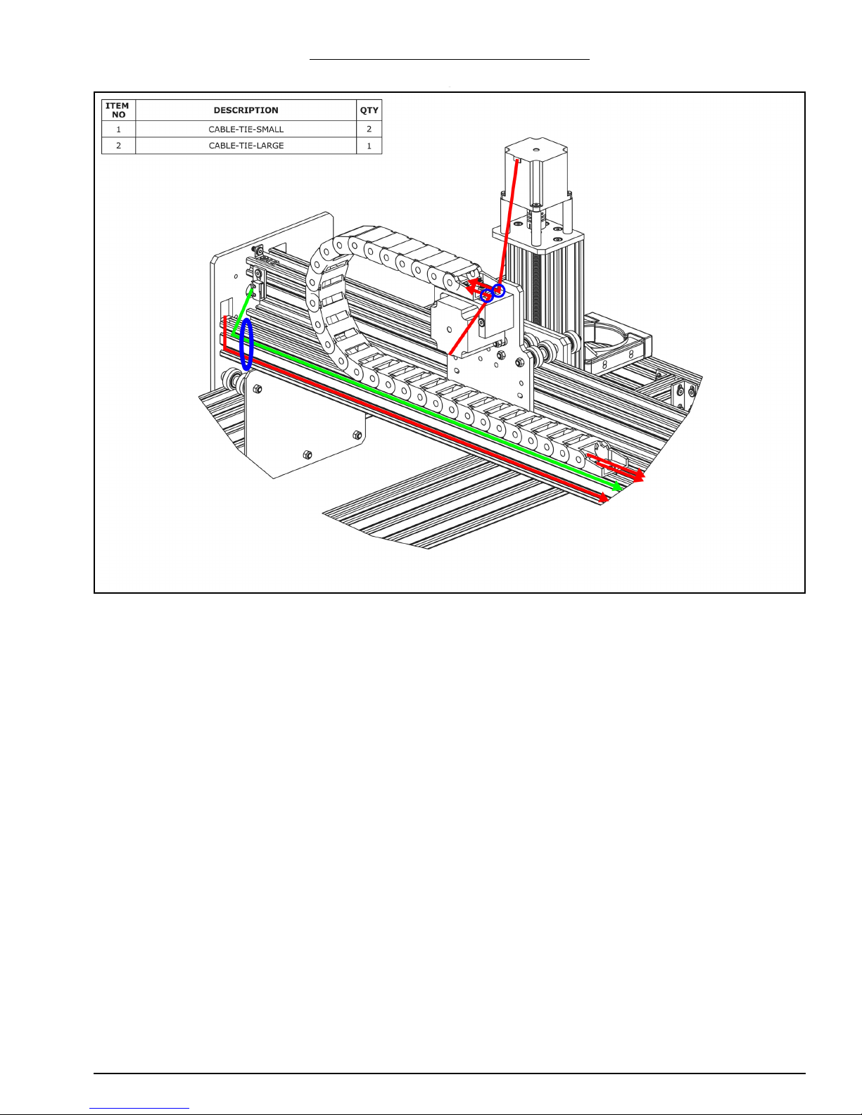
4.2.2 Screw Driven - Gantry Wire Routing
A. For the stepper motor wire that is inside the X-Drag-Chain, connect it to the pigtail on
Z-Axis stepper motor. Making sure there is enough slack for the full travel of the ZAxis, secure the wire to the X-Drag-Moving-End-Mount using a Cable-Tie-Small,
shown by the small blue circle above.
B. The lead on the X-Axis limit switch should be secured to the V-Slot-2040-750mm
using a Cable-Tie-Large at the position shown by the blue oval above. Then run the
lead along to the other end of V-Slot-2040-750mm - it can be tucked into one of the
slots.
Page 33
WorkBee CNC Limit Switches & Wire Routing 31
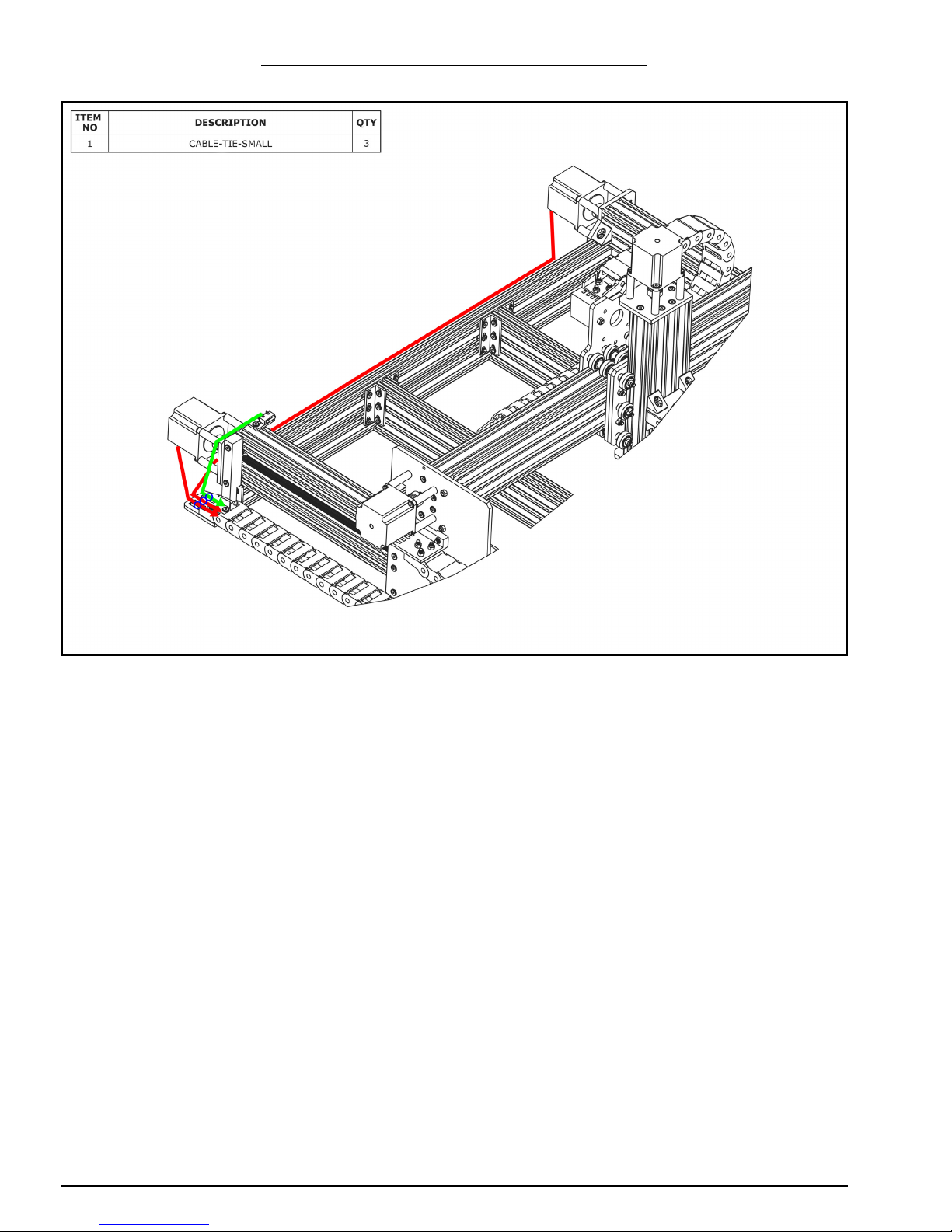
4.2.3 Belt Driven - Gantry Wire Routing
A. For one of the stepper motor wires that is inside the X-Drag-Chain, connect it to the
pigtail on Z-Axis stepper motor. Making sure there is enough slack for the full travel of
the Z-Axis, secure the wire to the X-Drag-Moving-End-Mount using a Cable-Tie-Small,
shown by the small blue circle above.
B. For the second stepper motor wire connect it to the pigtail on the X-Axis stepper
motor wire. Secure it to the X-Drag-Moving-End-Mount in a similar fashion as in Step
A
C. Connect a stepper motor wire to the pigtail on the right hand Y-Axis stepper motor (as
if looking from the front). Feed it through the square hole on the Y-Plate. The lead on
the X-Axis limit switch and stepper motor wire should be secured to the V-Slot-2040750mm using a Cable-Tie-Large at the position shown by the blue oval above. Then
run the wires along to the other end of V-Slot-2040-750mm - they can be tucked into
the slots.
Page 34
WorkBee CNC Limit Switches & Wire Routing 32
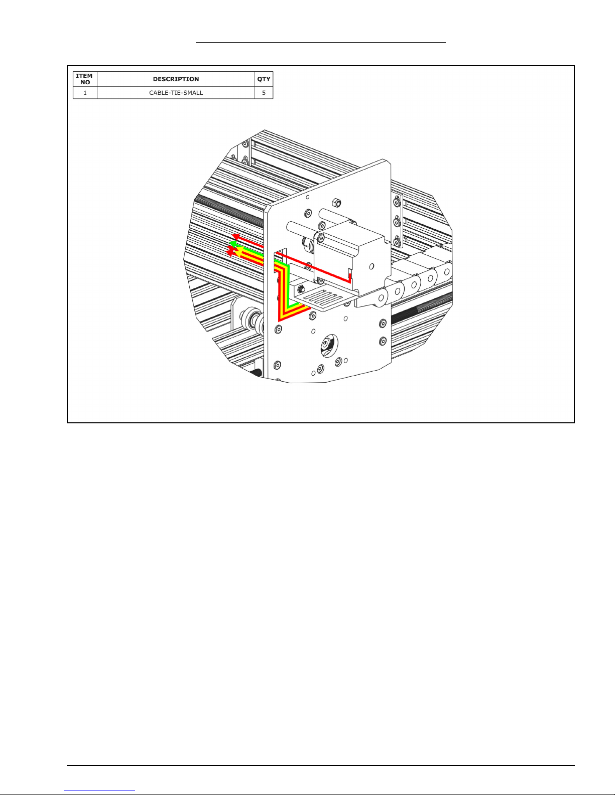
4.2.4 Screw Driven - Y-Axis Wire Routing - Part 1
A. Connect the two stepper motor wires in the Y-Drag-Chain to the pigtails on the Y-Axis
stepper motors. In Section 2.1.5 Step B, one of the stepper motor wires will be longer
than the other, the longer wire should connect to the right hand stepper motor.
B. Secure the stepper motor wires to the Y-Axis-Fixed-End-Mount using Cable-Tie-
Smalls. The wire for the right hand stepper motor can be tucked into a slot on one of
the extrusions along the back.
C. Secure the lead on the Y-Axis limit switch to the Y-Axis-Fixed-End-Mount using a
Cable-Tie-Small.
Page 35
WorkBee CNC Limit Switches & Wire Routing 33
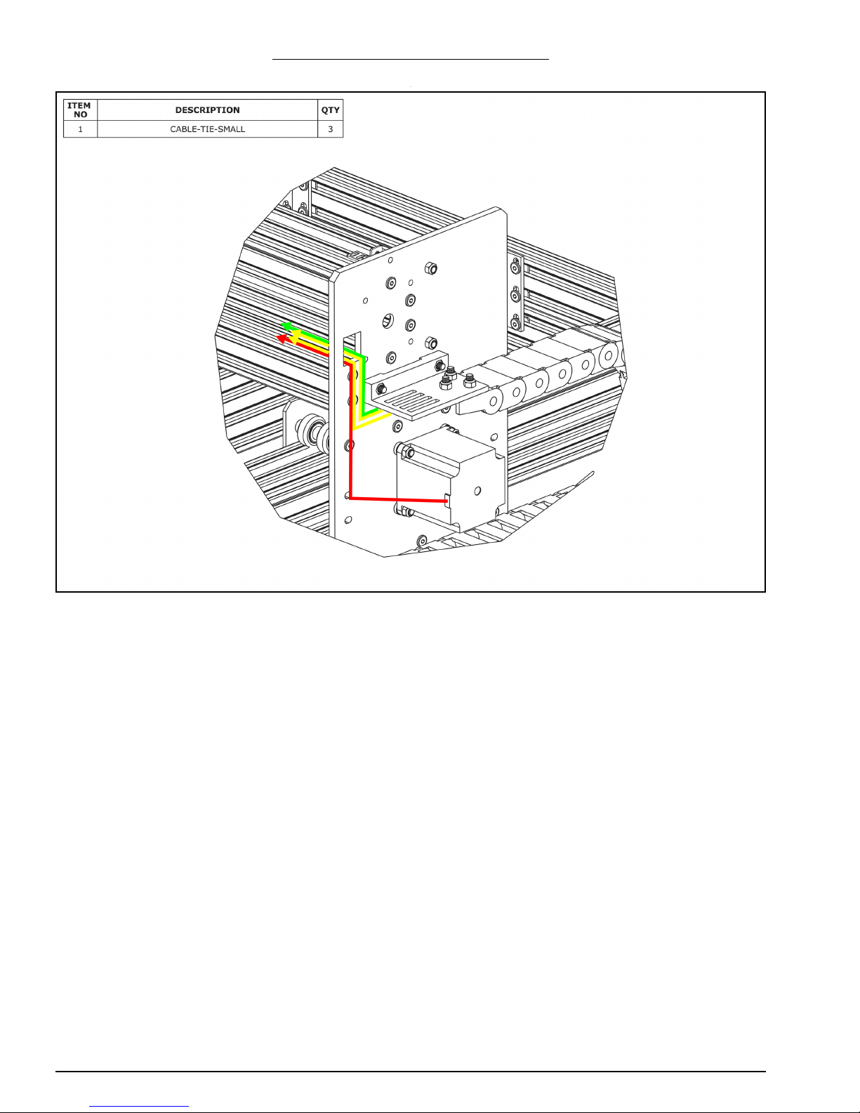
4.2.5 Screw Driven - Y-Axis Wire Routing - Part 2
A. Connect a stepper motor wire to the pigtail on the X-Axis stepper motor and feed it
through the square hole on the Y-Plate
B. Inside the Y-Drag-Chain there should be two stepper motor wires (red above), two
power supply wires (yellow above), and a limit switch wire (green above). Feed all of
these through the square hole on the Y-Plate. Remove any slack inside the Y-DragChain, and then secure these 5 wires to the Y-Drag-Chain-Moving-End-Mount using
Cable-Tie-Smalls.
Page 36
WorkBee CNC Limit Switches & Wire Routing 34
4.2.6 Belt Driven - Y-Axis Wire Routing
A. Connect a stepper motor wire to the pigtail on the left hand Y-Axis stepper motor (if
looking from the front) and feed it through the square hole on the Y-Plate
B. Inside the Y-Drag-Chain there should be two power supply wires (yellow above), and
a limit switch wire (green above). Feed all of these through the square hole on the YPlate. Remove any slack inside the Y-Drag-Chain, and then secure these 3 wires to the
Y-Drag-Chain-Moving-End-Mount using Cable-Tie-Smalls.
Page 37

WorkBee CNC CNC xPro Assembly 35
5.0 CNC xPro
Assembly
Page 38
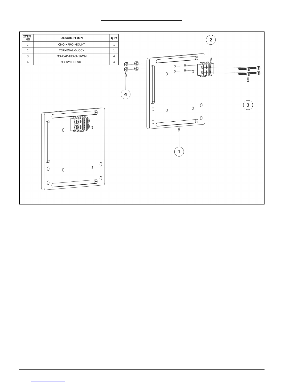
WorkBee CNC CNC xPro Assembly 36
5.0.1 Terminal-Block Attachment
A. Attach the Terminal-Block to the CNC-xPro-Mount using 4 x M3-Cap-Head-16mm
Bolts. Tighten the M3-Cap-Head-16mm Bolts to M3-Nyloc-Nuts on the other side of
the CNC-xPro-Mount. Double check that the Terminal-Block is mounted to the correct
side of the CNC-xPro-Mount.
Page 39
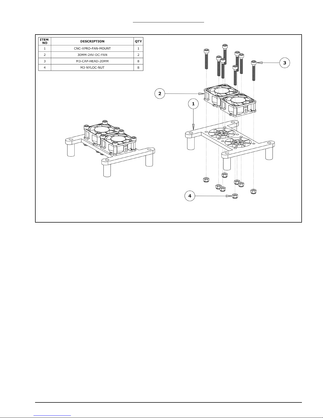
WorkBee CNC CNC xPro Assembly 37
5.0.2 Fan Mount Assembly
A. Attach 2 x 30mm-24V-DC-Fans to the CNC-xPro-Fan-Mount using 8 x M3-Cap-Head-
20mm bolts and 8 x M3-Nyloc-Nuts. Ensure that the 30mm-24V-DC-Fans are blowing
downward by ensuring that the side of the fan which the wires sit on is against the
CNC-xPro-Fan-Mount. Make sure that the power wires on the 30mm-24V-DC-Fans are
both on the same side of the CNC-xPro-Fan-Mount.
Page 40
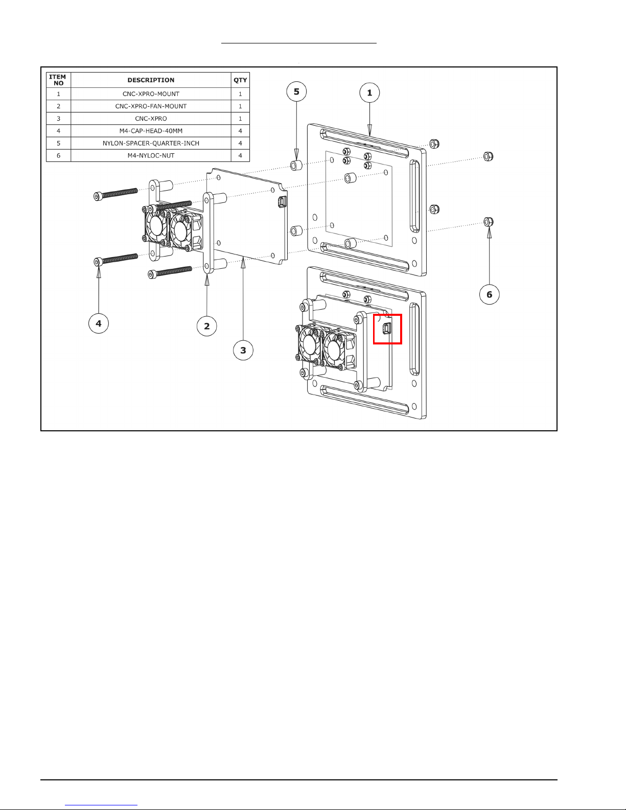
WorkBee CNC CNC xPro Assembly 38
5.0.3 Attaching The CNC-xPro
A. Insert 4 x M4-Cap-Head-40mm bolts through the previously assembled CNC-xPro-
Fan-Mount, and then through the CNC-xPro and each through a Nylon-Spacer-Quarter-Inch. Finally, go through the CNC-xPro-Mount and tighten each bolt into a M4Nyloc-Nut. The CNC-xPro-Fan-Mount should be orientated so the power wires are on
the same side as the Terminal-Block. The CNC-xPro should be orientated so the USB
terminal is in the same position as shown by the red square above.
Page 41
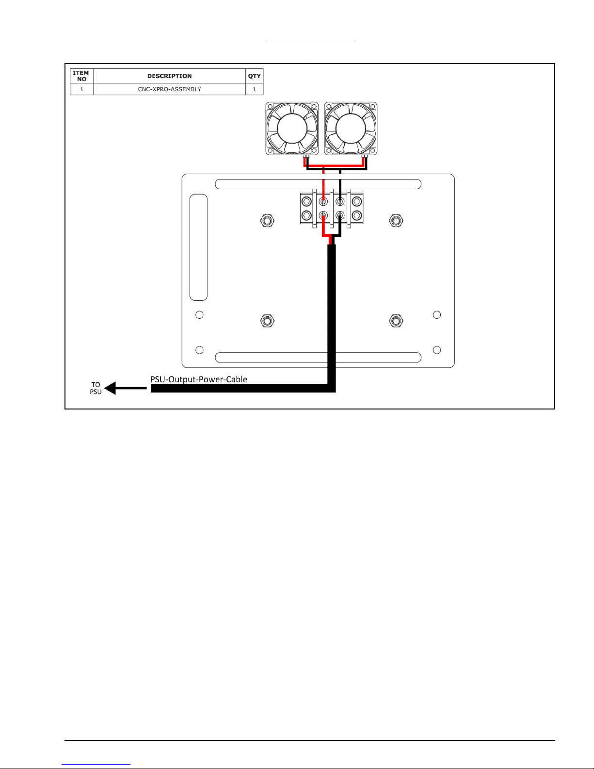
WorkBee CNC CNC xPro Assembly 39
5.0.4 Fans Wiring
A. Locate both red wires coming from the two 30mm-24V-DC-30mm-Fans, and strip
approximately 20mm of sheaving. Twist the two exposed copper cores together to
form one.
B. Connect the red wires from the 30mm-24V-DC-30mm-Fans to the Terminal-Block, as
shown above. To connect a wire, unscrew the respective screw from the TerminalBlock. Bend the exposed copper core of the wire around the screw. Screw the screw
back into the Terminal-Block.
C. Repeat Step A & B for the two black wires of the 30mm-24V-DC-30mm-Fans.
D. With one of the PSU-Output-Power-Cables already positioned on the machine, strip
back approximately 50mm of the black sheaving from the bare end to expose the red
and black wires underneath. Strip back approximately 20mm of the sheaving from the
red and black wires to expose the conductive core underneath. Connect these wires to
the Terminal-Block as in Step B.
Page 42
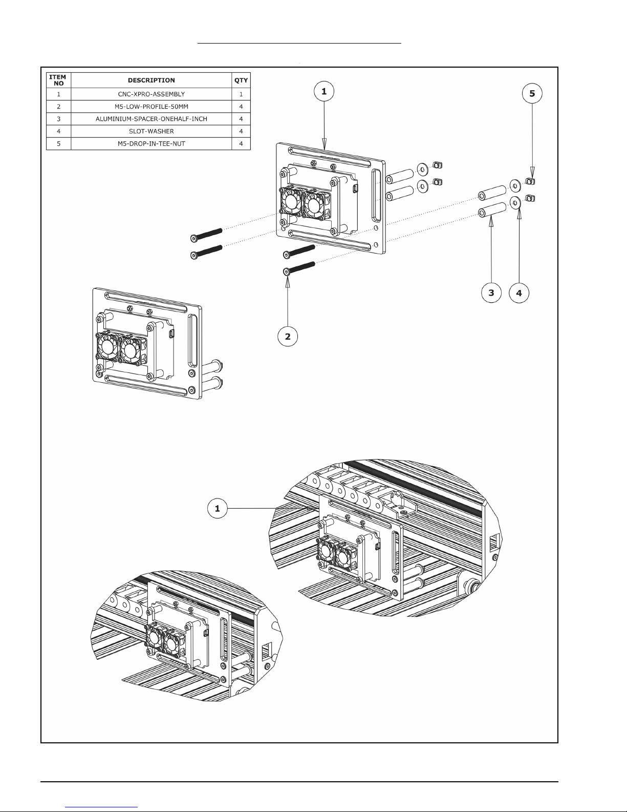
WorkBee CNC CNC xPro Assembly 40
5.0.5 Mounting the CNC-xPro Assembly
Page 43

WorkBee CNC CNC xPro Assembly 41
A. Insert 4 x M5-Low-Profile-50mm bolts through each mounting hole on the CNC-xPro-
Mount.
B. On to each M5-Low-Profile-50mm bolt slide an Aluminium-Onehalf-Inch and a Slot-
Washer. The rounded face of the Slot-Washer should be flush against the AluminiumOnehalf-Inch.
C. On to the end of each M5-Low-Profile-50mm bolt, slightly thread a M5-Drop-In-Tee-
Nut.
D. Bring the CNC-xPro-Assembly to the back of the WorkBee X-Gantry, and align the M5-
Low-Profile-50mm bolt assemblies from Step A/B/C with the backward facing top and
bottom slots on the V-Slot-2040-750mm.
E. With the M5-Low-Profile-50mm bolt assemblies aligned, mate the CNC-xPro-Assembly
with the V-Slot-2040-750mm slots. It should be roughly 10mm from the end of VSlot-2040-750mm.
F. Screw each M5-Low-Profile-50mm bolt to engage the M5-Drop-In-Tee-Nut with the
slot. Fully tighten each M5-Low-Profile-50mm bolt.
Page 44

WorkBee CNC Wiring & Commissioning 42
6.0 Wiring &
Commissioning
Page 45
WorkBee CNC Wiring & Commissioning 43
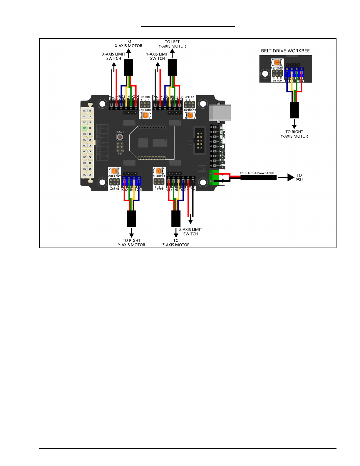
6.1 CNC-xPro Wiring
A. Following the wiring diagram above, strip and connect the second PSU-Output-Power-
Cable to the power input terminal on the CNC-xPro.
B. Connect the 4 x NEMA23-Stepper-Motors to the CNC-xPro as shown above. Take note
of the order of the wire colours. For the belt drive version of the WorkBee notice that
the colour order is reversed on the A driver (this is also true for a 1000x1500mm Belt
& Screw drive WorkBee).
C. Wire in the 3 Limit-Switches, note the polarity of the wires in the image above.
D. Plug both PSU-Output-Power-Cables into the XT60-Male Outputs on the assembled
24V-360W-Power-Supply. Do not tidy up the wiring just yet, as this is best left until
the machine has been fully checked to ensure that it is operating correctly.
E. If interested, it is a good idea to read the CNC-xPro Wiki for more in-depth informa-
tion: https://github.com/Spark-Concepts/xPRO/wiki
Page 46
WorkBee CNC Wiring & Commissioning 44
6.2 Software & Machine Settings
6.2.1 Installing Universal G-Code Sender (UGS)
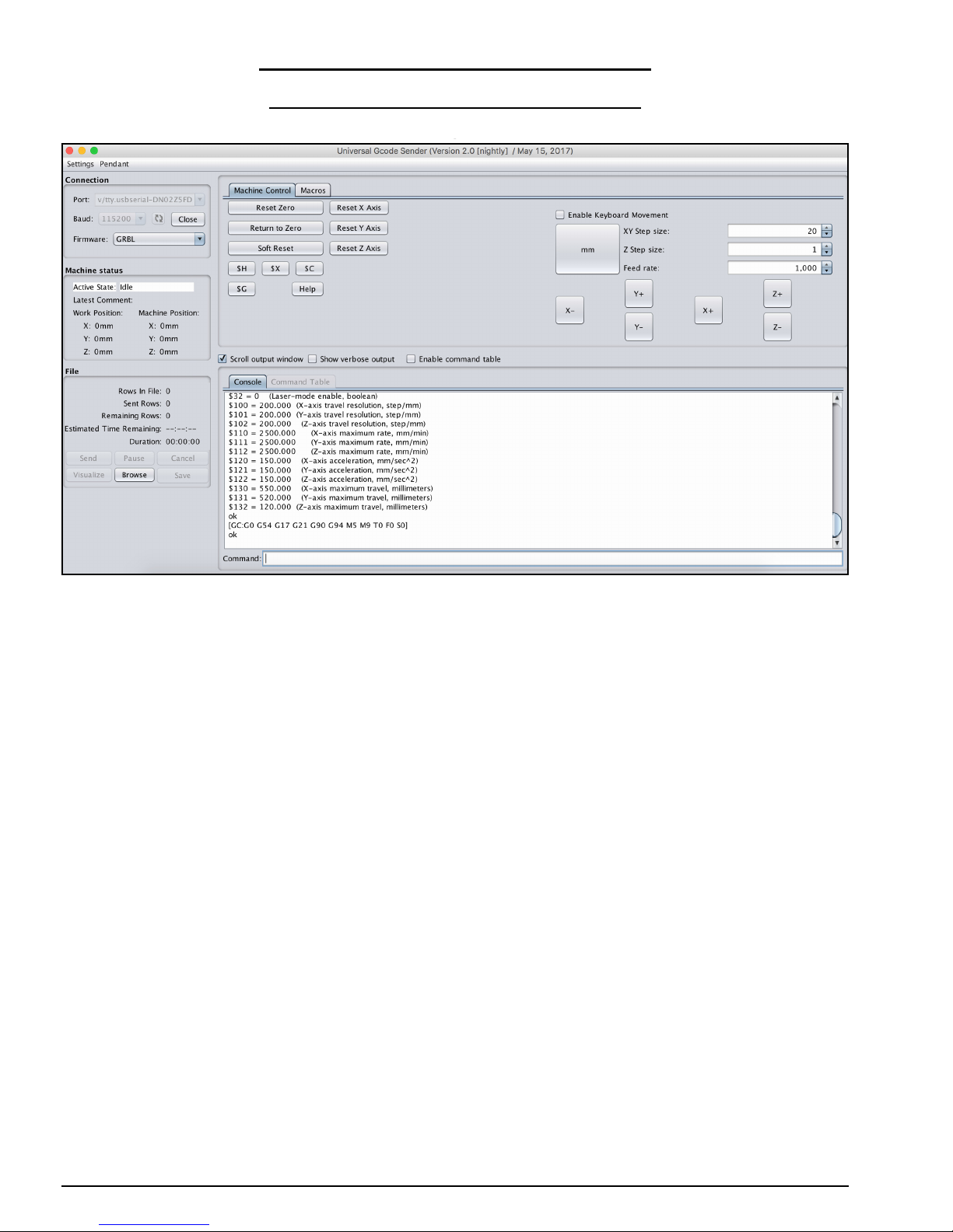
A. Universal G-Code Sender (UGS) is a simple Java-based cross platform G-Code sender.
Download the latest version from: http://ooznest.co.uk/UniversalGcodeSenderv2.0.0-stable.zip
B. Unzip the folder to a location of your choosing.
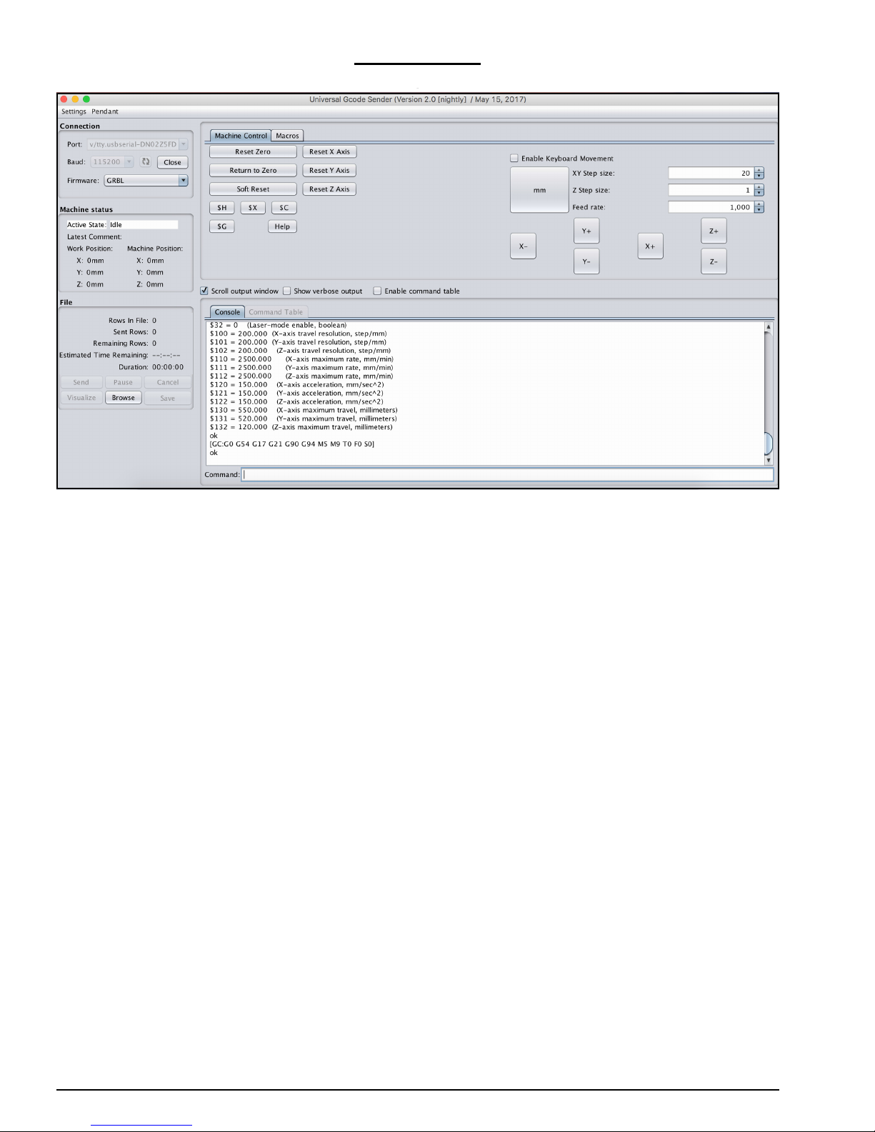
C. Run the file named ‘UniversalGcodeSender.jar’ and UGS should open and look similar
to the above image.
D. Download and install the appropriate drivers for the chip used on the CNC-xPro from:
http://www.ftdichip.com/Drivers/VCP.htm. For Windows, under the comments section
there is a link to an executable setup file.
E. Using the supplied USB-Cable, connect the CNC-xPro to your computer.
F. In UGS set the ‘Baud’ to ‘115200’ and ‘Firmware’ to ‘GRBL’. Press the refresh symbol.
G. On the ‘Port’ drop down list find the CNC-xPro, if on a Mac it should look similar to
what is selected in the image above. If on a windows computer, it will show up as a
COM port. Once found click ‘Open’ and UGS should successfully connect to the CNCxPro. The Console output will show information similar to the above.
Page 47
WorkBee CNC Wiring & Commissioning 45
6.2.2 Configuring The Firmware
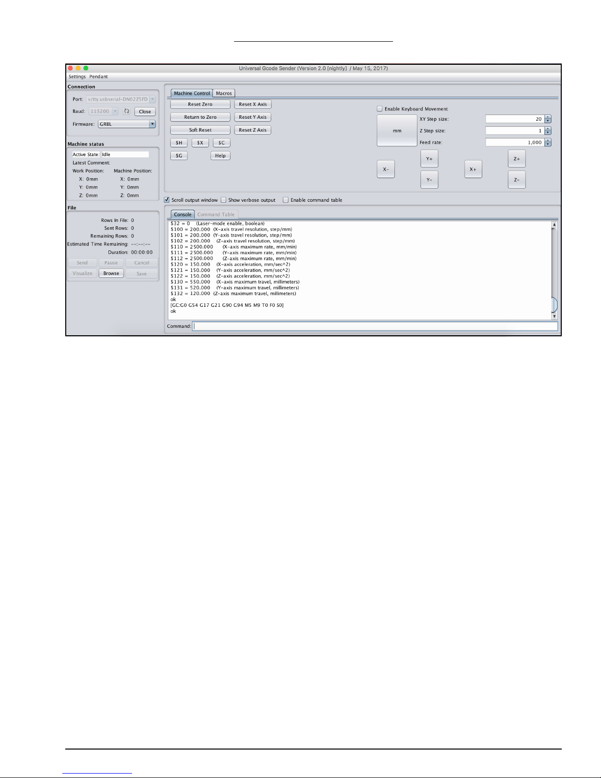
A. Under the large white console output, there is a text input area labeled ‘Command:’
where G-Code commands can be sent to the CNC-xPro. To bring up the current firmware settings type ‘$$’ and press enter.
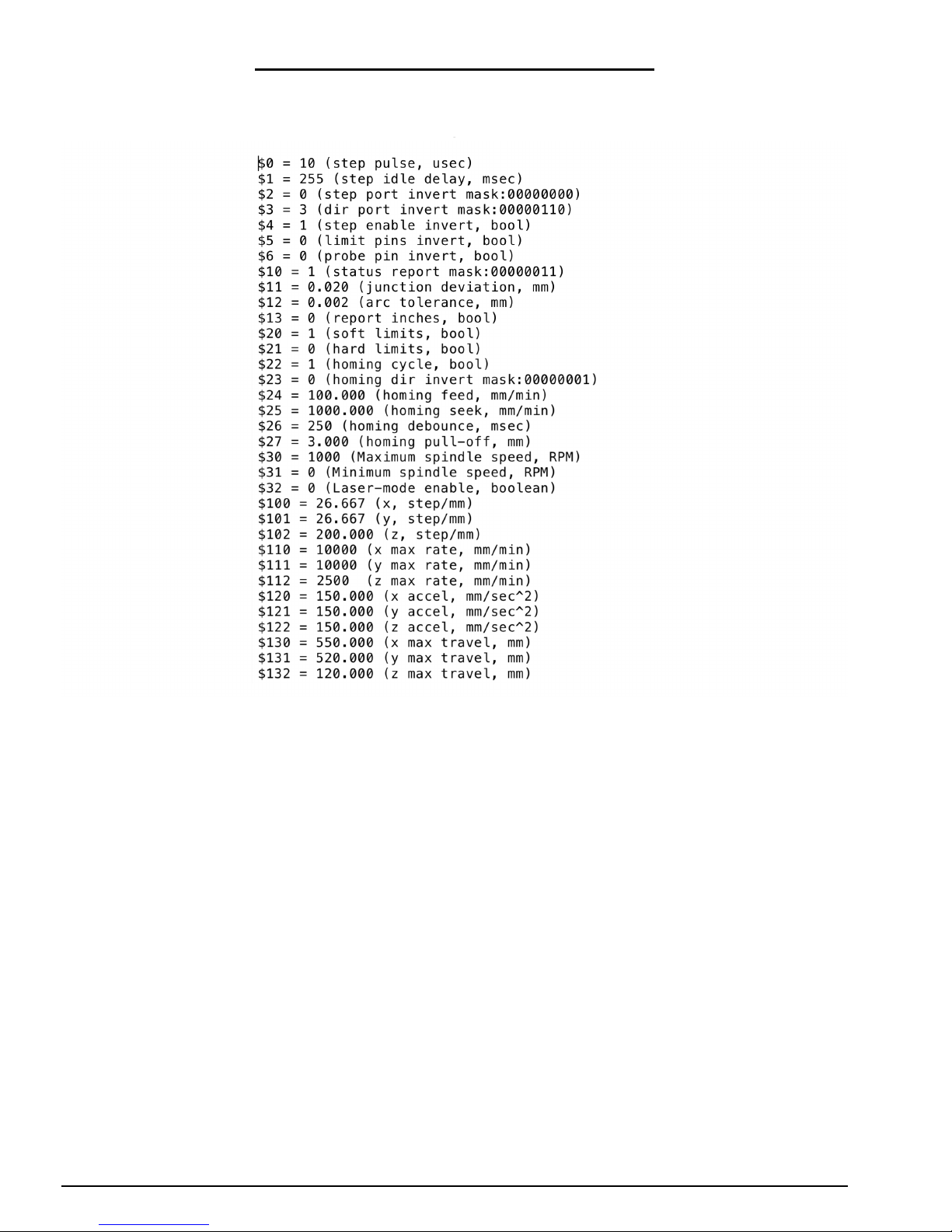
B. In Appendix B we have provided a set of recommended settings for each drive version
of the WorkBee. Each setting has an id number and a value, and in order to change a
setting to a new value, enter $id = new value. For instance, if setting number 100 is
incorrect when compared to Appendix B, correct it by entering $100 = 200. Do this for
all the settings in Appendix B, choosing the list that is appropriate for the drive of
machine you have.
C. Setting number 130 and 131 will depend on the size of the machine you have. The
values to enter here should be 200mm less than your X-Axis size and 230mm less
than your Y-Axis size. For instance, on a 750x750mm machine the values for 130 and
131 should be 550 and 520 respectively.
D. If interested, it is a good idea to read the GRBL Firmware Wiki for more in-depth
information: https://github.com/grbl/grbl/wiki
Page 48
WorkBee CNC Wiring & Commissioning 46
6.3 Testing
A. Next to each driver on the CNC-xPro, there is a current control pot, and these can be
adjusted using the Ceramic-Screwdriver. Rotate clockwise to increase the current, and
anti-clockwise to decrease. Turn each one clockwise until it stops, and then back 1/8th
of a full turn. This is the ideal setting for the drivers.
B. Switch on the 24V-360W-Power-Supply, and the 2 x 30mm-24V-DC-Fan’s should acti-
vate. If they do not activate, check the wiring in Step 5.0.4. If the machine is in an
alarm state press the $X button.
C. Looking from the front of the machine, the correct axes machine motion is: X-Axis
positive to the right, Y-Axis positive going away, Z-Axis positive going up. To test this
in UGS, click on the ‘Machine Control’ tab on the top bar. On the right hand side there
are jog controls. Set the ‘XY Step size’ to 20, ‘Z Step size’ to 1, ‘Feed Rate’ to 1000
and select ‘millimeters’. Press the ‘X+’ button to jog the machine in the positive X
direction, and the carriage should move to the right. Press ‘Y+’ and the gantry should
move away. Press ‘Z+’ the Z-Axis should go up.
D. If in Step C any of the axes have moved in the opposite directions than should be
expected, then the appropriate driver direction needs inverting. The $3 Direction Port
Invert setting can be used to correct this issue, this is set by using the table in Appendix B section 2. For instance for a screw drive machine $3 currently is set at 2, setting
$3 = 3, would invert the X Axis direction, but leave all the others as they are. Change
$3 to the appropriate setting to get all the axes moving in the correct direction.
E. Next the homing cycle needs to be checked. Press the button labeled ‘$H’, this is the
Home button. The machine should first move positive upwards, and seek the Z limit
switch. Once it has located the Z limit switch, the X-Axis should begin homing to the
right, and the Y-Axis should begin homing to the back. Once the machine has located
all 3 limit switches, it should pull off them by 3mm. If the machine homes in the incorrect direction on any of the axes, change setting $23 using Appendix B section 2 in the
same fashion as Step D. If the machine fails to stop at any of the limit switches check
that they are wired correctly according to Section 6.1
Page 49

WorkBee CNC Wiring & Commissioning 47
F. Testing of the machine is now complete.
Page 50
WorkBee CNC Wiring & Commissioning 48
6.4 Wire Tidying
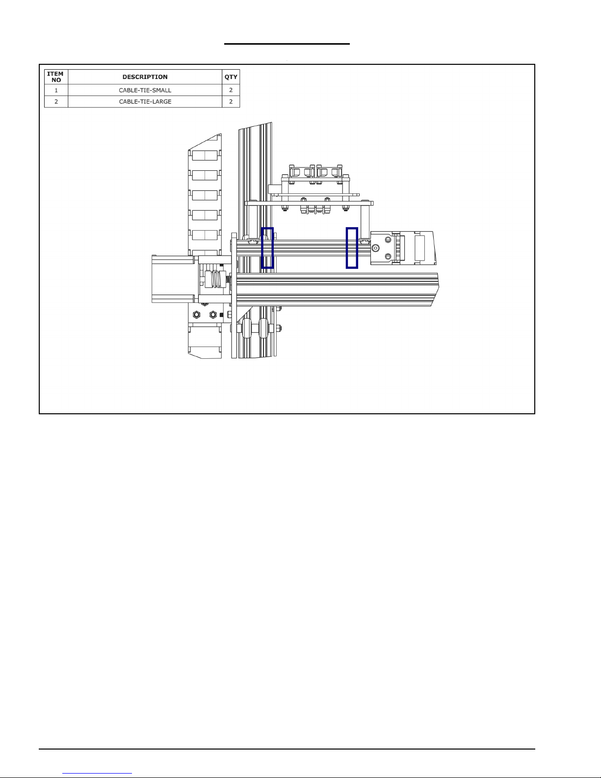
A. Once the machine is operating correctly, using a Cable-Tie-Large secure the wires in
Section 4.2.2 or 4.2.3 to the V-Slot-2040-750mm at the position shown by the right
hand rectangle above. One at a time, the wires can be disconnected from the CNCxPro and trimmed to the correct length.
B. Any excess wire in the PSU-Output-Power-Cables should be pulled out at the 24V-
360W-Power-Supply end and bundled using a Cable-Tie-Large. Use 2 x Cable-TieSmalls secure the PSU-Output-Power-Cables to the slotted holes on the Y-Drag-ChainFixed-End-Mount.
C. Using a Cable-Tie-Large secure the wires in Section 4.2.5 or 4.2.6, and the PSU-Out-
put-Power-Cables to the V-Slot-2040-750mm at the position shown by the left hand
rectangle above. One at a time, the wires can be disconnected from the CNC-xPro and
trimmed to the correct length.
Page 51
WorkBee CNC Wiring & Commissioning 49
6.5 Complete
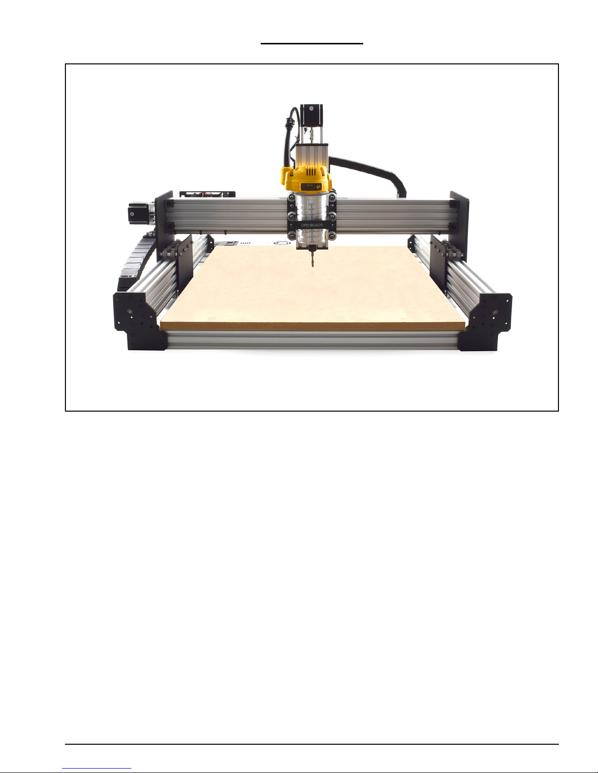
Congratulations! You have completed the Full Kit Assembly of the WorkBee, and we hope
you have enjoyed the build. Below are some general pointers meant to guide you in the
correct direction when using the machine with UGS.
A. In your CAM package it is recommended that you set the working area to the same
size as your intended work piece, and set the zero position to the upper front left corner of the work piece. Export the G-Code file with a GRBL post processor. If a GRBL
post processor isn’t available, select a standard G-Code file with no post processor
and no arcs.
B. In UGS home the machine, and then use the jog commands to position the machine
to the same upper front left corner set in the CAM package.
C. In the ‘Machine Control’ tab press ‘Reset Zero’. This is a crucial step, and must not be
forgotten. This will set the work coordinates to zero, if you need to re-home the
machine for any reason, and press ‘Return to Zero’ it will return to this position.
D. Load your G-Code file in the ‘File-Mode’ tab. Press ‘Send’ to begin the file.
E. It is highly recommended that you use a pen in place of a spindle when first using the
machine, and have a piece of paper as the work piece. This allows you to get used to
the machine in a safe manor. To prevent crushing the pen, work on only one plane in
your CAM package and have no negative Z Movements.
F. Some general pointers - avoid at all times moving the machine around by hand, doing
this can damage the controller or reset settings. Always plug the machine in via USB,
before powering it on. Keep the USB Cable and Spindle out of the cable carriers where
Page 52

WorkBee CNC Wiring & Commissioning 50
possible. If you are having issues, please read through Appendix C before contacting
us.
Page 53

WorkBee CNC Appendix 51
7.0 Appendix
Page 54
WorkBee CNC Appendix 52
7.1 Appendix A - Kit Contents
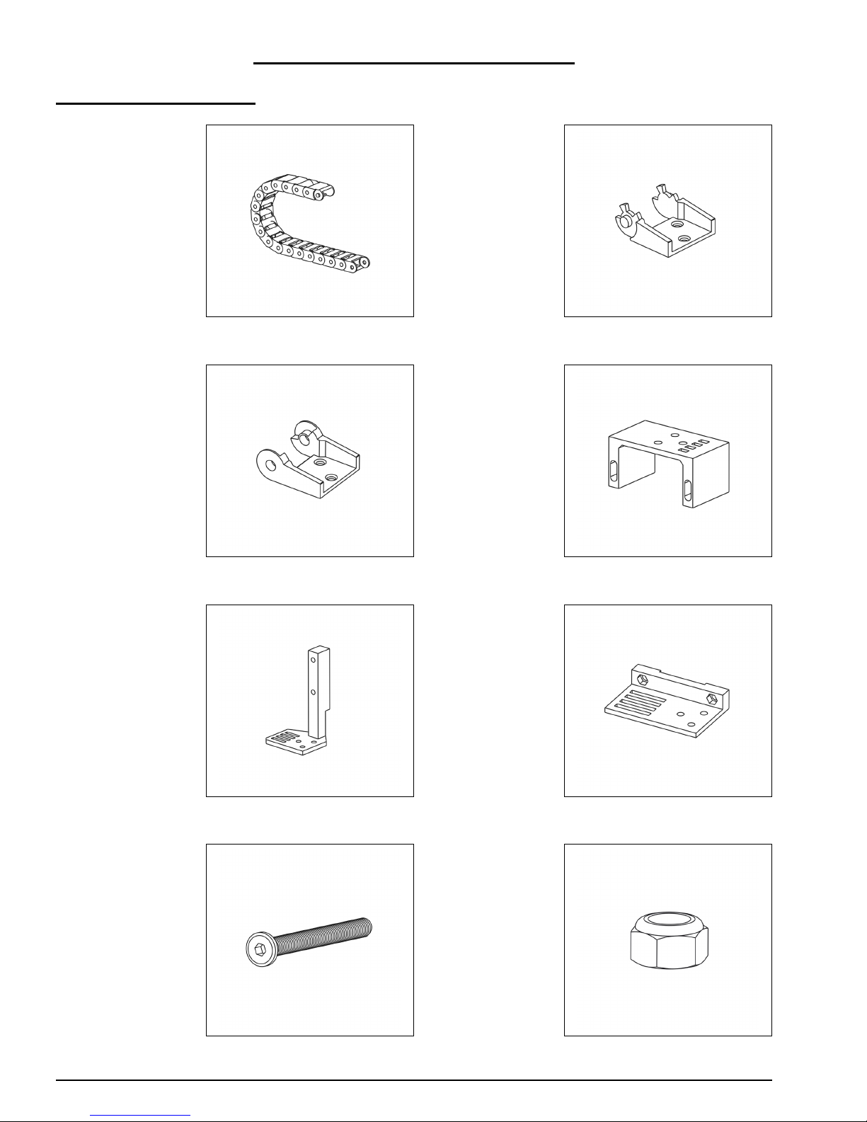
Drag Chains Assembly
1 x X-Drag-Chain
1 x Y-Drag-Chain
2 x Drag-ChainFixed-End
2 x Drag-ChainMoving-End
1 x X-Drag-ChainMoving-End-Mount
1 x Y-Drag-ChainFixed-End-Mount
1 x Y-Drag-ChainMoving-End-Mount
M5-Low-Profile:
1 x 8mm
9 x 15mm
2 x 20mm
2 x 25mm
2 x 55mm
13 x M5-Nyloc-Nut
Page 55

WorkBee CNC Appendix 53
3 x M5-Drop-InTee-Nut
Cable-Tie:
25 x Small
25 x Large
Page 56
WorkBee CNC Appendix 54
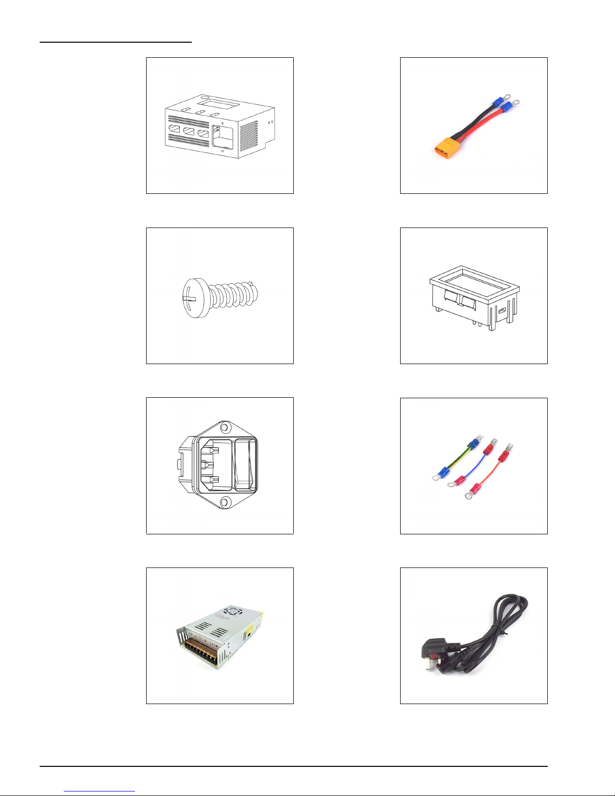
Power Supply Assembly
1 x PSU-Cover 3 x XT60-Male
Plastite-Screws:
6 x M3-8mm
6 x M2.5 x 8mm
1 x LED-Volt-Meter
1 x IEC-Inlet IEC-Inlet-Wires:
1 x Live
1 x Neutral
1 x Earth
1 x 24V-360WPower-Supply
1 x Mains-Cable
Page 57

WorkBee CNC Appendix 55
3 x PSU-OutputPower-Cable
Page 58
WorkBee CNC Appendix 56
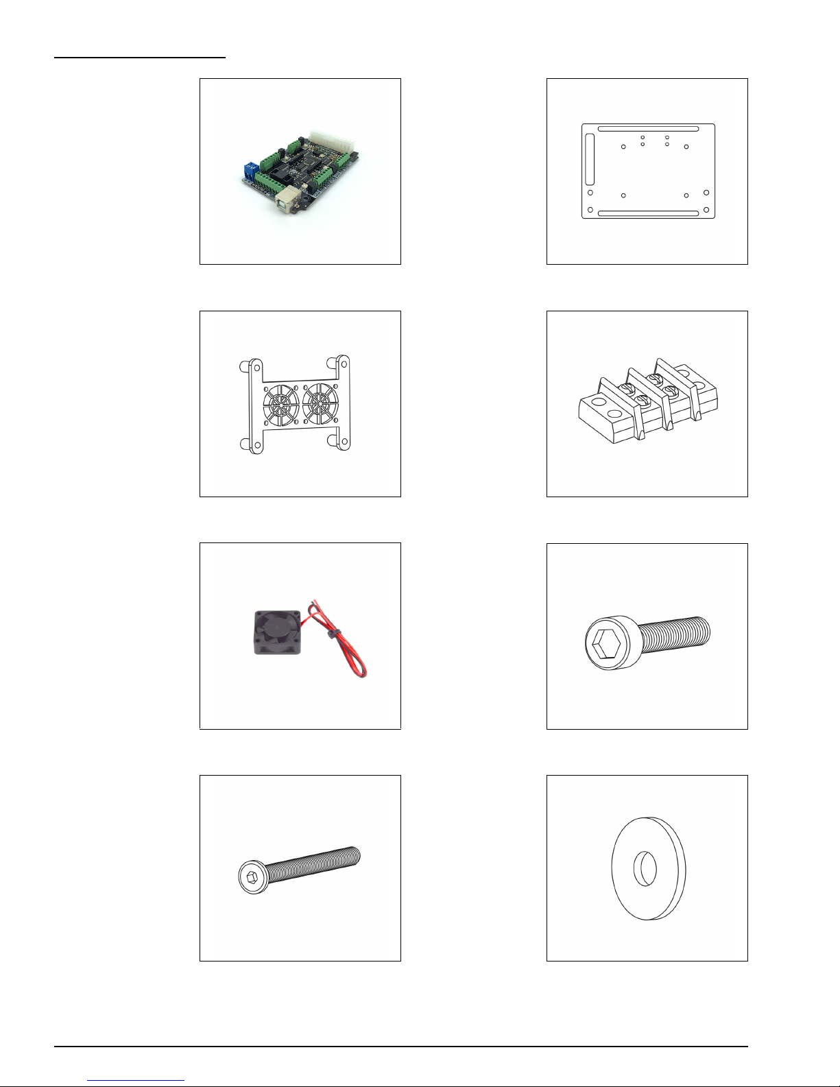
CNC-xPro Assembly
1 x CNC-xPro 1 x CNC-xPro-
Mount
1 x CNC-xPro-FanMount
1 x Terminal-Block
2 x 30mm-24V-DCFan
Cap-Head:
4 x M3-16mm
8 x M3-20mm
4 x M4-40mm
4 x M5-Low-Profile50mm
4 x Slot-Washer
Page 59
WorkBee CNC Appendix 57
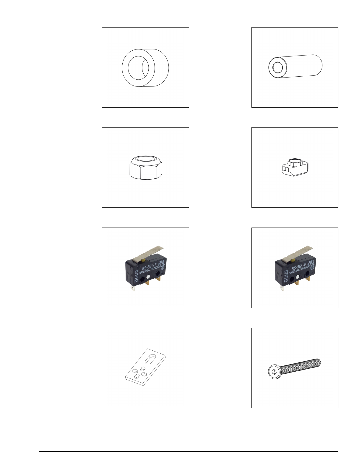
4 x Nylon-SpacerQuarter-Inch
4 x AluminiumSpacer-OneHalfInce
Nyloc-Nuts:
12 x M3
4 x M4
6 x M5-Drop-InTee-Nut
2 x Limit-Switch 1 x Z-Axis-Limit-
Switch (They are
the same as the
Limit-Switch except
the holes are
larger)
2 x Limit-SwitchPlate
2 x M5-Low-Profile8mm
Page 60
WorkBee CNC Appendix 58
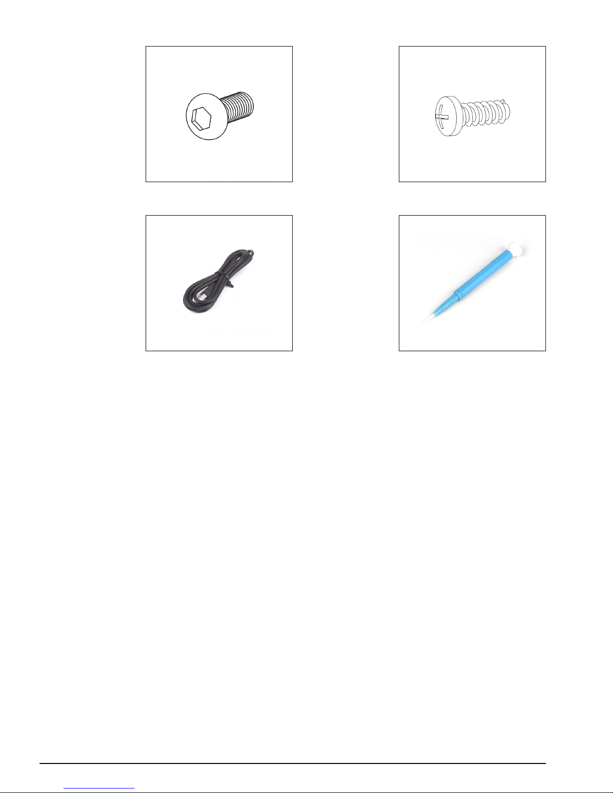
2 x M3-SocketHead-10mm
4 x Plastite-ScrewM3-8mm
1 x USB-Cable 1 x Ceramic-Screw-
Driver
Page 61

WorkBee CNC Appendix B 59
8.0 Appendix B
Page 62
WorkBee CNC Appendix B 60
8.1 Recommended GRBL Settings
The settings below are for a belt driven WorkBee.
Page 63
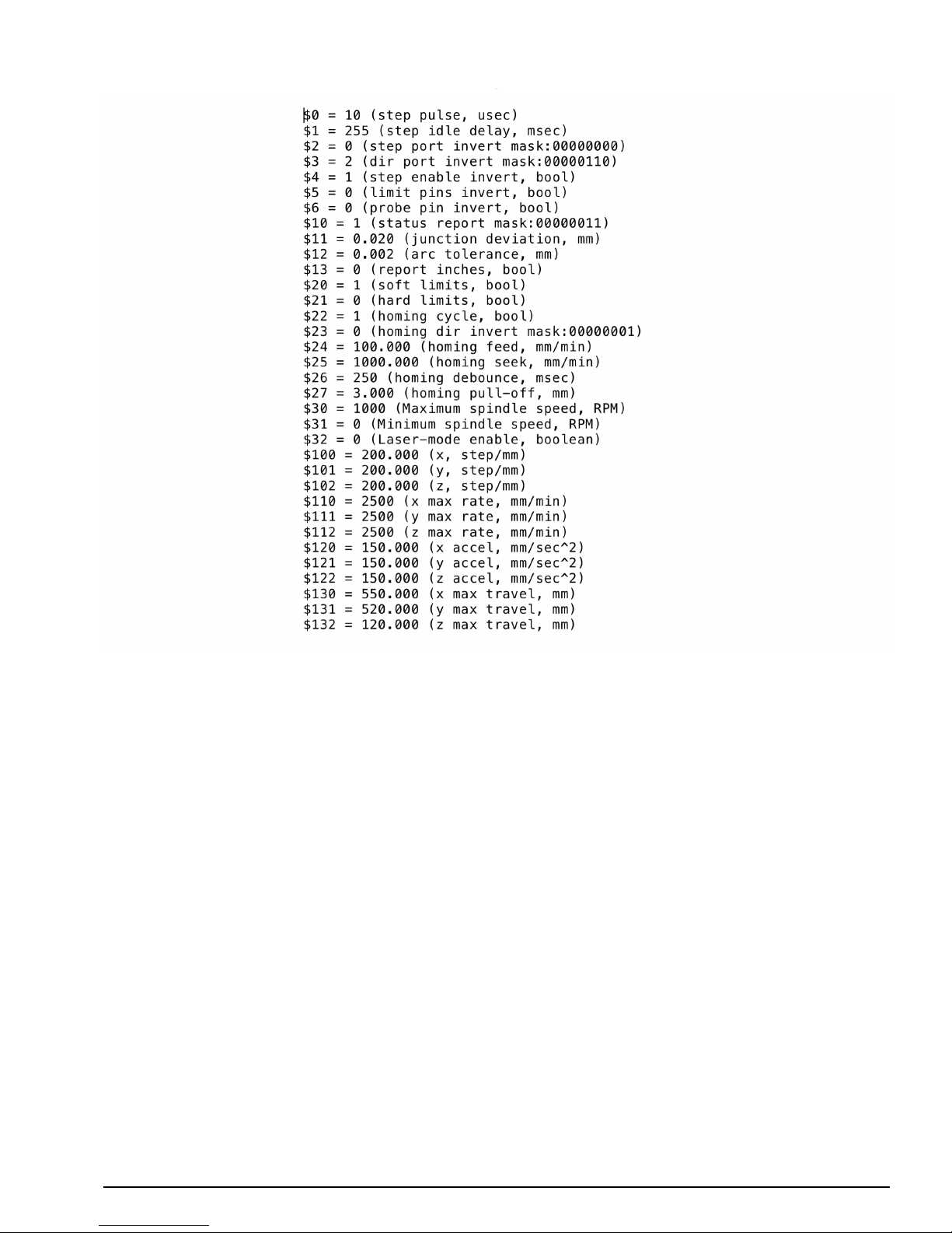
WorkBee CNC Appendix B 61
The settings below are for a screw driven WorkBee.
Page 64
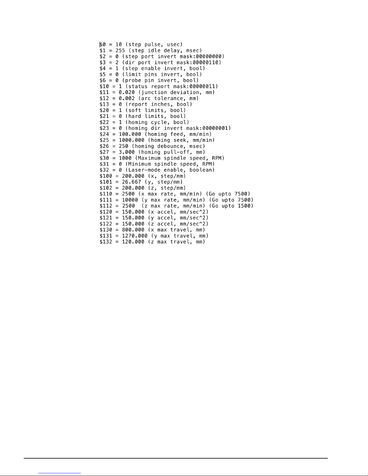
WorkBee CNC Appendix B 62
The settings below are for a belt & screw driven WorkBee.
Page 65
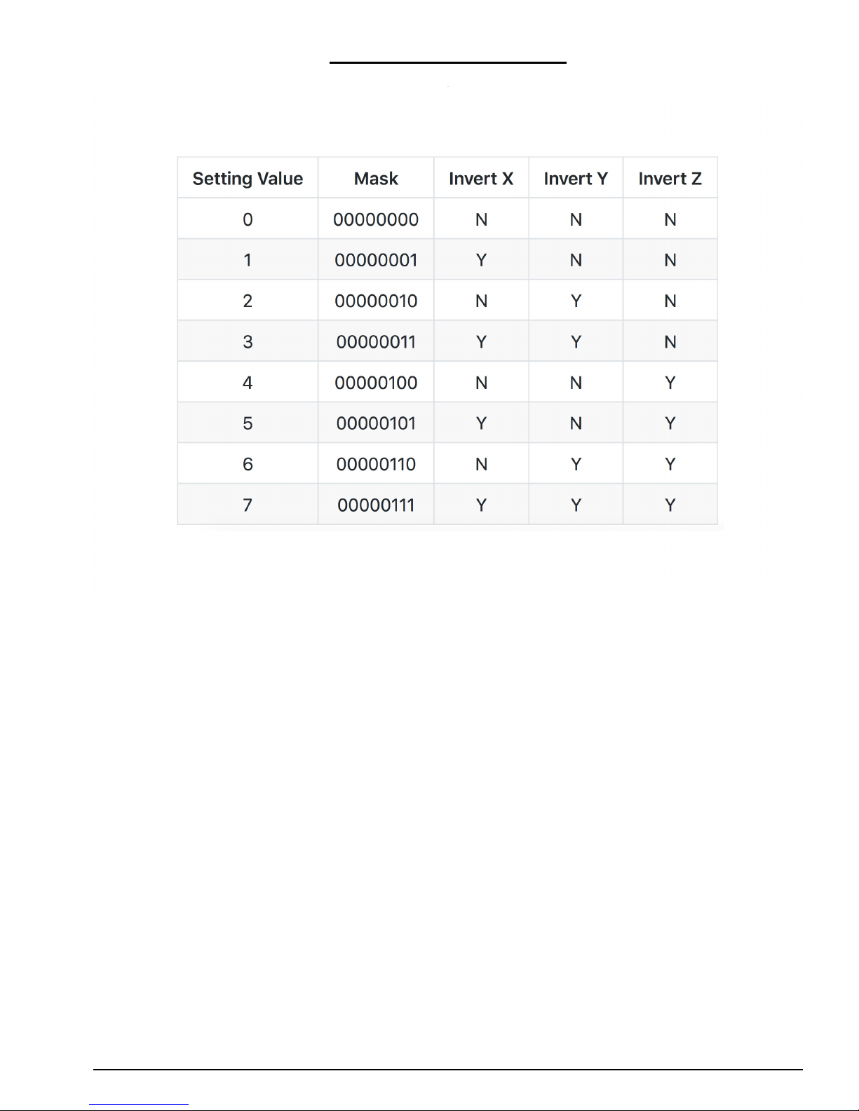
WorkBee CNC Appendix B 63
8.2 Invert Mask Table
Page 66

WorkBee CNC Appendix C 64
9.0 Appendix C
Page 67

WorkBee CNC Appendix C 65
9.1 Common Trouble Shooting Questions
The problems and answers below are the most common issues that we have received in
our experience. If you are having an issue, before contacting us, we recommend reading
through this beforehand.
Problem - LED Volt Meter is not displaying anything.
Check it is wired correctly - if it is wired correctly please email us asking for a replacement and one will be sent out right away.
Problem - Motors are not moving when issuing a jog command.
Check $4 = 1.
Problem - A motor is juddering, but not turning.
This is mostly due to either the motor being wired in an incorrect color order, or there is
a loose wire connection.
Problem - When issuing a Y-Axis jog command, it just vibrates but doesn’t
move.
This is a common error on a belt drive machine, as the motors have to be turning in
opposite directions. Go back through section 6.1, and specifically look at the top right of
the image regarding belt drive wiring.
Problem - Soft limit errors every time when running a file.
Check $130, $131, & $132 are set to the correct value for your size machine. Make sure
the CAM program is setup in millimeters. Make sure that work zero is set in a position
which allows for enough travel on each axis to complete the job. Most CAM programs
have a safe Z Height setting, so make sure there is also enough positive Z travel from
work zero to accommodate this.
Problem - When cutting, circles are not circle.
This is most likely because either a coupler or pulley is slipping on the motor shaft. Check
screws are tight, and one of them is on the flat portion of the motor shaft.
Problem - Machine goes randomly off course mid job or machine stops.
Electrical interference is a common cause of this problem. Make sure the USB & router
cable are outside the drag chains, and sleep/low power mode is turned off on the computer. Carry out a long dummy run with a pen (i.e no router and no dust extraction) and
see if the problem persists. If it still persists, try another computer.
Problem - Machine was working correctly, now suddenly behaving strangely.
Sometimes the $$ settings can change value, this usually happens if the machine is
moved around by hand. Re-check all $$ values to make sure they are set correctly.
Problem - Can’t connect to CNC xPro/GRBL is not loading.
First try another USB Cable. Then try another computer. The last thing to try is resetting
the firmware on the controller. To do this download the Arduino IDE: https://www.arduino.cc/en/Main/Software
Page 68

WorkBee CNC Appendix C 66
Connect the CNC xPro via USB and make sure Universal G-Code sender is closed. Open
the Arduino IDE. In the Arduino IDE set Tools > Board to ‘Arduino/Genuino Uno’. Set
Tools > Port to the port the CNC xPro is connected to. Set Tools > Programmer to
‘AVRISP mkII’
Open Files > Examples > EEPROM > eeprom_clear and then click the upload button
(Second button in from the left, is a arrow pointing to the right) if this gives an error
please contact us. If you get the ‘Done uploading message’ follow these steps to upload
GRBL: https://github.com/grbl/grbl/wiki/Compiling-Grbl
 Loading...