

ooznest Prusa i3 Assembly Manual
Prusa i3
Assembly Instructions
Written By Ryan Lock

Overview
The Prusa i3 is the third iteration in the series of printers designed Josef Prusa, our kit uses his opensource
design and adds many beneficial upgrades. Our Kit includes all the parts required to build a Prusa i3 plus
many extras that will help you to get printing as quick as possible.
What we have done for you
In our kit all plastic parts have been preprepared and checked for fitting. For plastic parts that require nuts
to be inset this has been done, but please check the plastic parts box for any that may have fallen out
during shipping, Instruction Steps marked with a “*” means some of this step has already been done.
All wires that need terminal connectors have been pre-crimped and terminals attached, we have not cut
wires to a certain length so you can do the cable management the way you prefer. Z-Axis motor wires have
been inserted through the holes in the frame
The MK2A Aluminium heated bed has 1metre power wires pre-soldered and the thermistor is preattached.
The Hexagon hot end has been assembled with cartridge heater and thermistor attached, it has been preheated and tightened at 220°C. The Hexagon hot end has also been pre-attached to the Bulldog Lite
Extruder.
Arduino Mega2560, RAMPS 1.4 & Stepper Drivers (Heat sinks still need to be attached) are pre-assembled
and flashed with pre-configured firmware, the output current on the stepper drivers have also been set.
Notes on assembly
Using Appendix A check that all parts have been supplied and no parts have been damaged during
shipping, if there is any problems contact us and we will rectify the issue as quick as possible.
It is recommended to read through the instructions thoroughly before starting assembly.
Insure you have a clear, firm and level table to assemble the printer on and you are using tools safely, also
take extreme caution when wiring electronics.
Most washers have a flat side and a rounded side, it is recommended to put the flat side against the plastic
part. Take care to not over tighten the Nuts & Bolts that are in contact with plastics parts because they may
crack.
Any problems contact us (Details on our website) and we will help to resolve the problem.
Most importantly take your time and have fun!
Tools Required
●
Allen Keys (Supplied with kit)
●
5.5/7.0mm Spanners (M3/M4 Nuts)
●
2 x 13/17mm Spanners or 2 x Adjustable Spanners (M8/M10 Nuts)
●
Pliers (Preferably Long Nose)
●
Mallet or Hammer
●
Large & Small Philips Screw Driver
●
Ceramic Screw Driver (Supplied with kit)
●
Tweezers
●
Scissors
●
Ruler
2 of 61

Y-Axis Idler Assembly
Instructions
A)* Insert a M4-Hex-Nut into the inset provided on the backside of the Y-Axis-Idler, screw a M4-20mm-Bolt
through the M4-Hex-Nut Nut until it is just about to come through the other side of the M4-Hex-Nut.
B) Screw a M3-25mm-Bolt through 2 x 623zz-Flanged Bearings, as in the diagram, insuring that two M3Washers are included. Attach a M3-Nyloc-Nut and tighten the M3-25mm-Bolt, once tight insure the
bearing assembly rotates freely.
3 of 61

A) Thread M8-Hex-Nuts, M8-Washers, Y-Axis-Idler & Y-Axis-Corner's along the 2 x Threaded-Rod-8mm in
the order as shown in the diagram.
B) Finger tighten the M8-Hex-Nuts so the Y-Axis-Idler and Y-Axis-Corners are as shown in the left hand
image. Make sure the 8mm-Threaded-Rod is touching the backside of elongated hole on the Y-Axis-Idler
when tightening the nuts either side of it. All Nuts will be fully tightened at a later stage.
Instructions
4 of 61
Y-Axis Front Assembly
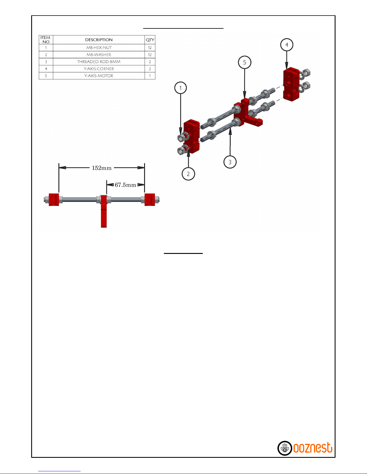
A) Thread M8-Hex-Nuts, M8-Washers, Y-Axis-Motor & Y-Axis-Corner's along the 2 x Threaded-Rod-8mm in
the order as shown in the diagram.
B) Finger tighten the M8-Hex-Nuts so the Y-Axis-Idler and Y-Axis-Corners are as shown in the left hand
image. Make sure the Y-Axis-Motor is perpendicular to both Threaded-Rod-8mm when tightening the nuts
either side. All Nuts will be fully tightened at a later stage.
Y-Axis Back Assembly
Instructions
5 of 61
Instructions

A)* Insert M3-Nyloc-Nuts into each of the Hex insets on the 4 Heated-Bed-Spring-Traps. Push a HeatedBed-Spring-Trap onto each of the corners on the Y-Axis-Bed-Plate
B) Attach the Y-Axis-Belt-Holder to the Y-Axis-Bed-Plate using 2 x M3-16mm-Bolts & 2 x M3-Nyloc-Nuts,
insure you place a M3-Washer in-between each M3-16mm-Bolt head and the Y-Axis-Belt-Holder, make
sure the Y-Axis-Belt-Holder is straight before fully tightening the bolts.
C) On each Y-Axis-Bearing-Holder insert a cable tie through each of the 2 provided slots so it goes in on the
side the bearing will sit then the whole way under the bearing holder and comes back out on the same
side, do not tie them up.
D) Insert a LM8UU-Bearing into each Y-Axis-Bearing-Holder, attach each Y-Axis-Bearing-Holder to the
Y-Axis-Bed-Plate using 2 x M3-30mm-Bolts & 2 x M3-Nyloc-Nuts, make sure they are straight before fully
tightening the bolts. For the 2 x Y-Axis-Bearing-Holders on the left hand side it is recommended to
temporarily insert any one of the 8mm-Smooth-Rods through the two LM8UU-Bearings while tightening
the bolts to insure the LM8UU-Bearings are centred on each other.
E) The cable ties previously inserted can now be used to securely attach the LM8UU-Bearings to the Y-AxisBearing-Holders, if available use pliers to firmly pull the cable ties. The 8mm-Smooth-Rod can now be
removed.
Y-Axis Bed Assembly
6 of 61
Instructions
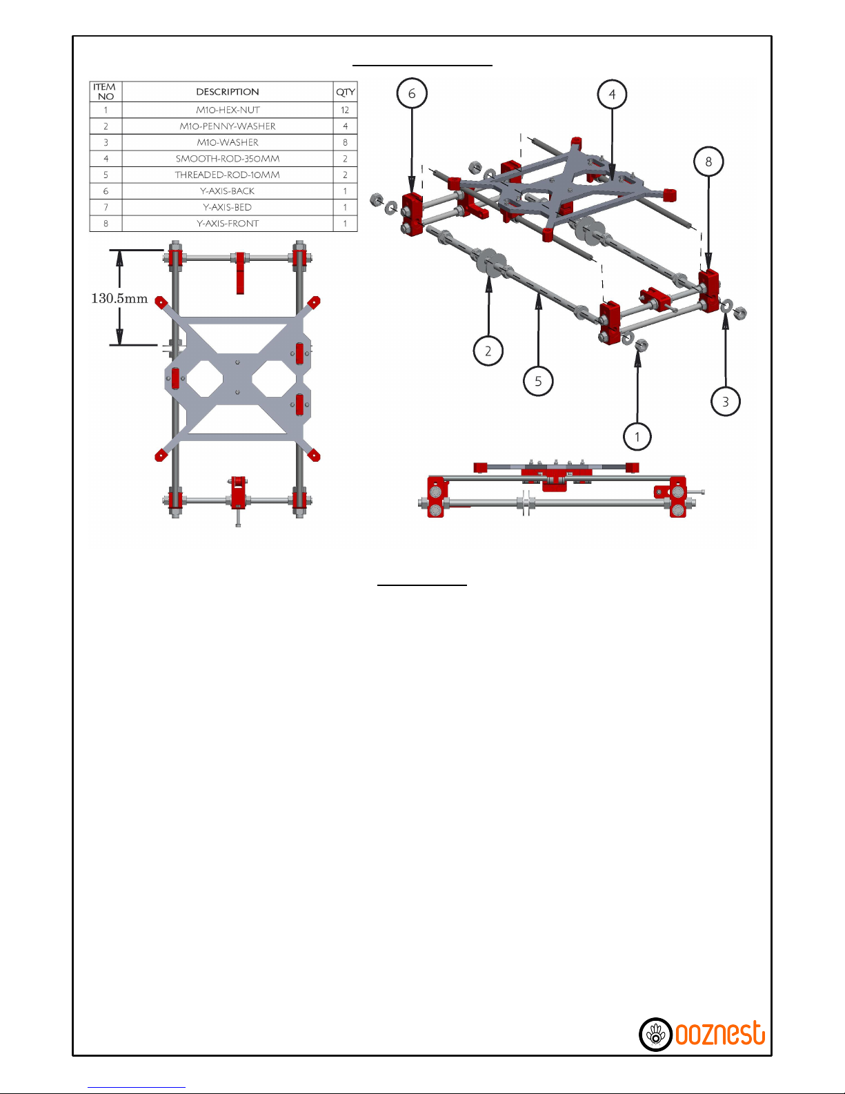
A) Thread M10-Hex-Nuts, M10-Washers, M10-Penny-Washers, Y-Axis-Front & Y-Axis-Back on to both
Threaded-Rod-10mm in the order as shown in the diagram.
B) Insert 2 x Smooth-Rod-350mm through the LM8UU-Bearings of the previously assembled Y-Axis-Bed,
then insert the ends of the Smooth-Rod-350mm into the insets on the Y-Axis-Corners, make sure the side
on the Y-Axis-Bed with one LM8UU-Bearing is on the left hand side of the assembly. Insure the ends of the
Smooth-Rod-350mm are touching the ends of all 4 insets on the Y-Axis-Corners.
C) Tighten the whole assembly including the M8-Hex-Nuts on the Front and Back Side's (Except from the
M8-Hex-Nuts either side of the Y-Axis-Idler). All 4 Y-Axis-Corner's should be touching the ground, if not to
diagnose individually check all 4 Y-Axis-Corner's after tightening each bolt and recheck distances between
the Y-Axis-Corners on the Front & Back Sides. Make sure both Smooth-Rod-350mm cannot move forward
or backwards, but can still be lifted out of the insets.
D) Check that the motion of the Y-Axis-Bed is smooth, if not recheck the distances between the Y-Axis
Corners on the Front & Back Sides.
E) The M10-Penny-Washers should be roughly 130.5mm from the back side as shown in the right hand
picture, these will be tightened against the Z-Axis-Frame Later.
F) At this point do not zip tie down the Smooth Rods.
Y-Axis Assembly
Instructions
7 of 61
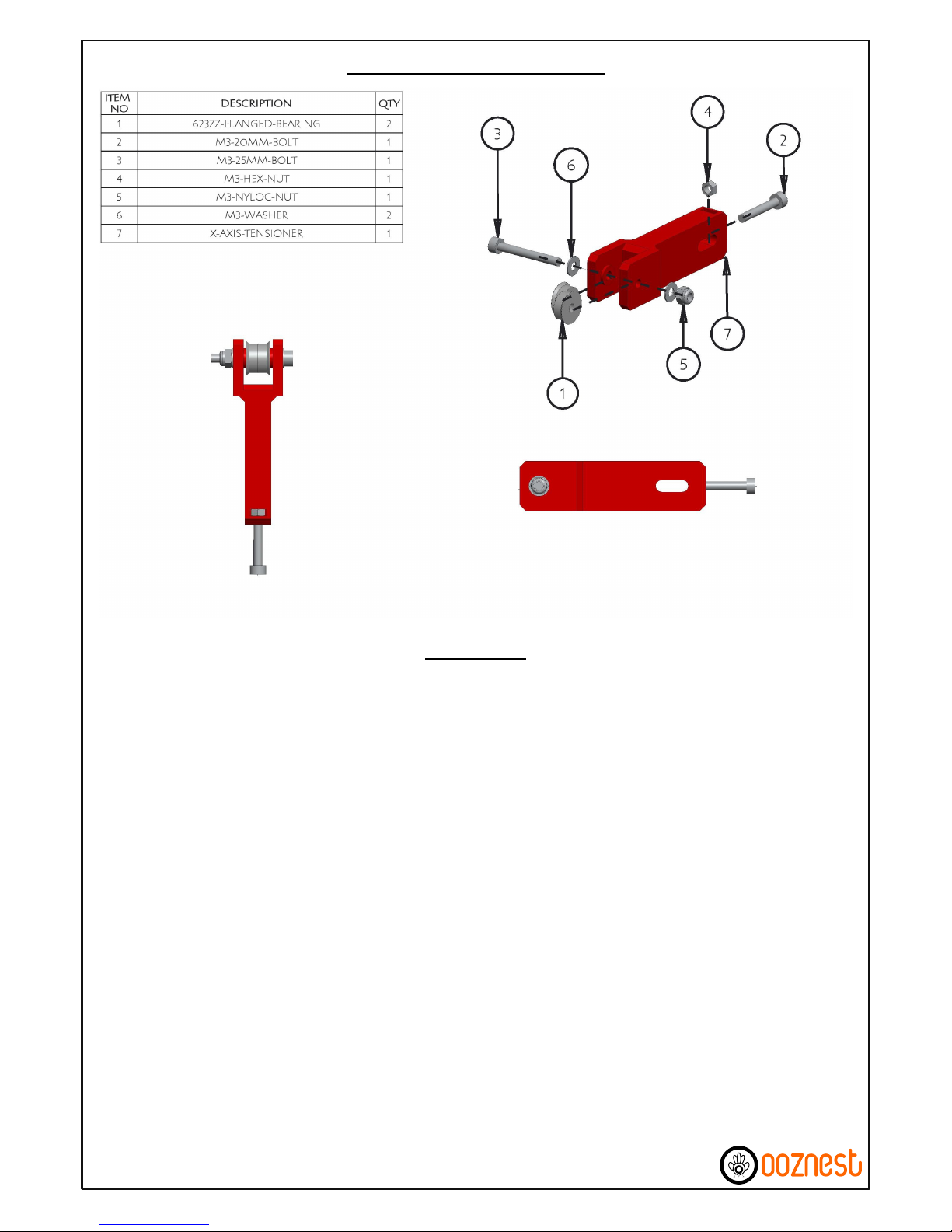
A) Insert A M3-Hex-Nut into the inset provided on the backside of the X-Axis-Tensioner, screw a M3-20mmBolt through the M3-Hex-Nut until it is just about to come through the other side of the M3-Hex-Nut.
B) Screw a M3-25mm-Bolt through 2 x 623zz-Flanged Bearings, as in the diagram, insuring that two M3Washers are included. Attach a M3-Nyloc-Nut and tighten the M3-25mm-Bolt, once tight insure the
bearing assembly rotates freely.
X-Axis Tensioner Assembly
Instructions
8 of 61
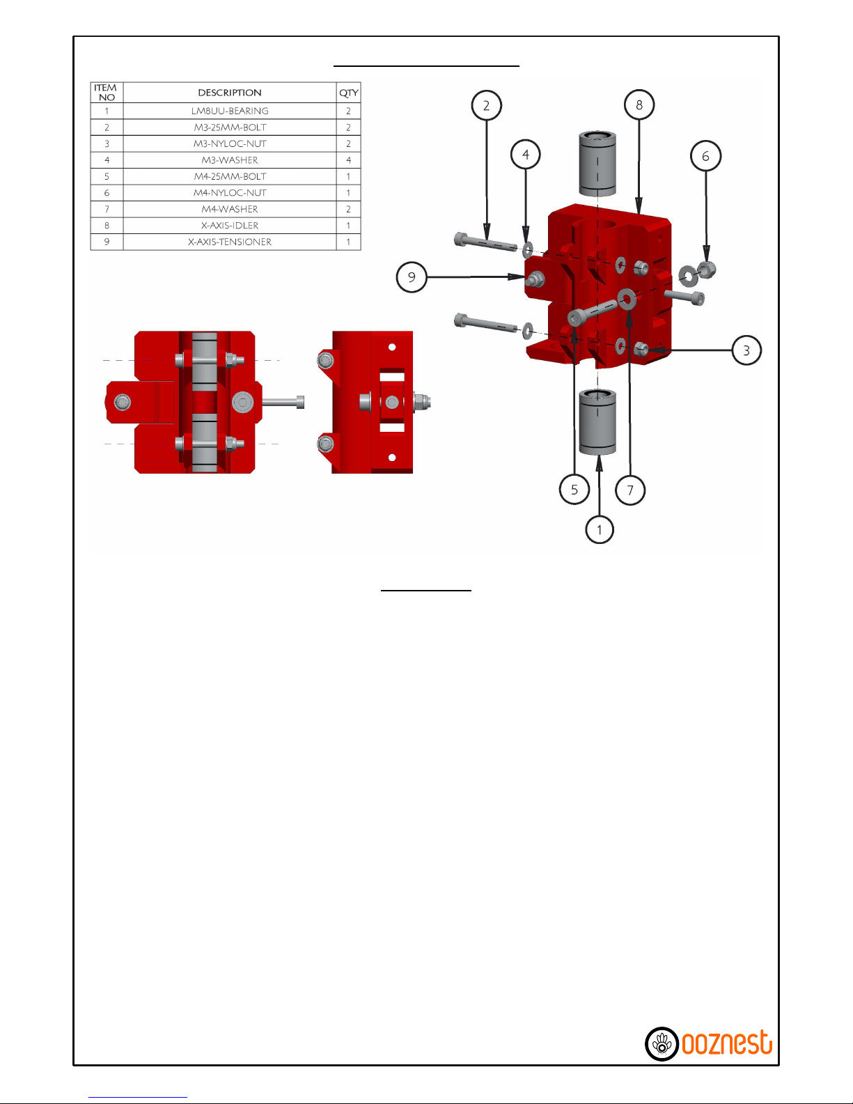
A) Insert the X-Axis-Tensioner through the horizontal slot in the X-Axis-Idler as shown above. Screw a M425mm-Bolt through the X-Axis-Idler & X-Axis-Tensioner remembering to include the M4-Washers, then
attach a M4-Nyloc-Nut and finger tighten, this will be fully tightened later on once the GT2-Belt has been
connected.
B) Push a LM8UU-Bearing into the top & bottom slots of the X-Axis-Idler, clamp each LM8UU-Bearing in
position using a M3-25mm-Bolt, 2 x M3-Washers & M3-Nyloc-Nut. Before tightening the M3-25mm-Bolt's
insert a 8mm-Smooth-Rod through both LM8UU-Bearings to insure they are centred on each other, make
sure the bearings are flush with the top & bottom surfaces on the X-Axis-Idler. Only slightly tighten the M325mm-Bolt's otherwise the 8mm-Smooth-Rod will no longer ride smoothly through the LM8UU-Bearings.
The 8mm-Smooth-Rod can now be removed.
X-Axis Idler Assembly
Instructions
9 of 61
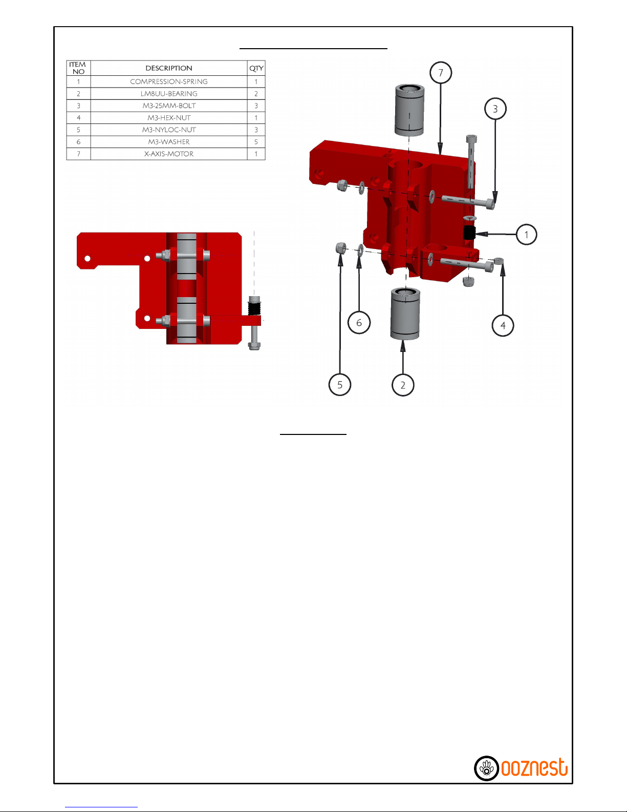
A)* Insert a M3-Hex-Nut into the slot provided on the right hand side of the X-Axis-Motor. Screw a M325mm-Bolt through a M3-Washer & Compression Spring, once through the other side attach a M3-NylocNut to the end. While holding the M3-Nyloc-Nut with a spanner screw the M3-25mm-Bolt until it is flush
with the bottom of the M3-Nyloc-Nut. The M3-20mm-Bolt will be adjusted later to trigger the MechanicalEndstop.
B) Push a LM8UU-Bearing into the top & bottom slots of the X-Axis-Motor, clamp each LM8UU-Bearing in
position using a M3-25mm-Bolt, 2 x M3-Washers & M3-Nyloc-Nut. Before tightening the M3-25mm-Bolt's
insert a 8mm-Smooth-Rod through both LM8UU-Bearings to insure they are centred on each other, make
sure the bearings are flush with the top & bottom surfaces on the X-Axis-Motor. Only slightly tighten the
M3-25mm-Bolt's otherwise the 8mm-Smooth-Rod will no longer ride smoothly through the LM8UUBearings. The 8mm-Smooth-Rod can now be removed.
X-Axis Motor Assembly
Instructions
10 of 61
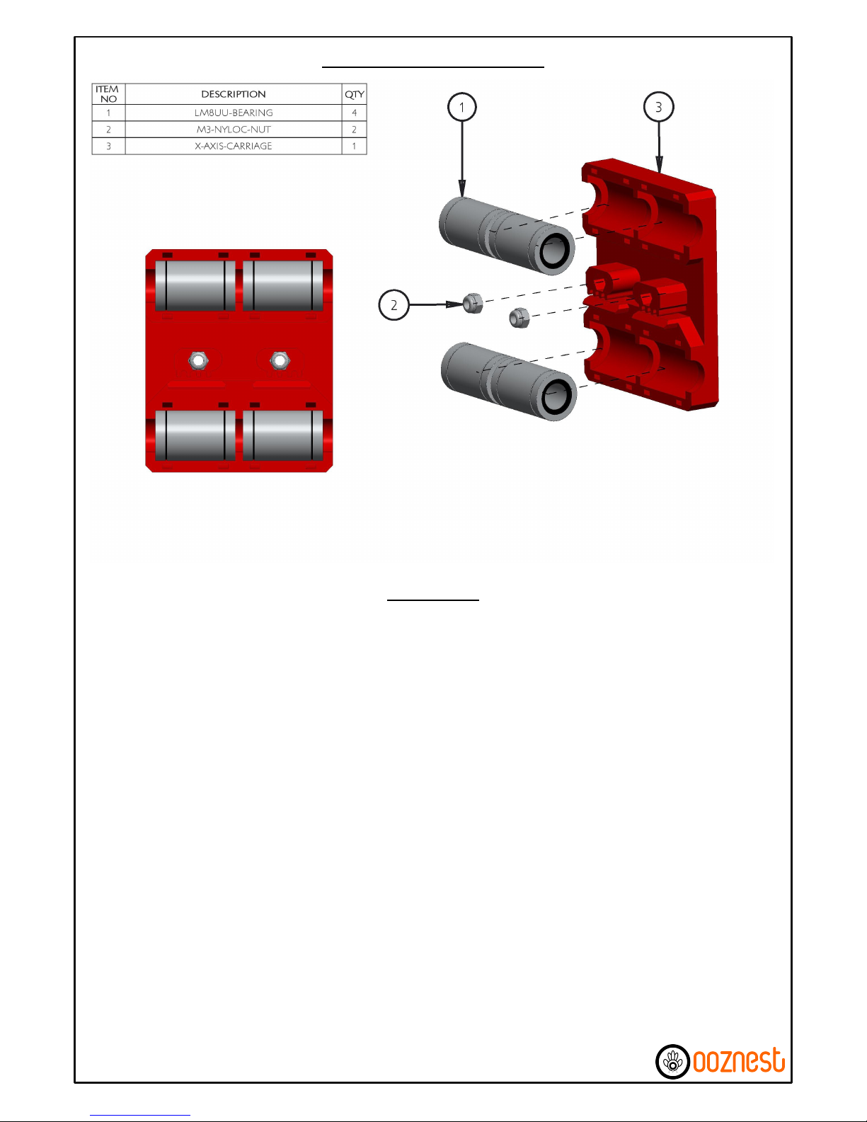
A) Insert 4 x LM8UU-Bearings into the bearing holders on the X-Axis-Carriage. Insert a 8mm-Smooth-Rod
through each pair of LM8UU-Bearings and securely attach each LM8UU-Bearing to the X-Axis-Carriage
using cable ties through the provided slots, the 8mm-Smooth-Rods can now be removed.
B)* Push 2 x M3-Nyloc-Nuts into the insets provided.
X-Axis Carriage Assembly
Instructions
11 of 61
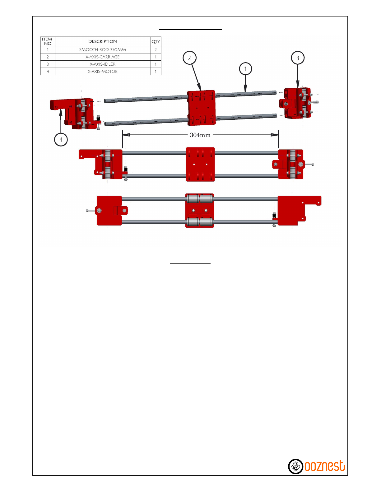
A) Push a Smooth-Rod-370mm into each hole on the X-Axis-Motor, insure they are fully seated, lightly tap
with a hammer if needed.
B) Slide the X-Axis-Carriage onto the 2 x Smooth-Rod-370mm, it should be oriented so the teeth on the
back of the X-Axis-Carriage are pointing downwards.
C) Push the X-Axis-Idler onto the 2 x Smooth-Rod-370mm, once fully seated the distance between the XAxis-Idler and X-Axis-Motor should be 304mm.
X-Axis Assembly
12 of 61
Instructions
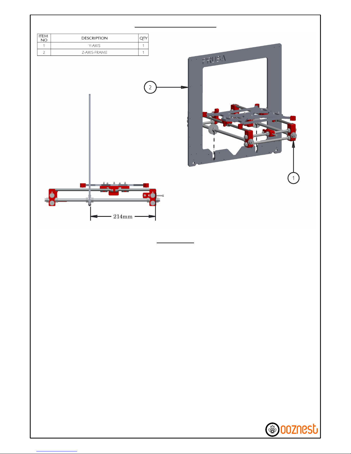
A) Insert the Z-Axis-Frame Between the M10-Penny-Washers on the Y-Axis.
B) Adjust the Z-Axis-Frame so the distance between the front side of the Z-Axis-Frame and the end of the
Smooth-Rod-350mm is 214mm on both sides.
C) Strongly tighten the 4 x M10-Hex-Nuts that are holding the Z-Axis-Frame. Access to these nuts can be
improved by removing the Y-Axis-Bed, this can be done by lifting the M8-350mm-Smooth-Rods out of their
insets on the Y-Axis-Corner's.
Attaching Z-Axis Frame
13 of 61
Instructions
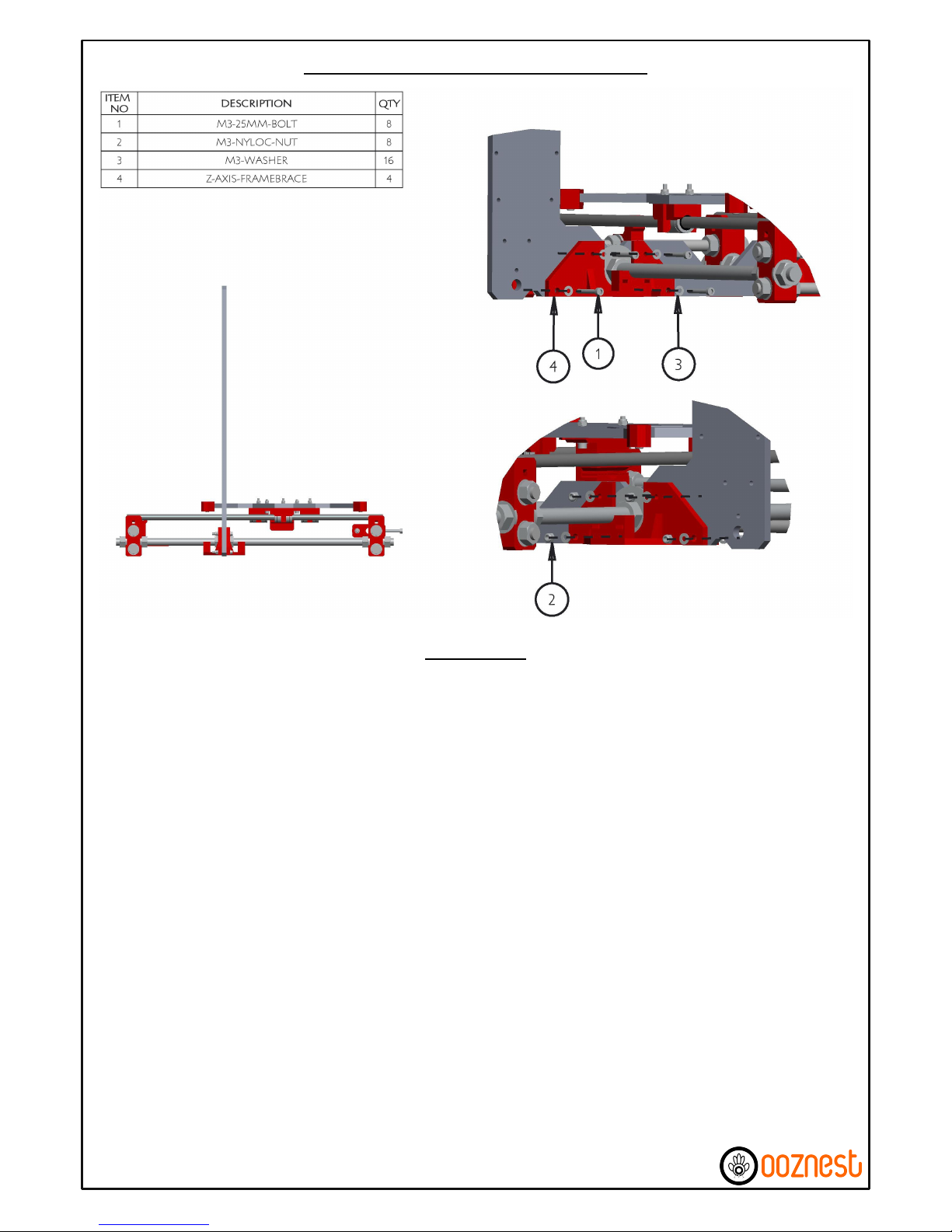
A) Attach a Z-Axis-Framebrace either side of the Z-Axis-Frame on top of the left hand M10-Penny-Washers.
This is done using 4 x M3-25mm-Bolts, 8 x M3-Washers & 4 x M3-Nylocs. The M3-25mm-Bolts go through
both Z-Axis-Framebrace's with the M3-Nylocs attaching on the backside.
B) Follow the same procedure to attach the 2 x Z-Axis-Framebrace's over the right hand M10-PennyWashers.
Z-Axis Frame Brace Assembly Part 1
14 of 61
Instructions
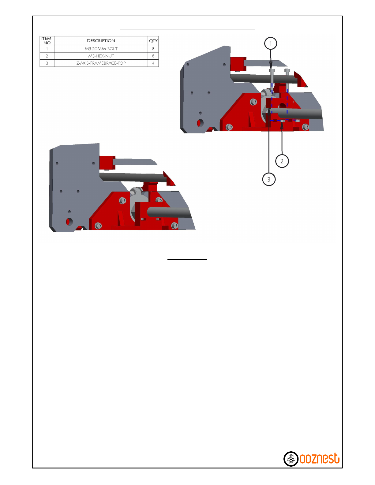
A)* Insert a M3-Hex-Nut into each of the 2 slots provided on the Z-Axis-Framebrace.
B) Place the Z-Axis-Framebrace-Top over the Threaded-Rod-10mm and tighten down into the inserted M3-
Hex-Nut using 2 x M3-20mm-Bolts.
C) Repeat the process on the other three Z-Axis-Framebrace's.
Z-Axis Frame Brace Assembly Part 2
15 of 61
Instructions
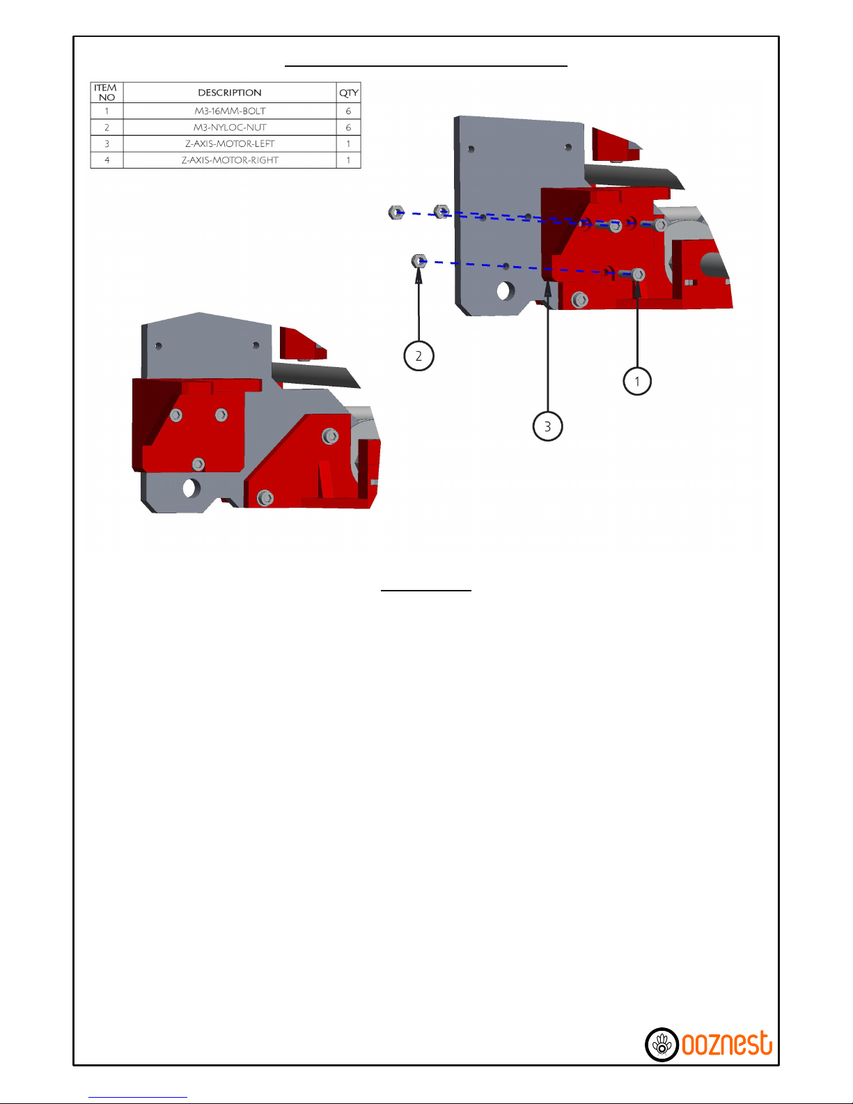
A) Attach the Z-Axis-Motor-Left using 3 x M3-16mm-Bolts and 3 x M3-Nyloc-Nuts.
B) Repeat the process for Z-Axis-Motor-Right.
Z-Axis Motor Mount Attachment
16 of 61
Instructions
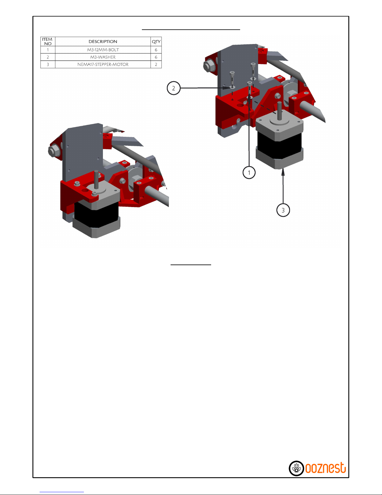
A) Attach a NEMA17-Stepper-Motor to the Z-Axis-Motor-Left using 3 x M3-12mm-Bolts and 3 x M3Washers. Make sure that the connection terminal on the NEMA17-Stepper-Motor goes against the frame,
and connect the wire that has been pre-inserted through the hole to this terminal.
B) Repeat the process to attach the NEMA17-Stepper-Motor to the Z-Axis-Motor-Right.
Z-Axis Motor Attachment
17 of 61
Instructions
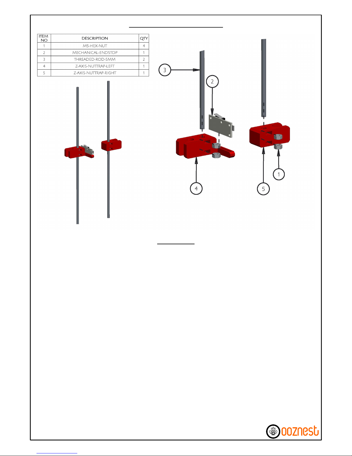
A)* Insert a Brass M5-Hex-Nut in both of the 2 slots on each Z-Axis-Nuttrap, the 2 x M5-Hex-Nuts need to
be in sync for the Threaded-Rod-5mm to go through, this has already been done by us, however the
procedure to get the 2 x M5-Hex-Nuts in sync is detailed in Appendix B.
B) Push a Mechanical-Endstop in the slot provided on the Z-Axis-Nuttrap-Left in the orientation shown in
the diagram, it should go down as far as possible.
C) Thread an assembled Z-Axis-Nuttrap onto each Threaded-Rod-5mm until approximately half way up.
Z-Axis Nut Traps Assembly
18 of 61
Instructions

A)* Insert a M3-Nyloc-Nut into each of the 4 inserts on the Z-Axis-Coupling-Nut-Side.
B) Get the previously assembled Threaded-Rod-5mm & Z-Axis-Nuttrap-Left inline with & touching the top
of the left hand side NEMA17-Stepper-Motor Shaft. Bring the Z-Axis-Coupling-Nut-Side & Z-Axis-CouplingBolt-Side together around the Threaded-Rod-5mm & NEMA17-Stepper-Motor Shaft so half is contact with
the Threaded-Rod-5mm & Half in contact with the NEMA17-Stepper-Motor Shaft. Use 4 x M3-12mm-Bolts
to tighten the Z-Axis-Coupling around the Threaded-Rod-5mm & NEMA17-Stepper-Motor Shaft. The M312mm-Bolts should be as tight as possible.
C) Repeat the same procedure to attach the Threaded-Rod-5mm & Z-Axis-Nuttrap-Right to the right hand
side NEMA17-Stepper-Motor Shaft.
Attaching Threaded Rod to Motor Shaft
19 of 61
Instructions
 Loading...