

Oosec OSE-201, OSE-301 Ie Users Manual
OSE-201/301 IE User’s Manual
Product: OSE-201/301
Document: IE User’s Guide
Published: August 01, 2006
Version: 1.10
Web:
Service Email: service@oosec.com
Copyright © 2006 TWSAFE Corp., All rights reserved.
http://www.oosec.com

Table of Contents
1. Safety Warning
2. FCC Class A Statement
3.
Product Brief Introduction………………………………………….3
Product…………………………….……….…………………….…...4
1.1 Software..…………………….…………………………………..5
1.2 System Reference Structure….…………………………………..5
1.3 Required Additional Accessories ………………………………..6
1.4 Functions………………………….……………………………...7
1.5 Hardware Installation……..………………………………..…….9
2. IP Address Setup
2.1 Hardware Installation.…………………………………………..10
2.2 Network and Internet Connections...………………………..…..11
3. Network Security Setup
3.1 Security/Trusted Sites…………………………………………..14
4. OOSEC Browser
4.1 Login Authentication……………………………………………19
4.2 IE Main Page…………...……………………………………….21
4.3 Real-time Images Display………………………………………22
4.4 Pan-tilt-zoom Control Panel…………………………………….23
4.5 Configuration……………………………..………………….....25
4.5.1 System…………………………………………………….26
4.5.2 Video……………………………………………….……..26
4.5.3 Network…………………………………………………...27
4.5.4 User……………………………………………………….29
4.5.5 Pan-tilt-zoom…………………………..………………….30
4.5.6 Event…………………………………….………………...31
4.5.7 Email………………………………...………….………...32
4.5.8 Log…………………….………………………………….33
4.5.9 Back to Home………………………...…………………...34
Appendix A DDNS Service.…………………..……………………...35
Appendix B Intellectual Property Right………………….…………..44
Appendix C Limited Warranty …………………..…………………...45
Appendix D NTSC/PAL Country/Region List……………………….47
……………………………………………………1
………………………………………….2
2

Safety Warning
z To reduce probable risk of fire or electronic shock, do not expose
this product under rain or moisture environment.
z Remove power before unit installation.
z Please make sure powers of all devices have been unplugged
before connecting to this product.
z Recommend using appropriate power adapter for product safety.
z Please do not tear down this unit for safety and warranty.
z Recommend read this manual thoroughly before system/unit
installation.
z Make sure all cables and power have been successfully installed
on this product.
z Dust, moisture, and dramatic temperature change can cause
mal-function of this unit. Manufacturer advises not to put this
product under these environments.
z If item of this pack is missing or defect of this unit, please contact
certified distributor or reseller for service/maintenance.
3

FCC Class A Statement
Note: This equipment has been tested and found to comply with the limits for a
Class A digital device, pursuant to Part 15 of the FCC Rules. These limits are
designed to provide reasonable protection against harmful interference when the
equipment is operated in a commercial environment. This equipment generates,
uses, and can radiate radio frequency energy and, if not installed and used in
accordance with the instruction manual, may cause harmful interference to
radio communications. Operation of this equipment in a residential area is likely
to cause harmful interference, in which case the user will be required to correct
the interference at his/her own expense.
Properly shielded and grounded cables and connectors must be used in order to
meet FCC emission limits. TWSAFE Inc. is not responsible for any radio or
television interference caused by using other than recommended cables and
connectors or by unauthorized changes or modifications to this equipment.
Unauthorized changes or modifications could void the user's authority to operate
the equipment.
This device complies with Part 15 of the FCC rules. Operation is subject to the
following two conditions: (1) this device may not cause harmful interference, and
(2) this device must accept any interference received, including interference that
may cause undesired operation.
4
Quick Installation Guide (QIG)
The purpose of this QIG is to guide you to go through setup procedure of this
system smoothly in order to view remote video images of video server on IE.
Details of setup functions on IE Web pages and management software of
multi-camera can be seen on User’s Manual.
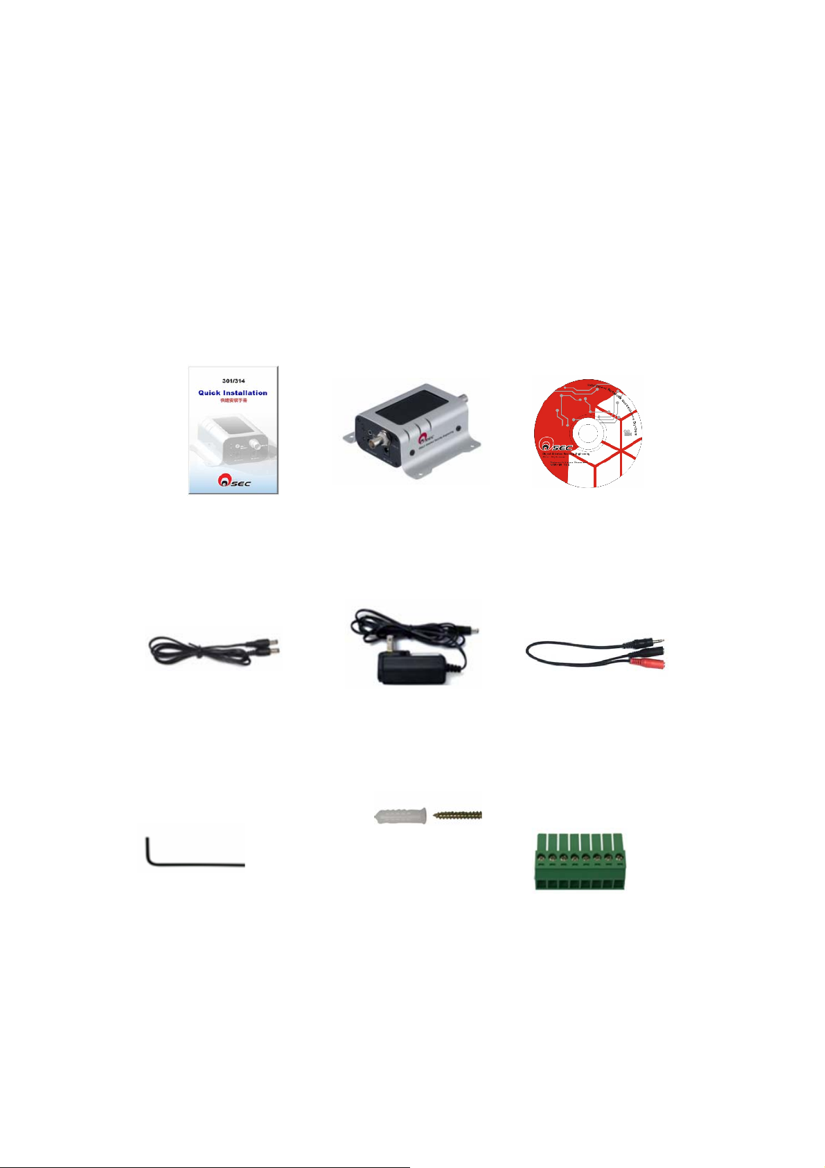
Product & Accessories
Please check packing contents thoroughly after opening this pack.
Contact your reseller while item is missing.
Quick Installation Guide
DC Power
Output
(DC 12V)
OSE-301*1
Adapter*1
Software CD
ROM*1
Microphone/Speaker 2
in1cable*1
Screws *4
L type
wrench*1
I/O Connector*1
5

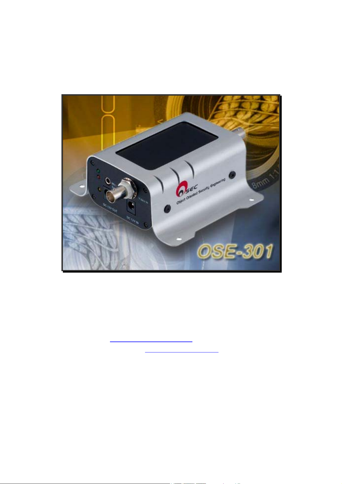
Product Brief Introduction
I. Product
z OSE-301 (301) video server is a device which transforms
analog images into digital through MPEG 4 video
compressed, and transmits images/data via Internet or
Intranet with 2-way audio.
z 301 is an independent web server which user can view via
Internet Explorer everywhere where Internet is connected.
z 301 is equipped with motion detection which can detect,
send alarm, take snapshot while event is triggered.
z 301 has 2 digital inputs and 1 digital output which can
successfully integrate with other security devices e.g.
alarm, light, sensor for better security protection.
z 301 offers an analog video output for on-site clearer
camera images installation and monitoring.
z 301 supports additional DC-12V power output (max. 750
mA) to connect camera or other security device power
input without finding another power source.
z 301 provides RS-485 connectors for pan-tilt device or
speed dome camera surveillance.
II. IE Browser & Multi-port Software
z User can view and monitor video images through IE
Browser without installing any additional software.
z OOSEC Brower offers user for remote video surveillance
and control/setup this product via IE Browser.
z User can use OOSEC Brower to setup network protocols
including IP address environment (DHCP, fixed IP,
PPPoE, and DDNS).
z This pack also attaches 16-port management software for
recording and retrieving recorded images.
6
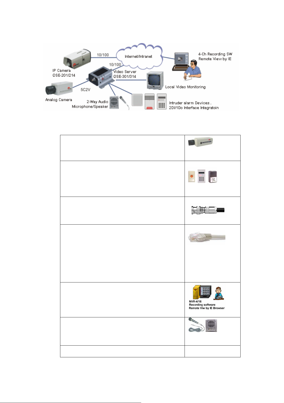
1.1 System Reference Structure
1.2 Required Additional Accessories
y CCD Camera & Accessories: camera,
pan-tilt devices, housing, and bracket
CCD camera*1
y Alarm/Access control: DI/DO to
connect urgent button, sensor, buzzer,
system for security integration.
y Coaxial cable: 5C2V (BNC connector)
cable to connect CCD camera.
y UTP cables: Prepare a parallel UTP
cable with RJ45 connectors to connect
network equipment e.g. switch/hub, IP
sharing, router. Use a cross-over cable
if directly connects to PC.
y 16-port Recording Requirement: CPU
Intel P4 3.2, 1G memory, 128 MB
Alarm (option)
5C2V coaxial cable
RJ45 UTP cable
VGA, OS: Microsoft XP SP1
y Audio: Microphone and speaker
y XDSL broadband Internet connection
Personal computer
Microphone/speaker
(option)
7
1.3 Functions
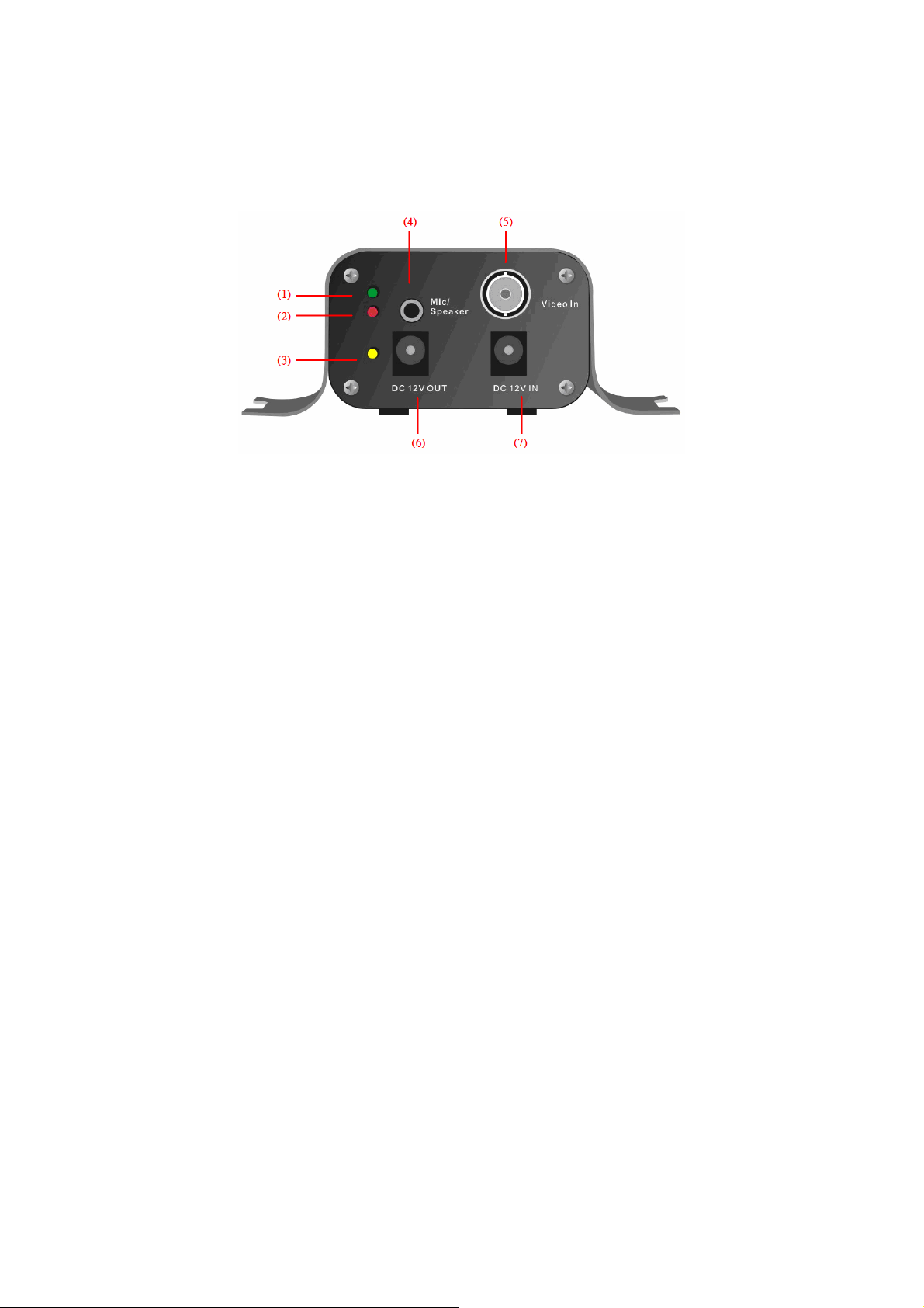
1.3.1 A-side Product View
1. Login indicator: Green light-on indicates user is logging in.
2. System start-up indicator: Blink when system is on.
3. Power: Red light on when power is on.
4. Microphone/Speaker: Use attached audio cord to connect
audio device.
5. Video In: Use 5C2V cable with BNC connector to connect
CCD camera.
6. DC12V OUT: DC 12V power output with maximum 750mA
limited.
7. DC12V IN: Connect attached adapter.
8
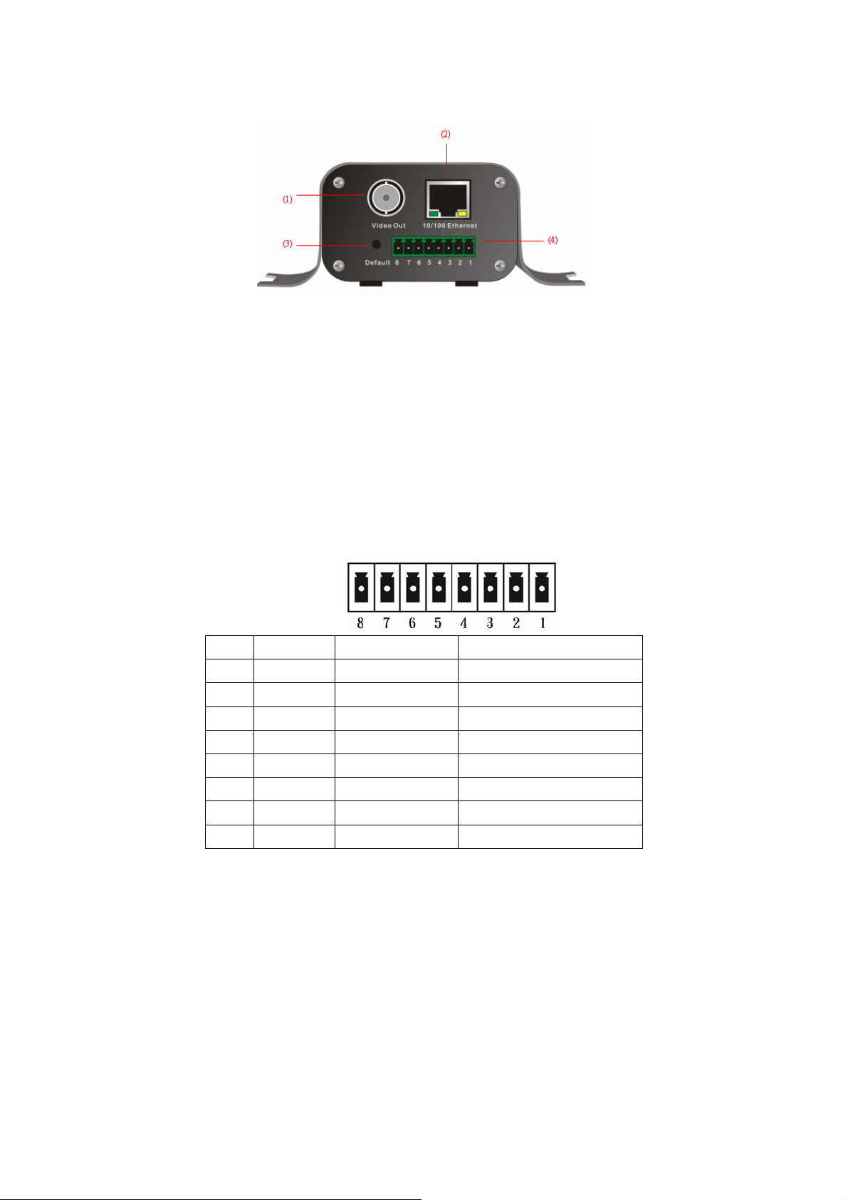
1.3.2 B-side Product View
1. Video Out: BNC output port for better camera images while
installed on-site adjustment only.
2. 10/100 Ethernet: Connect to network by using standard RJ45
connector.
3. Default: Insert this button by using attached L-type wrench or end
of thin paper clip to restore manufacturing default values.
4. I/O & RS-485 Connectors:
Port Function Remark
1 DI1+ DI1 Positive Max. 50mA, 12VDC
2 DI1- DI1 Negative
3 DI2+ DI2 Positive Max. 50mA, 12VDC
4 DI2- DI2 Negative
5 DO+ DO Positive Max. 50mA, 80VDC
6 DO- DO Negative
7 RS485+ TX/RX Non-inverting
8 RS485- TX/RX Inverting
Remark: User can use pan-tilt-zoom images of camera by connecting RS-485.
If distance is too far, please use additional signal amplifier.
9
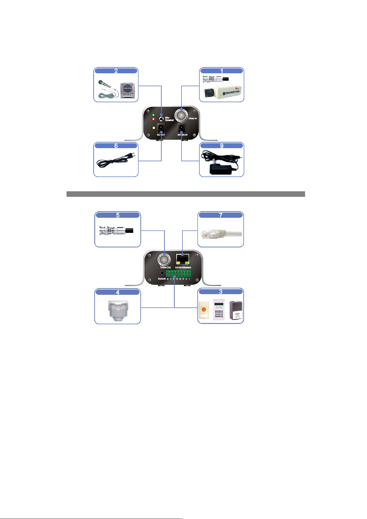
1.4 Installation
z Step 1: Use 5C2V coaxial cable to connect CCD camera.
z Step 2: Connect Microphone/speaker.
z Step 3: Connect security devices into digital inputs/output.
z Step: Connect pan-tilt device into RS-485.
z Step 5: Use 5C2V coaxial cable to connect TV/monitor.
z Step 6: Connect camera DC-12V power into product with
maximum power output 750mA.
z Step 7: Use RJ-45 UTP cable to connect network equipment.
10
z Step 8: Plug-in powers of all optional connected devices.
z Step 9: Plug-in power of video server.
z Step 10: Confirm power indicator is on.
z Step 11: Confirm red-light system is quick blinking.
z Step 12: Start-up PC to start application software installation.
Software Installation
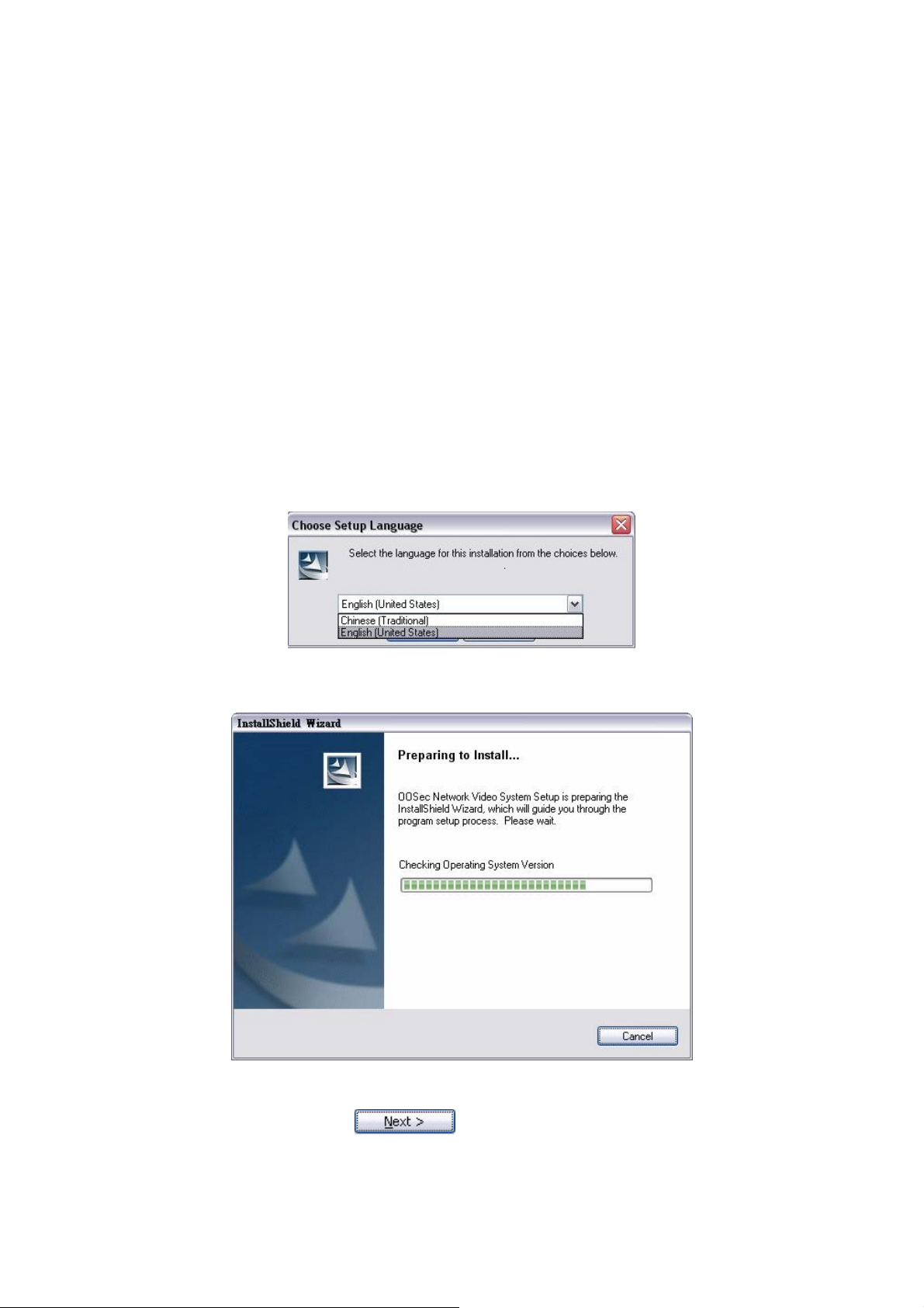
Start CD Software Installation
Before Installation: Insert the CD attached in the package to CD-ROM
reader on your computer, system will start its auto-execution procedure.
Language: System supports two language selection.
System is detecting OS of user’s PC, please wait.
Welcome Page: Click to enter next setup procedure.
11
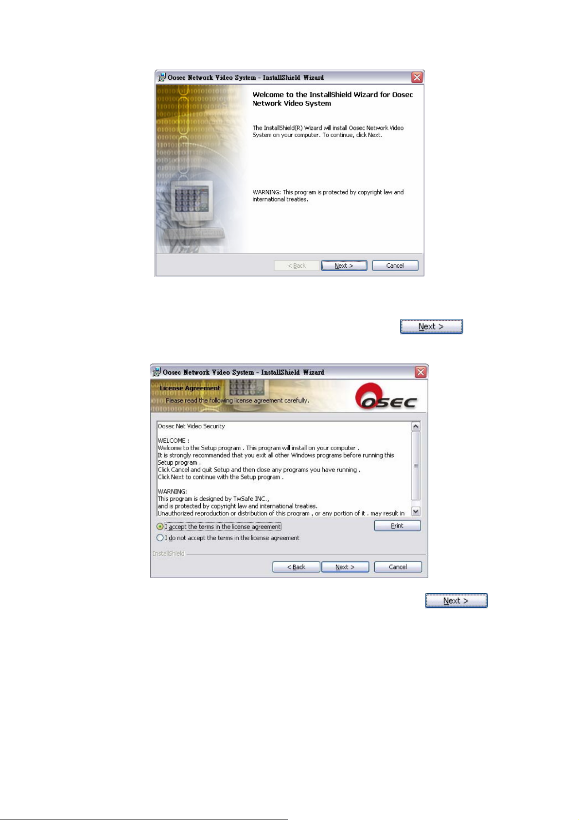
Read Me & Intellectual Property Announcement: User needs to click “I
accept the terms in the license agreement” to enter next step of setup
procedure or the setup sequence will not proceed. Click to
proceed.
Save-path: User defines save path of the execution file. Click
to proceed.
12
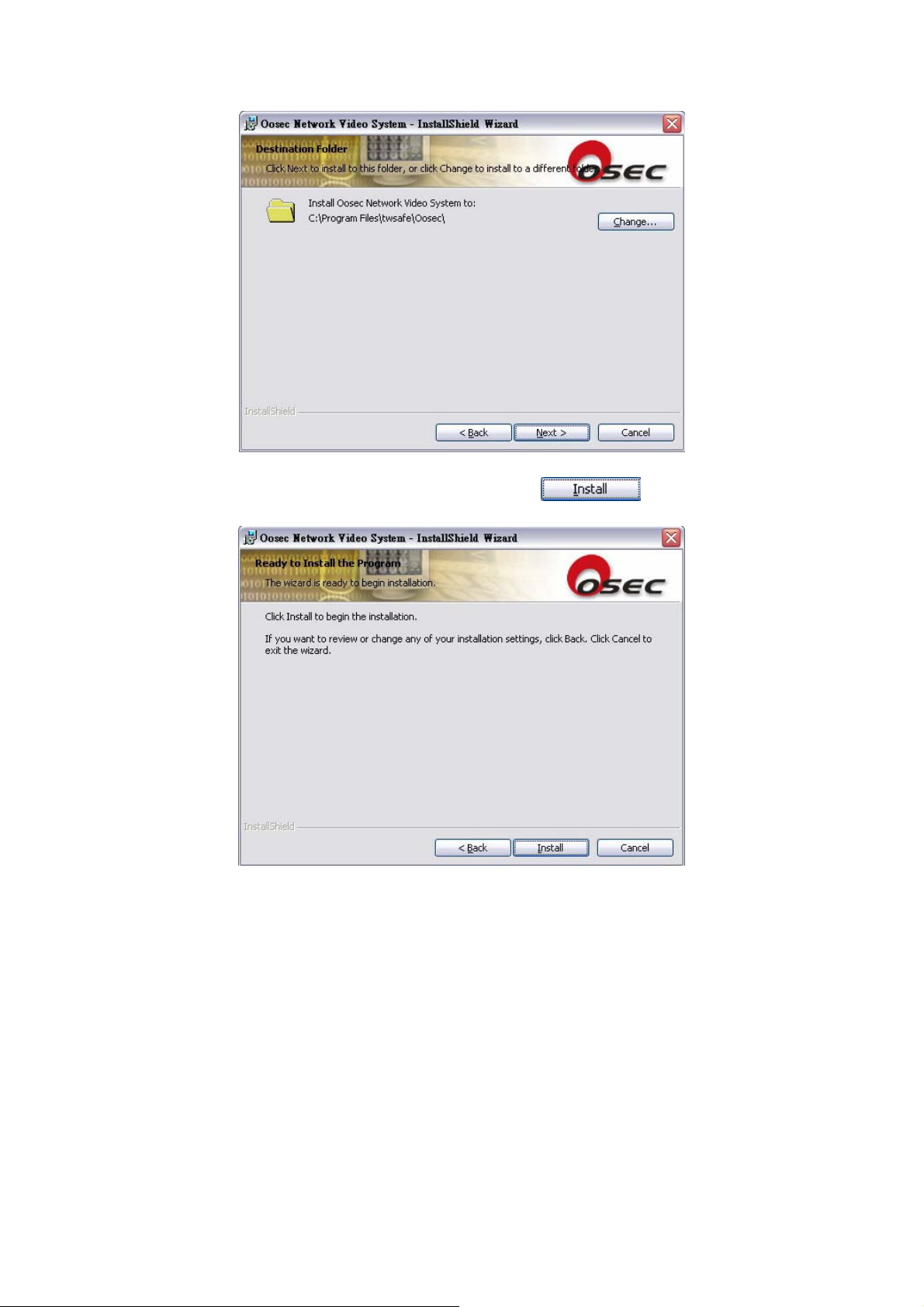
Check: See details of setup are correct. Click to proceed.
Installing: System is installing on your PC, please wait.
13
 Loading...