

OOOZNEST WorkBee CNC Assembly Manual
WORKBEE CNC
Mechanical Assembly Instructions
Screw Driven
WorkBee CNC 1
Contents
1.0 Getting Started ...................................................................................................... 2
1.1 About The Kit ................................................................................................. 2
1.3 Tools Required ................................................................................................ 2
1.4 Notes on Assembly .......................................................................................... 2
2.0 Assembly ............................................................................................................ 4
2.1 Wheel Assembly .............................................................................................. 4
2.2 Y-Plate Assembly ............................................................................................ 5
2.2.2 Y Wheels & Y-Plate-Inner ...................................................................... 6
2.2.3 Stepper Motor ...................................................................................... 8
2.2.4 Repeat ................................................................................................ 9
2.3 X-Carriage Assembly ..................................................................................... 10
2.3.2 Z ACME Nut Block ............................................................................... 12
2.3.3 X ACME Nut Blocks ............................................................................. 13
2.3.4 X Wheels & X-Plate-Front .................................................................... 14
2.3.5 X & Z Mating ...................................................................................... 16
2.3.6 Z Extrusion ........................................................................................ 17
2.3.7 Z Stepper Motor ................................................................................. 18
2.3.8 Z ACME Screw.................................................................................... 19
2.4 X-Gantry Assembly........................................................................................ 21
2.4.2 X-Carriage & Y-Plate-Left Assembly ...................................................... 22
2.4.3 X ACME Screw.................................................................................... 23
2.4.4 Angle Corners .................................................................................... 24
2.5 Base Assembly.............................................................................................. 25
2.5.2 End Plates ......................................................................................... 26
2.5.3 Stepper Motors .................................................................................. 27
2.5.4 Y ACME Screws .................................................................................. 28
2.5.5 End Caps ........................................................................................... 29
2.6 Spoiler Board Support Extrusions - Method 1 .................................................... 30
2.6.2 Y-End-Plate Final Bolts & Angle Corners ................................................ 31
2.6.3 Spoiler Board Support Brackets ............................................................ 32
2.6.4 Attaching Spoiler Board Supports ......................................................... 33
2.7 Spoiler Board Support Extrusions - Method 2 .................................................... 34
2.7.2 Spoiler Board Support Brackets ............................................................ 35
2.7.3 Spoiler Board Support Assembly ........................................................... 36
2.7.4 Attaching Spoiler Board Supports ......................................................... 37
2.8 Complete ...................................................................................................... 38
3.0 Appendix ............................................................................................................ 39
3.1 Appendix A - Kit Contents .............................................................................. 39
WorkBee CNC 2
1.0 Getting Started
1.1 About The Kit
The WorkBee CNC is an open source design designed and introduced by OOOZNEST and is an offspring
of the OX CNC Machine designed by Mark Carew of Open Builds
. 1.2 Check Product Contents
The first thing you should do when you receive your kit is to check the contents against the list in
Appendix A. If anything is missing or damaged (or you have any other problems), please contact us
and we will aim to resolve the issue as quickly as possible.
1.3 Tools Required
The list below shows the main tools that are required to complete this build:
• Set of Allen Keys
• 8.0mm Spanner
• M5Tap
1.4 Notes on Assembly
We recommend that you read through the whole manual before beginning the build, as this enables
you to get a rough idea of how it all goes together. Before starting each step make sure you have
studied the diagram and fully understand what you are doing. A PDF version of the manual is available
on our website, allowing you to zoom in on the diagrams if needed.
When attaching parts, make sure they are properly squared and aligned, and everything should easily
fit together. If a part is requiring significant force to attach, stop, take it off, re-read the instructions,
and try again. Do not over tighten bolts, as you may strip the threads.
If you forget to insert a Tee-Nut when instructed, there is no need to undo any of the work you have
done. We have included spare M5-Drop-In-Tee-Nuts in the kit for this situation. M5-Drop-In-Tee-Nuts
do not have to be inserted from the end of the extrusion - simply place them in the V-Slot, then screw
in the bolt. This will turn them and engage them into the underside of the V-Slot.
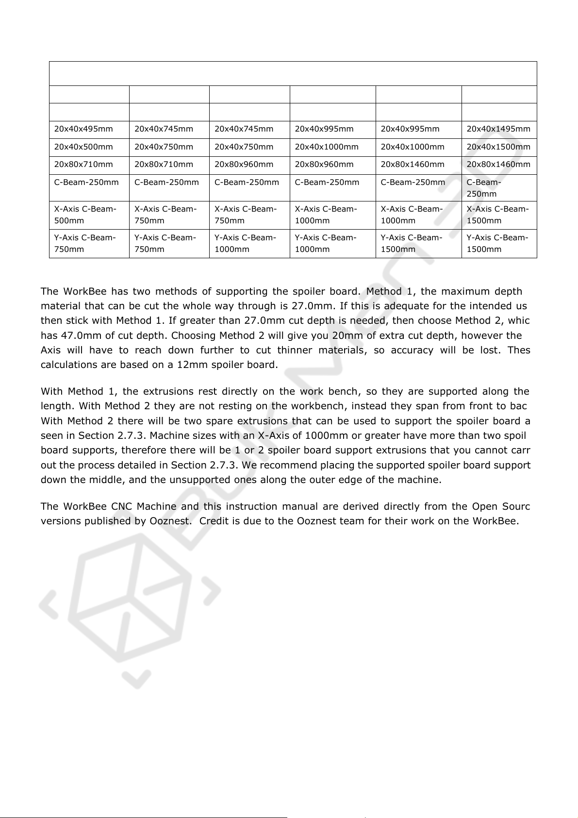
This manual has been written for the construction of a 1500 x 1500 mm screw driven version of the
WorkBee. If you have a different version, everything is the same, except you will be working with
shorter V-Slot extrusions and ACME Lead screws. Use the table below to convert V-Slot dimensions in
this manual to the sizes for your machine.
Check to see if all the V-Slot and C-Beam Extrusion has been tapped, if not then tap to a depth of
around 10mm.
WorkBee CNC 3
Machine Size
500x750mm
750x750mm
750x1000mm
1000x1000mm
1000x1500mm
1500x1500mm
20x40x415mm
20x40x665mm
20x40x665mm
20x40x915mm
20x40x915mm
20x40x1415mm
20x40x495mm
20x40x745mm
20x40x745mm
20x40x995mm
20x40x995mm
20x40x1495mm
20x40x500mm
20x40x750mm
20x40x750mm
20x40x1000mm
20x40x1000mm
20x40x1500mm
20x80x710mm
20x80x710mm
20x80x960mm
20x80x960mm
20x80x1460mm
20x80x1460mm
C-Beam-250mm
C-Beam-250mm
C-Beam-250mm
C-Beam-250mm
C-Beam-250mm
C-Beam-
250mm
X-Axis C-Beam-
500mm
X-Axis C-Beam-
750mm
X-Axis C-Beam-
750mm
X-Axis C-Beam-
1000mm
X-Axis C-Beam-
1000mm
X-Axis C-Beam-
1500mm
Y-Axis C-Beam-
750mm
Y-Axis C-Beam-
750mm
Y-Axis C-Beam-
1000mm
Y-Axis C-Beam-
1000mm
Y-Axis C-Beam-
1500mm
Y-Axis C-Beam-
1500mm
The WorkBee has two methods of supporting the spoiler board. Method 1, the maximum depth of
material that can be cut the whole way through is 27.0mm. If this is adequate for the intended use,
then stick with Method 1. If greater than 27.0mm cut depth is needed, then choose Method 2, which
has 47.0mm of cut depth. Choosing Method 2 will give you 20mm of extra cut depth, however the ZAxis will have to reach down further to cut thinner materials, so accuracy will be lost. These
calculations are based on a 12mm spoiler board.
With Method 1, the extrusions rest directly on the work bench, so they are supported along their
length. With Method 2 they are not resting on the workbench, instead they span from front to back.
With Method 2 there will be two spare extrusions that can be used to support the spoiler board as
seen in Section 2.7.3. Machine sizes with an X-Axis of 1000mm or greater have more than two spoiler
board supports, therefore there will be 1 or 2 spoiler board support extrusions that you cannot carry
out the process detailed in Section 2.7.3. We recommend placing the supported spoiler board supports
down the middle, and the unsupported ones along the outer edge of the machine.
The WorkBee CNC Machine and this instruction manual are derived directly from the Open Source
versions published by Ooznest. Credit is due to the Ooznest team for their work on the WorkBee.
WorkBee CNC 4
2.0 Assembly
2.1 Wheel Assembly
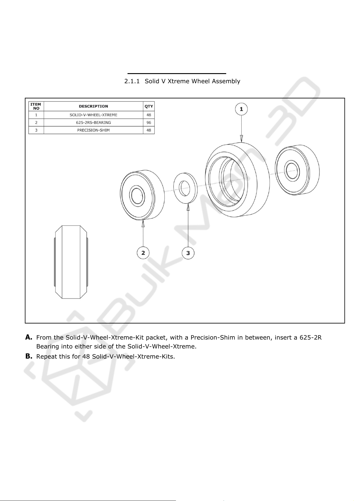
A. From the Solid-V-Wheel-Xtreme-Kit packet, with a Precision-Shim in between, insert a 625-2RS-
Bearing into either side of the Solid-V-Wheel-Xtreme.
B. Repeat this for 48 Solid-V-Wheel-Xtreme-Kits.
WorkBee CNC 5
2.2 Y-Plate Assembly
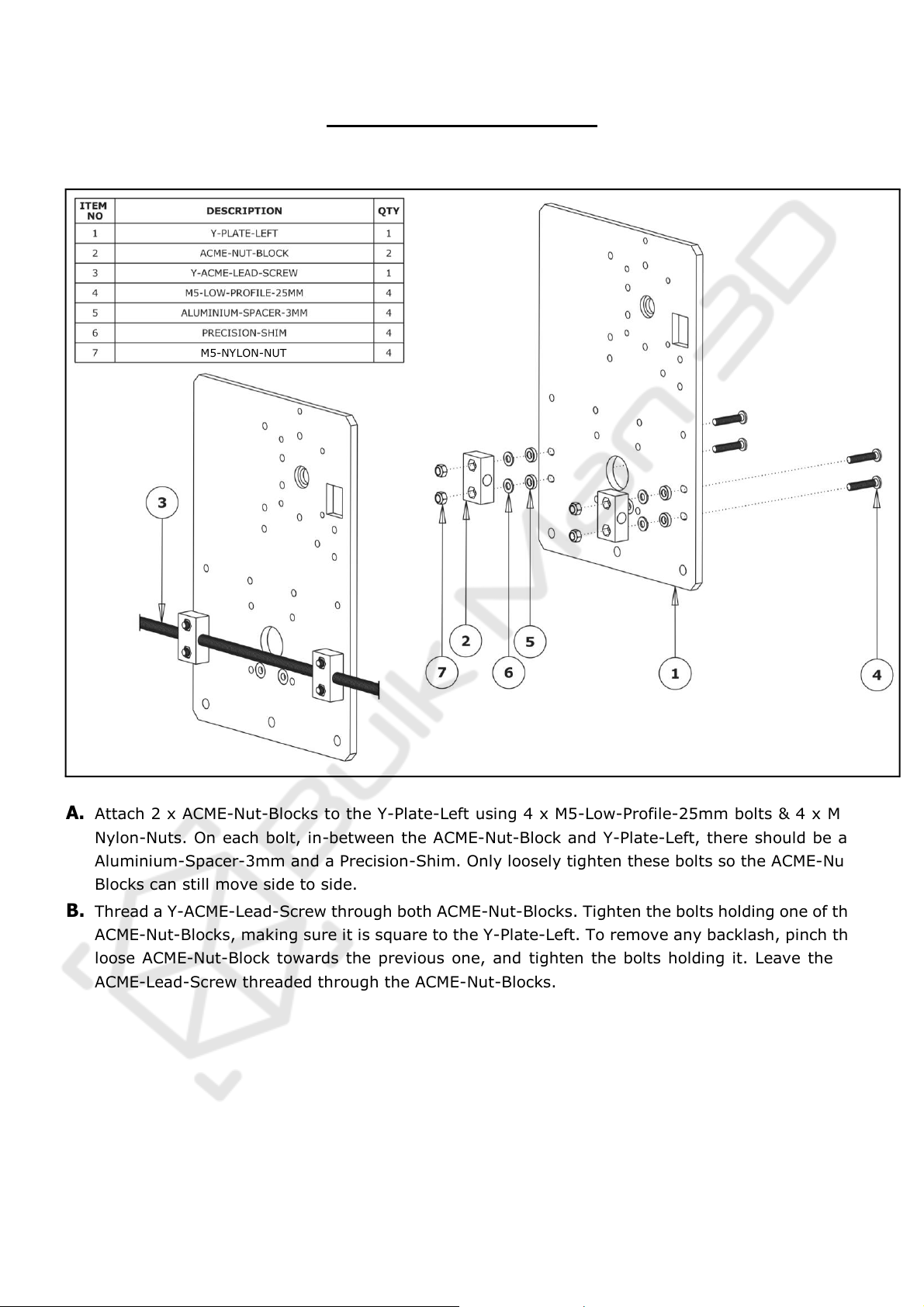
A. Attach 2 x ACME-Nut-Blocks to the Y-Plate-Left using 4 x M5-Low-Profile-25mm bolts & 4 x M5-
Nylon-Nuts. On each bolt, in-between the ACME-Nut-Block and Y-Plate-Left, there should be an
Aluminium-Spacer-3mm and a Precision-Shim. Only loosely tighten these bolts so the ACME-Nut-
Blocks can still move side to side.
B. Thread a Y-ACME-Lead-Screw through both ACME-Nut-Blocks. Tighten the bolts holding one of the
ACME-Nut-Blocks, making sure it is square to the Y-Plate-Left. To remove any backlash, pinch the
loose ACME-Nut-Block towards the previous one, and tighten the bolts holding it. Leave the YACME-Lead-Screw threaded through the ACME-Nut-Blocks.
M5-NYLON-NUT
WorkBee CNC 6
2.2.2 Y Wheels & Y-Plate-Inner
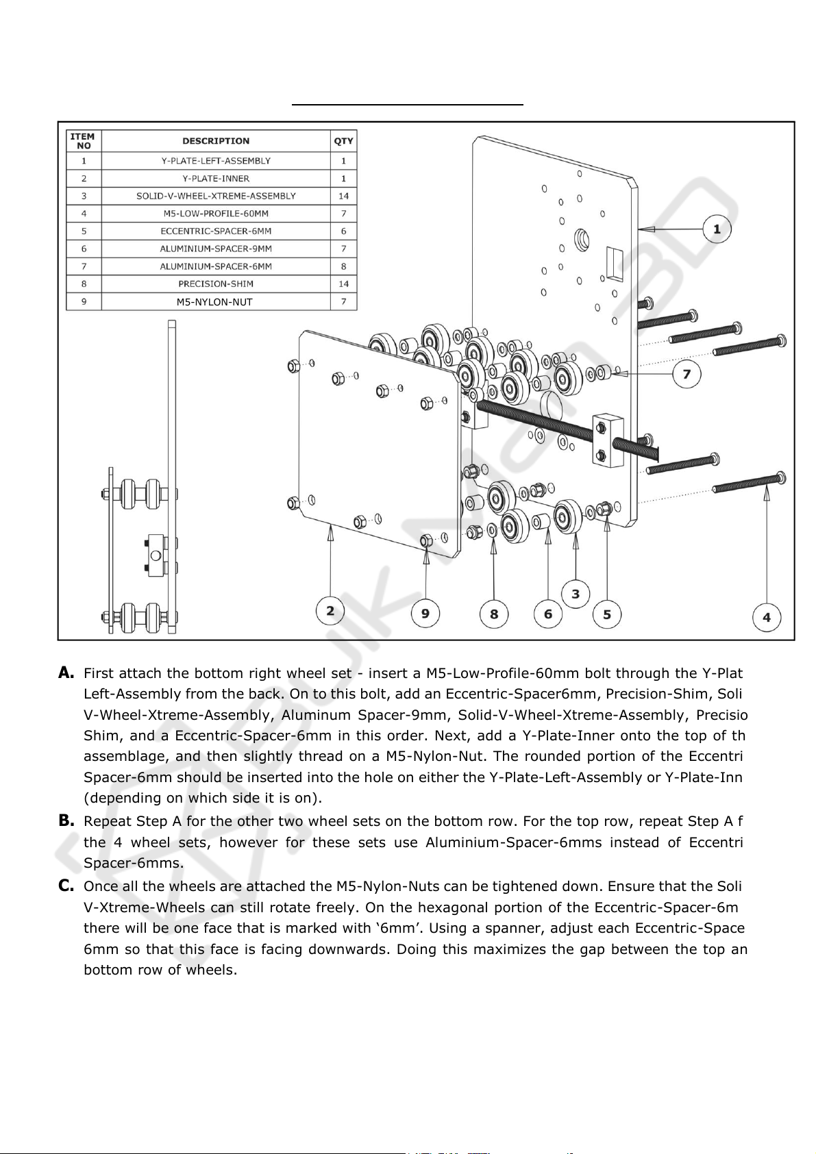
A. First attach the bottom right wheel set - insert a M5-Low-Profile-60mm bolt through the Y-Plate-
Left-Assembly from the back. On to this bolt, add an Eccentric-Spacer6mm, Precision-Shim, Solid-
V-Wheel-Xtreme-Assembly, Aluminum Spacer-9mm, Solid-V-Wheel-Xtreme-Assembly, Precision
Shim, and a Eccentric-Spacer-6mm in this order. Next, add a Y-Plate-Inner onto the top of this
assemblage, and then slightly thread on a M5-Nylon-Nut. The rounded portion of the EccentricSpacer-6mm should be inserted into the hole on either the Y-Plate-Left-Assembly or Y-Plate-Inner
(depending on which side it is on).
B. Repeat Step A for the other two wheel sets on the bottom row. For the top row, repeat Step A for
the 4 wheel sets, however for these sets use Aluminium-Spacer-6mms instead of Eccentric-
Spacer-6mms.
C. Once all the wheels are attached the M5-Nylon-Nuts can be tightened down. Ensure that the Solid-
V-Xtreme-Wheels can still rotate freely. On the hexagonal portion of the Eccentric-Spacer-6mm,
there will be one face that is marked with ‘6mm’. Using a spanner, adjust each Eccentric-Spacer-
6mm so that this face is facing downwards. Doing this maximizes the gap between the top and
bottom row of wheels.
D. Run any piece of C-Beam extrusion in between the two rows of wheels. Initially, the C-Beam will
wobble between the wheels. Turn the assembly upside down so the C-Beam is sitting on the row
of wheels with the Aluminium-Spacer-6mms. Starting with an outside pair of wheels, adjust both
Eccentric-Spacer-6mms down onto the C-Beam Extrusion until there is a small amount of friction
between both wheels and the C-Beam Extrusion. When adjusting the pair of Eccentric-Spacer-
M5-NYLON-NUT

WorkBee CNC 7
6mms ideally they should be adjusted identically. However, sometimes one will need to be
adjusted slightly more than the other to get both wheels engaged with the C-Beam extrusion.
Repeat this for the other outside pair of wheels, and then again for the middle pair.
E. Slide the C-Beam extrusion back and forth through the wheels. This should require a small amount
of force, and all wheels should spin as it rolls. Also check there is no wobbling of the extrusion.
Once happy, double check the tightness of the M5-NylonNuts.
WorkBee CNC 8
2.2.3 Stepper Motor
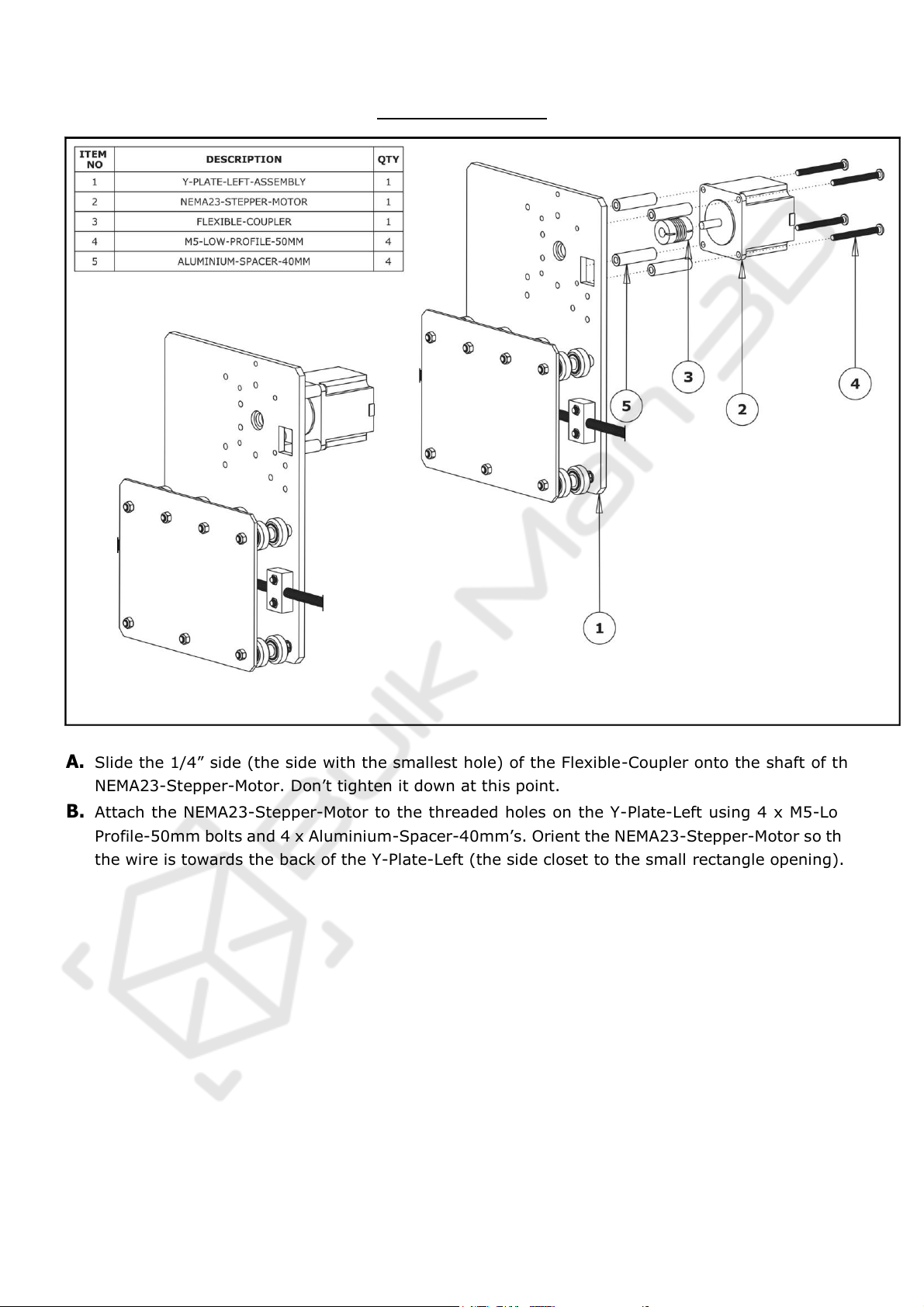
A. Slide the 1/4” side (the side with the smallest hole) of the Flexible-Coupler onto the shaft of the
NEMA23-Stepper-Motor. Don’t tighten it down at this point.
B. Attach the NEMA23-Stepper-Motor to the threaded holes on the Y-Plate-Left using 4 x M5-Low-
Profile-50mm bolts and 4 x Aluminium-Spacer-40mm’s. Orient the NEMA23-Stepper-Motor so that
the wire is towards the back of the Y-Plate-Left (the side closet to the small rectangle opening).
WorkBee CNC 9
2.2.4 Repeat
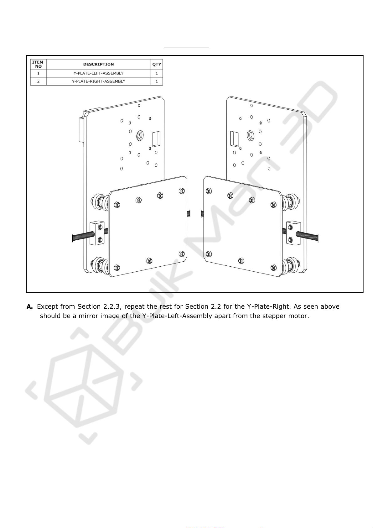
A. Except from Section 2.2.3, repeat the rest for Section 2.2 for the Y-Plate-Right. As seen above it
should be a mirror image of the Y-Plate-Left-Assembly apart from the stepper motor.
WorkBee CNC 10
2.3 X-Carriage Assembly
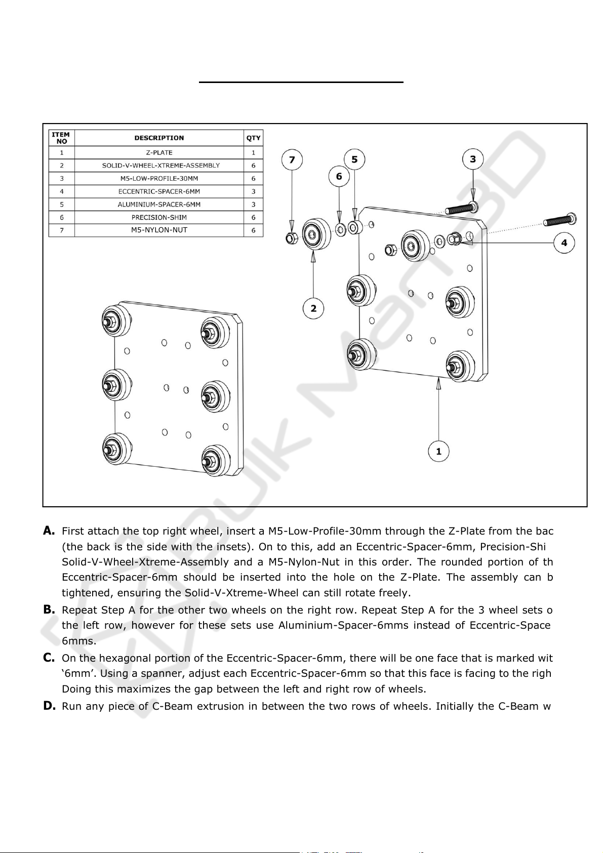
A. First attach the top right wheel, insert a M5-Low-Profile-30mm through the Z-Plate from the back
(the back is the side with the insets). On to this, add an Eccentric-Spacer-6mm, Precision-Shim,
Solid-V-Wheel-Xtreme-Assembly and a M5-Nylon-Nut in this order. The rounded portion of the
Eccentric-Spacer-6mm should be inserted into the hole on the Z-Plate. The assembly can be
tightened, ensuring the Solid-V-Xtreme-Wheel can still rotate freely.
B. Repeat Step A for the other two wheels on the right row. Repeat Step A for the 3 wheel sets on
the left row, however for these sets use Aluminium-Spacer-6mms instead of Eccentric-Spacer-
6mms.
C. On the hexagonal portion of the Eccentric-Spacer-6mm, there will be one face that is marked with
‘6mm’. Using a spanner, adjust each Eccentric-Spacer-6mm so that this face is facing to the right.
Doing this maximizes the gap between the left and right row of wheels.
D. Run any piece of C-Beam extrusion in between the two rows of wheels. Initially the C-Beam will
wobble between the wheels. Turn the assembly so the C-Beam is sitting on the row of wheels with
the Aluminium-Spacer-6mms. Starting with an outside wheel, adjust the Eccentric-Spacer-6mm
down onto the C-Beam Extrusion until there is a small amount of friction between the wheel and
the C-Beam Extrusion. Repeat this for the other outside wheel, and then for the middle wheel.
M5-NYLON-NUT

WorkBee CNC 11
E. Slide the C-Beam extrusion back and forth through the wheels. This should require a small amount
of force, and all wheels should spin as it rolls. Also check there is no wobbling of the extrusion.
Once happy, double check the tightness of the M5-Nylon-Nuts.
 Loading...