

Page 1

Mobile Cart Computer
V E N U S 1 9 1 / 2 2 1
VENUS-221/191
22”/19” LCD with LED Backlight
Intel® N2800 Dual Core Processor
Mobile Cart Computer
User Guide
VENUS-221/VENUS-191 Manual 1st Ed
May, 2014
Page 2

Mobile Cart Computer
V E N U S 1 9 1 / 2 2 1
Copyright Notice
This document is copyrighted, 2013. All rights are reserved. The
original manufacturer reserves the right to make improvements to
the products described in this manual at any time without notice.
No part of this manual may be reproduced, copied, translated, or
transmitted in any form or by any means without the prior written
permission of the original manufacturer. Information provided in
this manual is intended to be accurate and reliable. However, the
original manufacturer assumes no responsibility for its use, nor for
any infringements upon the rights of third parties, which may result
from its use.
The material in this document is for product information only and
is subject to change without notice. While reasonable efforts have
been made in the preparation of this document to assure its
accuracy, ONYX Healthcare Inc., assumes no liabilities resulting
from errors or omissions in this document, or from the use of the
information contained herein
ONYX Healthcare Inc. reserves the right to make changes in the
product design without notice to its users
Page 3

Mobile Cart Computer
V E N U S 1 9 1 / 2 2 1
Packing List
Before you begin installing your Mobile Cart Computer, please make
sure that the following items have been shipped:
VENUS191/221 Mobile Cart Computer
Medical power adaptor 150W/24V
Lithium batteries x2
If any of these items are missing or damaged, you should contact
your distributor or sales representative immediately.
Headquarters
Onyx Healthcare Inc.
2F, No.135, Lane 235, Pao-Chiao Rd.,
Hsin-Tien City, Taipei 231, Taiwan, R.O.C.
TEL: +886-2-8919-2188
FAX: +886-2-8919-1699
E-mail: sales@onyx-healthcare.com
http://www.onyx-healthcare.com
Worldwide Offices:
Onyx Healthcare, USA Inc.
324 W. Blueridge Ave.,
Page 4

Mobile Cart Computer
V E N U S 1 9 1 / 2 2 1
Orange, CA 92865, USA
Tel : +1-714-792-0774
Fax: +1-714-792-0481
Email: usasales@onyx-healthcare.com
usa.onyx-healthcare.com
Onyx Healthcare EUROPE B.V.
Ekkersrijt 4002, 5692 DA Son, The Netherlands
Tel : +31-(0)499-462020
Fax: +31-(0)499-462010
Email: eusales@onyx-healthcare.com
e-FAE@onyx-healthcare.com (RMA)
Onyx Healthcare Technology GmbH
An der Trift65d
63303 Dreieich , Germany
TEL: +49-(0)61033-7479-00
Fax: +49-(0)61033-7479-49
Email: eusales@onyx-healthcare.com
e-FAE@onyx-healthcare.com (RMA)
Onyx Healthcare (SU ZHOU) INC.
Room 12, 2F, Building B, No.5 Xing Han Street, Suzhou Industrial
Page 5

Mobile Cart Computer
V E N U S 1 9 1 / 2 2 1
Park, Jiang Su Province, China
Tel: +86-512-67625700
Fax: +86-512-67617337
Email: cnsales@onyx-healthcare.com
Page 6

Mobile Cart Computer
V E N U S 1 9 1 / 2 2 1
Safety & Warranty
1. Read these safety instructions carefully.
2. Keep this user's manual for later reference.
3. Disconnect this equipment from any AC outlet before cleaning.
Do not use liquid or spray detergents for cleaning. Use a damp
cloth.
4. For pluggable equipment, the power outlet must be installed
near the equipment and must be easily accessible.
5. Keep this equipment away from humidity.
6. Put this equipment on a reliable surface during installation.
Dropping it or letting it fall could cause damage.
7. The openings on the enclosure are for air convection. Protect
the equipment from overheating. DO NOT COVER THE
OPENINGS.
8. Make sure the voltage of the power source is correct before
connecting the equipment to the power outlet.
9. WARNING: To avoid risk of electric shock, this equipment
must only be connected to a supply mains with protective
earth. (AVERTISSEMENT: Pour éviter tout risque de choc
électrique, cet appareil doit être connecté à une
alimentation secteur avec une prise de terre)
10. Position the power cord so that people cannot step on it. Do
not place anything over the power cord.
11. All cautions and warnings on the equipment should be noted.
Page 7

Mobile Cart Computer
V E N U S 1 9 1 / 22 1
12. If the equipment is not used for a long time, disconnect it from
the power source to avoid damage by transient over-voltage.
13. Never pour any liquid into an opening. This could cause fire or
electrical shock.
14. Never open the equipment. For safety reasons, only
qualified service personnel should open the equipment.
15. Warning: Do not modify this equipment without
authorization of the manufacturer. (Avertissement: Ne pas
modifier cet équipement sans l'autorisation du fabricant)
16. If any of the following situations arises, get the equipment
checked by service personnel:
a. The power cord or plug is damaged.
b. Liquid has penetrated into the equipment.
c. The equipment has been exposed to moisture.
d. The equipment does not work well, or you cannot get it
to work according to the users manual.
e. The equipment has been dropped and damaged.
f. The equipment has obvious signs of breakage.
17. DO NOT LEAVE THIS EQUIPMENT IN AN UNCONTROLLED
ENVIRONMENT WHERE THE STORAGE TEMPERATURE IS
BELOW -20° C (-4°F) OR ABOVE 60° C (140° F). IT MAY
DAMAGE THE EQUIPMENT.
18. External equipment intended for connection to signal
input/output or other connectors, shall comply with
relevant UL / IEC standard (e.g. UL 1950 for IT equipment
and ANSI/AAMI ES 60601-1: 2005 AND CAN/CSA-C22.2 No.
60601-1:08 / IEC 60601 series for systems – shall comply
Page 8

Mobile Cart Computer
V E N U S 1 9 1 / 22 1
with the standard IEC 60601-1-1, Safety requirements for
medical electrical systems. Equipment not complying
with UL 60601-1 shall be kept outside the patient
environment, as defined in the standard.
Caution:
It may cause the danger of explosion if battery is incorrectly
replaced. Replace only with same or equivalent type
recommended by the manufacturer.
Page 9

Mobile Cart Computer
V E N U S 1 9 1 / 22 1
Classification
1. Degree of production against electric shock: not classified
2. Degree of protection against the ingress of water: Front IP65 and
body IPX1
3. Mode of operation: Continuous
4. Type of protection against electric shock: Class I equipment
5. No Applied Part, No AP/APG
Page 10

Mobile Cart Computer
V E N U S 1 9 1 / 22 1
FCC
This device complies with Part 18 FCC
Rules. Operation is subject to the following
two conditions: (1) this device may not
cause harmful interference, and (2) this
device must accept any interference
received including interference that may
cause undesired operation.
Page 11
Mobile Cart Computer
V E N U S 1 9 1 / 22 1
UL Module Description
VENUS-191 / 221 modules are developed to
suitable for the Classification Mark
requirement
Page 12
Mobile Cart Computer
V E N U S 1 9 1 / 22 1
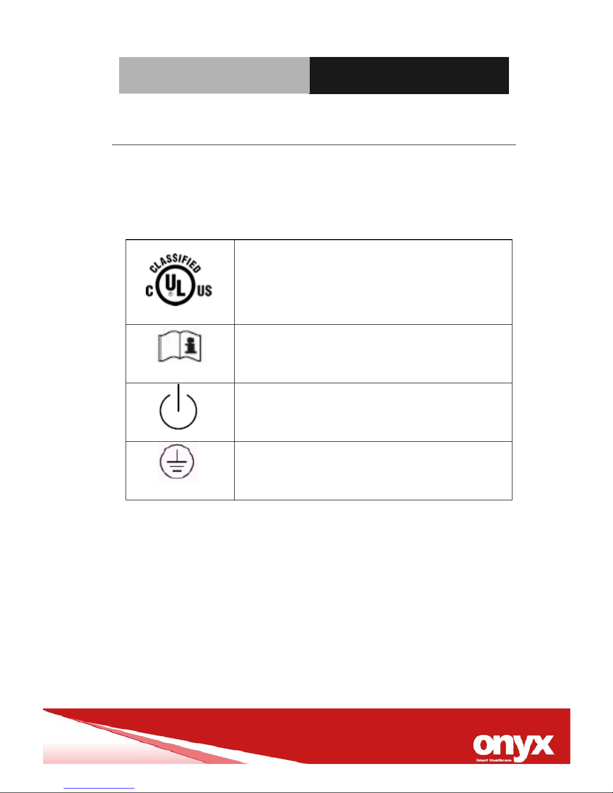
Safety Symbol Description
The following safety symbols are the further explanations for your
reference.
Medical equipment with respect to electric
shock, fire and mechanical hazards only in
accordance with ANSI/AAMI ES 60601-1:
2005 AND CAN/CSA-C22.2 No.
60601-1:08
Attention, consult ACCOMPANYING
DOCUMENTS.
Stand-by
Ground wire
Protective Ground wire.
Page 13

Mobile Cart Computer
V E N U S 1 9 1 / 22 1
Contents
Chapter 1 General Information
1.1 Introduction ..................................................................... 14
1.2 Feature ............................................................................. 15
1.3 Specification .................................................................... 16
1.4 Dimension ........................................................................ 20
Chapter 2 Hardware Installation
2.1 Safety Precautions ..............................................................
2.2 Quick Tour of the VENUS-191 ............................................
2.3 Turn On and Boot up into Windows………………………..
2.4 Turn off…………………………………………………………..
Chapter 3 Driver Installation
3.1 Driver installation……………………………………………….
3.2 SBMS introduction……………………………………………...
Appendix A Miscellanea
A.1 General Cleaning Tips ........................................................
A.2 Cleaning Tools ....................................................................
A.3 Scrap Computer Recycling ..............................................
Page 14

Mobile Cart Computer
V E N U S 1 9 1 / 22 1
General
Information
Chapter
1
Page 15

Mobile Cart Computer
V E N U S 1 9 1 / 2 2 1
Chapter 2 Hardware Installation 2-1
1.1 Introduction
The VENUS-191/221 Mobile cart computer are based on Intel®
AtomTM N2800 Dual Core processor, It accommodates one 2.5”
SATAII SSD and 4GB DDRIII SODIMM.
The VENUS series both offer 4:3 (19inch) and 16:9 (22 inch) wide
range size with high brightness backlight LCD display with high
resolutions.
Fan-less and no vent design, both unique features of VENUS-191/
VENUS-221 reduces the risk of cross-infection dramatically and
also makes daily cleaning quickly and safe. Front IP65 and body
IPX1 design provide the most reliable proof against water leakage.
Germs have no corners to hide in while cleaning because of smooth
and seamless surface design.
VENUS-191/221 owns side mount two USB 3.0 ports, and a smart
card reader to support high speed data transfer and ID check by
smart card reader.
Dual hot swappable lithium-ion battery innovation design provides
stable 125W power to system for standing 6 hours of running,
non-stop 24/7 support service in hospital. The VENUS-191/221 is
definitely your perfect choices.
Page 16

Mobile Cart Computer
V E N U S 1 9 1 / 2 2 1
Chapter 2 Hardware Installation 2-2
1.2 Feature
Intel
®
N2800 1.86GHz Dual Core Processor
19” 1280 x1024 / 22” 1366 x 768 LCD with LED backlight.
Dual hot swappable lithium batteries, support non-stop
operation.
Fully cable-less, easy deployment
Smart Battery management system.
Ergonomic illumination reading light bar
Both of LED indicators reminding the state of charge
Fully Cable-less mobile design, easy deployment
5 Smart Function Keys
4KV Medical isolated USB/COM/LAN ports
High Speed USB 3.0 Ports
Water-proof :IP65 Front panel, Rear IPX1
Light weight design with Magnesium / Aluminum alloy rear
cover
Low power solution with fan-less design make VENUS more
reliable..
Total certification solution for medical devices of EN60601-1
standard.
Page 17

Mobile Cart Computer
V E N U S 1 9 1 / 2 2 1
Chapter 2 Hardware Installation 2-3
1.3 Specification
Hardware Specifications
Display
VENUS-221: 21.5” 1366x768 LCD
VENUS-191: 19” 1280x1024 LCD
CPU
Intel® N2800 1.86GHz
Disk Drive
2.5” SATA Solid State Drive
Function
Key
Power On/Off, LCD Brightness Up/Down, Touch Screen
On/Off, Reading Light On/Off
Security
Smart Card reader, RFID
I/O
2x Isolated RS-232 port
1x Isolated USB 2.0 port
4x USB 2.0 ports
4x USB 3.0 ports
2x Isolated Gigabit LAN
1x Display Port
Sound:
1 x Line-out
1 x Mic-in
LCD Specifications
Model Name
VENUS-221 series
VENUS-191
Display Type
21.5” LCD
19” LCD
Max. Resolution
1366 x 768
1280 x 1024
Max. Colors
16.7M
16.7M
Dot Size (mm)
0.294 x 0.294
0.297 x 0.297
Luminance (cd/m2)
250(TYP)
250 (TYP)
Back Light Life Time
30,000 Hrs
30,000 Hrs
Page 18

Mobile Cart Computer
V E N U S 1 9 1 / 2 2 1
Chapter 2 Hardware Installation 2-4
Touch Screen Specification
Type
5-wire Resistive
Interface
USB interface
Light Transmission
> 75%
Life Time
35 million activations
Power Supply Specifications
Model
Hitron HEMP152G-S240060-7(J)
Input Voltage
100-240V AC( 50/60 Hz)
Output Voltage
24V, 6.25A, 150W max.
Battery Specifications
Manufacturer/model
Gallopwire/OPM-P01T-00
Battery Capacity
62.6Wh
Output Voltage
10.8V
Sustaining Time
6 hours
Environmental Specifications
Operating Temperature
10˚C to 40˚C (32˚F ~86˚F)
Storage Temperature
-20˚C to 60˚C (-4˚F ~140˚F)
Storage Humidity
10% to 90%@ 40˚C, non-condensing
Vibration
0.5G / 5 ~ 500Hz (Random) / operation
Page 19

Mobile Cart Computer
V E N U S 1 9 1 / 2 2 1
Chapter 2 Hardware Installation 2-5
Shock
15G peak acceleration (11 msec. duration) /
operation
Drop
76cm (1 Corner, 3 Edge, 6 Surface)
EMI / Safety
CE / FCC Class B/ANSI AAMI ES60601-1/
EN 60601-1
Note:
All ONYX LCD products are manufactured with High precision technology.
However, there are a small number of defective pixels in all LCD panels
that are not able to change color. This is a normal occurrence for all LCD
displays from all manufacturers and should not be noticeable or
objectionable under normal operation. All LCD panels are qualified for
industry standard conditions in the following: total 7 dead pixels on a
screen or if there are 3 within 1 inch square area of each other on the
display.
Page 20

Mobile Cart Computer
V E N U S 1 9 1 / 2 2 1
Chapter 2 Hardware Installation 2-6
1.4 Dimension
VENUS-191
Page 21

Mobile Cart Computer
V E N U S 1 9 1 / 2 2 1
Chapter 2 Hardware Installation 2-7
VENUS-221
Page 22

Mobile Cart Computer
V E N U S 1 9 1 / 2 2 1
Chapter 2 Hardware Installation 2-8
Hardware
Installation
Chapter
2
Page 23

Mobile Cart Computer
V E N U S -1 9 1 / 2 2 1
Chapter3 Award BIOS Setup 3-1
2.1 Safety Precautions
Always completely disconnect the power cord
from your board whenever you are working on
it. Do not make connections while the power is
on, because a sudden rush of power can
damage sensitive electronic components.
Always ground yourself to remove any static
charge before touching the board. Modern
electronic devices are very sensitive to static
electric charges. Use a grounding wrist strap at
all times. Place all electronic components on a
static-dissipative surface or in a static-shielded
bag when they are not in the chassis
Page 24

Mobile Cart Computer
V E N U S -1 9 1 / 2 2 1
Chapter3 Award BIOS Setup 3-2
2.2 Quick Tour of the VENUS-191 / 221
Before you start to set up the VENUS-191 / 221 take a moment to
become familiar with the locations and purposes of the controls,
drives, connections and ports, which are illustrated in the figures
below.
When you place the VENUS-191 /221 upright on the desktop, its
front panel appears as shown in Picture 2-2-1 and 2-2-2.
Picture 2-2-1: Front View of the VENUS-191
Page 25

Mobile Cart Computer
V E N U S -1 9 1 / 2 2 1
Chapter3 Award BIOS Setup 3-3
Picture 2-2-2: Front View of the VENUS-221
Page 26

Mobile Cart Computer
V E N U S -1 9 1 / 2 2 1
Chapter3 Award BIOS Setup 3-4
5 Smart Program Keys
ICON
VENUS-191/ VENUS-221
One touch for reading light on/off
One touch for screen on/off
One touch for LCD brightness down
Continue press fall down to minimum
One touch for LCD brightness up
Continue press rising up to maximum
One touch for system enter sleeping mode,
Long press 4 seconds to shut-down the
system.
Page 27

Mobile Cart Computer
V E N U S -1 9 1 / 2 2 1
Chapter3 Award BIOS Setup 3-5
When you turn the Mobile Cart Computer around and look at its
rear cover, the sunken I/O section is at the bottom of the station, as
shown in Picture 2-2-3 . (The I/O section includes various I/O ports,
including a serial port, Display Port, the Ethernet ports, USB ports,
the microphone jack, and so on.) The Cart Mobile Computer
integrates WLAN function by using Mini Card.
Picture 2-2-3: back view of the VENUS-191 /221
VENUS-191 / 221
Page 28

Mobile Cart Computer
V E N U S -1 9 1 / 2 2 1
Chapter3 Award BIOS Setup 3-6
When you turn the Mobile Cart Computer around and look at its
right/left side, two USB 3.0 ports, the smart card reader and Lithium
Battery are as shown in Picture 2-2-4.
Picture 2-2-4: Side view of the VENUS-191/221
Page 29

Mobile Cart Computer
V E N U S -1 9 1 / 2 2 1
Chapter3 Award BIOS Setup 3-7
2.3 Turn On and Boot up into Windows OS
This section is for Windows operating system only. If you are
installing a different operating system, please contact your vendor
for installation details.
Before you start to install OS, you need to check the built-in battery
level light to make sure the light is not purple color.
Your VENUS will begin loading Windows OS once you push the
power button to turn power on. After less than one minute, Windows
desktop screen will appear.
You can select the programs from the start menu in the left-down
corner of the desktop screen.
2.4 Turn off
Turning off VENUS properly is important for system reliability. There
are two ways to turn off the system.
1. On the start menu, click “Shut down” and select “OK”
2. Push the power button and then the system will shut down
automatically
Page 30

Mobile Cart Computer
V E N U S -1 9 1 / 2 2 1
Chapter3 Driver Installation 3-1
Driver
Installation
Chapter
3
Page 31

Mobile Cart Computer
V E N U S -1 9 1 / 2 2 1
Appendix A Miscellanea A-1
3.1 Driver installation
There are several installation ways depending on the driver
package under different Operating Systems.
Please follow the sequence below to install the drivers:
Step 1 – Install Chipset Driver
Step 2 – Install VGA Driver
Step 3 – Install LAN Driver
Step 4 – Install Audio Driver
Step 5 – USB 3.0 Driver
Step 6 – WIFI Driver (Optional)
Step 7 – RFID Driver(Optional)
Step 8 – Touch Panel Driver
Step 9 – Light Sensor
Page 32

Mobile Cart Computer
V E N U S -1 9 1 / 2 2 1
Appendix A Miscellanea A-2
3.2 VENUS Smart Battery Management System
introduction (patent pending)
In this section you will find the step of setup and installation and
recommendations for sBMS. Carefully read all instructions prior to
setting up your sBMS.
Copyright and Trademark Notices
This document contains information that is protected by copyright.
All rights are reserved. No part of this document may be
photocopied, reproduced or translated to another language
without prior written consent of ONYX Healthcare Company.
Other important information
ONYX-Healthcare Company reserves the right to change or amend
this user guide at any time without notice.
Page 33

Mobile Cart Computer
V E N U S -1 9 1 / 2 2 1
Appendix A Miscellanea A-3
Installing the sBMS control software
Run the Setup exe. Application in the installer folder on your
Setup CD or driver also can be found on our website
http://www.onyx-healthcare.com/ServicesSupport.php
Click “Next” at the Welcome to the Onyx-Healthcare SBMS setup
wizard.
Page 34

Mobile Cart Computer
V E N U S -1 9 1 / 2 2 1
Appendix A Miscellanea A-4
Choose the destination folder where the application will be installed.
Select start menu folder and click the “Next”
Page 35

Mobile Cart Computer
V E N U S -1 9 1 / 2 2 1
Appendix A Miscellanea A-5
Page 36

Mobile Cart Computer
V E N U S -1 9 1 / 2 2 1
Appendix A Miscellanea A-6
Select additional tasks if you would like to create an icon on the
screen.
Page 37

Mobile Cart Computer
V E N U S -1 9 1 / 2 2 1
Appendix A Miscellanea A-7
Click “Install” for running installation process.
Page 38

Mobile Cart Computer
V E N U S -1 9 1 / 2 2 1
Appendix A Miscellanea A-8
You have now successfully installed the software. Click the “Finich”
button to exit the installation.
You can run Onyx-Healthcare sBMS control software now.
Page 39

Mobile Cart Computer
V E N U S -1 9 1 / 2 2 1
Appendix A Miscellanea A-9
Explanation of symbols
Symbol
Function
Feature
Battery
Capacity
-Battery bar displaying
3 colors of green,
yellow and purple.
-Independent design
manages each battery
capacity separately.
Remind alarm
setting
-Two primary levels
protection of reminder
alarm, pop-up on the
screen or voice alarm
sounds to warming end
user the battery getting
lower capacity need to
change another
fully-charged battery
soon.
Tool list
-Multi-language
options.
-Default setting
Battery
information
IT manager can gets the
detailed management
information about both
of batteries
manufacturing date,
life cycle, consumption
and temperature…etc.
Page 40

Mobile Cart Computer
V E N U S -1 9 1 / 2 2 1
Appendix A Miscellanea A-10
Service
information
ONYX contact
information
Page 41

Mobile Cart Computer
V E N U S -1 9 1 / 2 2 1
Appendix A Miscellanea A-11
SBMS control panel
Power status:
AC mode means switch the powered from power adaptor,
DC mode means switch the powered from lithium batteries.
Battery bar : Average capacity of two batteries.
-Green: average capacity at 40% or more.
-Yellow: average capacity between 21~39%
-Purple: average capacity less than 20%
Battery LED indicator (L): Single battery capacity on left side.
Battery LED indicator(R): Single battery capacity at right side.
Page 42

Mobile Cart Computer
V E N U S -1 9 1 / 2 2 1
Appendix A Miscellanea A-12
Remind Alarm
Two primary levels protection of remaining alarm
SBMS provide you flexibility of setting alarm, you can set reminder
in two ways to replace the batteries as below table.
Level
Low capacity
Running out of
battery
Set-up range
15~30%
7~30%
Warning alarm
Choose you
preferred one
alternative option
for lower capacity
remaining.
Both of continue 2
short beeps sound
and pop-up screen
while the battery
average capacity
lower than the
setting limit.
Page 43

Mobile Cart Computer
V E N U S -1 9 1 / 2 2 1
Appendix A Miscellanea A-13
Tool List
This page can show you how to set up and use multiple language
input options on your computer.
1. Enter your user name and password to select your favorite
language.
2. Save your changes and completed.
Page 44

Mobile Cart Computer
V E N U S -1 9 1 / 2 2 1
Appendix A Miscellanea A-14
Information:
Design capacity: Basically the amount of charge.
Relative status of charge: The direct way to measure the status of
charge (SOC) of a lithium-ion battery gives the relative value of its
charge.
Cycle count: Once the battery deliver 100% capacity discharge
rate equal to 1 cycle count.
Battery temperature: Show the actually battery operating
temperature. The range of battery recharge is between 0~45℃, and
discharge is between 0~60℃。
Battery current: Show the battery operating range,
Recharge between :0 ~ +2900mA, Discharge between 0 ~ 4000mA
Battery voltage: Normally the battery voltage operating range
between 10800mV to 12600mV.
Serials number: Show the digitals of battery serial number.
Page 45

Mobile Cart Computer
V E N U S -1 9 1 / 2 2 1
Appendix A Miscellanea A-15
Miscellanea
Appendix
A
Page 46

Mobile Cart Computer
V E N U S -1 9 1 / 2 2 1
Appendix A Miscellanea A-16
A.1 General Cleaning Tips
You may need the following precautions before you begin to clean
the computer. When you clean any single part or component for the
computer, please read and understand the details below fully.
1. Never spray or squirt the liquids directly onto any computer
component. If you need to clean the device, please rub it
with a piece of dry cloth.
2. Be cautious of the tiny removable components when you
use a vacuum cleaner to absorb the dirt on the floor.
3. Turn the system off before you start to clean up the
component or computer.
4. Never drop the components inside the computer or get
circuit board damp or wet.
5. Be cautious of all kinds of cleaning solvents or chemicals
when you use it for the sake of cleaning. Some individuals
may be allergic to the ingredients.
6. Try not to put any food, drink or cigarette around the
computer.
Page 47

Mobile Cart Computer
V E N U S -1 9 1 / 2 2 1
Appendix A Miscellanea A-17
A.2 Cleaning tools
Although many companies have created products to help improve
the process of cleaning your computer and peripherals users can
also use household items to clean their computers and peripherals.
Below is a listing of items you may need or want to use while
cleaning your computer or computer peripherals.
Keep in mind that some components in your computer may only be
able to be cleaned using a product designed for cleaning that
component, if this is the case it will be mentioned in the cleaning
tips.
Cloth - A piece of cloth is the best tool to use when rubbing
up a component. Although paper towels or tissues can be
used on most hardware as well, we still recommend you to
rub it with a piece of cloth.
Water or rubbing alcohol – You may moisten a piece of
cloth a bit with some water or rubbing alcohol and rub it on
the computer. Unknown solvents may be harmful to the
plastics parts.
Vacuum cleaner - Absorb the dust, dirt, hair, cigarette
particles, and other particles out of a computer can be one
of the best methods of cleaning a computer. Over time
these items can restrict the airflow in a computer and cause
circuitry to corrode.
Page 48

Mobile Cart Computer
V E N U S -1 9 1 / 2 2 1
Appendix A Miscellanea A-18
Cotton swabs - Cotton swaps moistened with rubbing
alcohol or water are excellent tools for wiping hard to reach
areas in your keyboard, mouse, and other locations.
Foam swabs - Whenever possible it is better to use lint
free swabs such as foam swabs.
Please follow the steps below.
1. Close all application programs.
2. Close operating software.
3. Turn off power switch
4. Remove all device
5. Pull out power cable
Note:
We strongly recommended that you should shut down the
system before you start to clean any single components.
Page 49

Mobile Cart Computer
V E N U S -1 9 1 / 2 2 1
Appendix A Miscellanea A-19
A.3 Scrap Computer Recycling
If the computer equipments need the maintenance or are beyond
repair, we strongly recommended that you should inform us as
soon as possible for the suitable solution. For the computers that
are no longer useful or work well, please contact with worldwide
distributors for recycling.
The worldwide distributors show on the following website:
http://www.onyx-healthcare.com.tw/Contact.php
Note:
Follow the national requirement to dispose unit
 Loading...