

Page 1

Medical PC MedPC- 5300
MedPC-5300
Fanless Medical Grade Box PC
Atom D525 Processor
MedPC-5300 Manual 1st Edition
July. 2012
Page 2

Medical PC MedPC- 5300
Copyright Notice
This document is copyrighted, 2012. All rights are reserved. The
original manufacturer reserves the right to make improvements to
the products described in this manual at any time without notice.
No part of this manual may be reproduced, copied, translated, or
transmitted in any form or by any means without the prior written
permission of the original manufacturer. Information provided in
this manual is intended to be accurate and reliable. However, the
original manufacturer assumes no responsibility for its use, nor
for any infringements upon the rights of third parties, which may
result from its use.
The material in this document is for product information only and
is subject to change without notice. While reasonable efforts have
been made in the preparation of this document to assure its
accuracy, ONYX Healthcare Inc., assumes no liabilities resulting
from errors or omissions in this document, or from the use of the
information contained herein.
ONYX Healthcare Inc. reserves the right to make changes in the
product design without notice to its users.
Page 3

Medical PC MedPC- 5300
Acknowledgments
AMD are registered trademarks of AMD Corporation.
IBM, PC/AT, PS/2 are trademarks of International Business
Machines Corporation.
Microsoft
®
Windows is a registered trademark of Microsoft ®
Corporation.
RTL is a trademark of Realtek Semi-Conductor Co., Ltd.
C&T is a trademark of Chips and Technologies, Inc.
UMC is a trademark of United Microelectronics Corporation.
ITE is a trademark of Integrated Technology Express, Inc.
All other product names or trademarks are properties of
their respective owners.
Page 4

Medical PC MedPC- 5300
Packing List
Before you begin installin g your Be ds ide Terminal, please make
sure that the following items have been shipped:
MedPC-5300 BoxPC
Screws bag x 1 (HDD screw x 4)
Rubber foot x 1
Utility CD-ROM (Please insert the MedPC-5300 CD-ROM into
external CD-ROM drive.) which Contains User’s Manual (in
PDF format), Drivers and Utilities
If any of these items are missing or damaged, you should contact
your distributor or sales representative immediately.
Headquarters
Onyx Healthcare Inc.
2F, No.135, Lane 235, Pao-Chiao Rd.,
Hsin-Tien City, Taipei 231, Taiwan, R.O.C.
TEL: +886-2-8919-2188
FAX: +886-2-8919-1699
E-mail: sales@onyx-healthcare.com
http://www.onyx-healthcare.com
Page 5

Medical PC MedPC- 5300
Worldwide Offices:
Onyx Healthcare, USA Inc.
2663 Saturn street, Brea, CA 92821, USA
Tel : +1-714-996-1800
Fax: +1-714-996-1811
Onyx Healthcare EUROPE B.V.
Ekkersrijt 4002, 5692 DA Son, The Netherlands
Tel : +31-(0)499-462020
Fax: +31-(0)499-462010
Onyx Healthcare T echnology GmbH
An der Trift65d
63303 Dreieich , Germany
TEL: +49-(0)61033-7479-00
Fax : +49-(0)61033-7479-49
Onyx Healthcare (SU ZHOU) INC.
Room 12, 2F, Building B, No.5 Xing Han Street, Suzhou Industrial
Park, Jiang Su Province, China
Tel: +86-512-67625700
Fax: +86-512-67617337
Email: cnsales@onyx-healthcare.com
Page 6

Medical PC MedPC- 5300
Onyx Healthcare Singapore PTE LTD
57 Genting Lane, #07-00, Singapore 349564
Tel: +65-67498749
Fax +65-67461595
Email: sgsales@onyx-healthcare.com
Page 7

Medical PC MedPC- 5300
Safety & Warranty
1. Read these safety instructions carefully.
2. Keep this user's manual for later reference.
3. Disconnect this equipment from any AC outlet before cleaning. Do not
use liquid or spray detergents for clean ing. Use a damp cloth .
4. For pluggable equipment, the power outlet must be installed near the
equipment and must be easily accessible.
5. Keep this equipment away from humidity.
6. Put this equipment on a reliable surface during installation. Dropping it
or letting it fall could cause damage.
7. The openings on the enclosure are for air convection. Protect the
equipment from overheating. DO NOT COVER THE OPENINGS.
8. Make sure the voltage of the power source is correct before
connecting the equipment to the power outlet.
9. Position the power cord so that people cannot step on it. Do not place
anything over the power cord.
10. All cautions and warnings on the equipment should be noted.
11. If the equipment is not used for a long time, disconnect it from the
power source to avoid damage by transient over-voltage.
12. Never pour any liquid into an opening. This could cause fire or
electrical shock.
13. Never open the equipment. For safety reasons, only qualified service
personnel should open the equipment.
Page 8

Medical PC MedPC- 5300
14.
If any of the following situations arises, get the equipment
checked by service personnel:
a. The power cord or plug is damaged.
b. Liquid has penetrated into the equipment.
c. The equipment has been exposed to moisture.
d. The equipment does not work well, or you cannot get it to
work according to the user’s manual.
e. The equipment has been dropped and damaged.
f. The equipment has obvious signs of breakage.
15.
DO NOT LEAVE THIS EQUIPMENT IN AN UNCONTROLLED
ENVIRONMENT WHERE THE STORAGE TEMPERATURE IS
BELOW -20° C (-4°F) OR ABOVE 60° C (140° F). IT MAY DAMAGE
THE EQUIPMENT.
16.
External equipment intended for connection to signal
input/output or other connectors, shall comply with relevant UL /
IEC standard (e.g. UL 1950 for IT equipment and UL 60601-1 /
IEC 60601 series for systems – shall comply with the standard
IEC 60601-1-1, Safety requirements f or medical electri ca l systems.
Equipment not complying with UL 60601-1 shall be kept o utside
environment, as defined in the standard.
Caution:
It may cause the danger of explosion if battery is incorrectly
replaced. Replace only with same or equivalent type recommended
by the manufacturer.
Page 9

Medical PC MedPC- 5300
Classification
1. Degree of production against electric shock: not classified
2. Equipment not suitable for use in the presence of a flammable
anesthetic mixture with air or with oxygen or nitrous oxide.
3. Mode of operation: Continuous
4. Type of protection against electric shock: Class I equipment
5. Class I: No Applied part, No AP / APG
Page 10

Medical PC MedPC- 5300
FCC
This device complies with Part 15 FCC
Rules. Operation is subject to the
following two conditions: (1 ) th is device
may not cause harmful i nter fer ence , and (2)
this device must accept any interference
received including interference that may
cause undesired operation.
Page 11

Medical PC MedPC- 5300
UL Module Description
MedPC-1200 AC modules are deve lo ped to
suitable for the Classification Mark requirement
Page 12
Medical PC MedPC- 5300
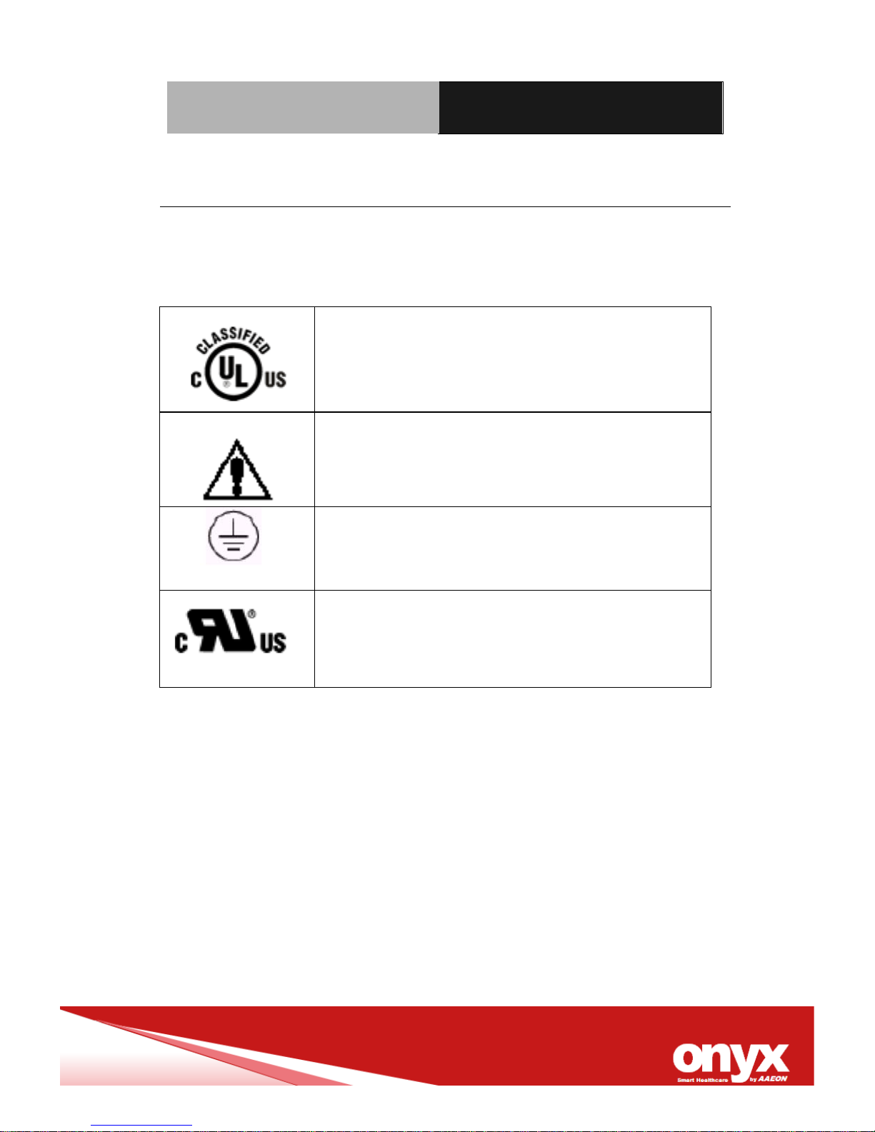
Safety Symbol Description
The following safety symbols are the further explanations for your
reference.
Medical equipment with respect to electric
shock, fire and mechanical hazards only in
accordance with UL 60601-1, and
CAN/CSA C22.2 NO. 601. 1
Attention, consult ACCOMPANYING
DOCUMENTS.
Ground wire
Protective Ground wire.
Medical equipment with respect to electric
shock, fire and mechanical hazards
only in
accordance with UL 60601-1, and
CAN/CSA C22.2 NO. 601. 1
Page 13

Medical PC MedPC- 5300
Contents
Chapter 1 General Information
1.1 Introduction ...................................................................... 1-2
1.2 Feature ............................................................................. 1-3
1.3 Specification ..................................................................... 1-4
1.4 Dimension ........................................................................ 1-6
Chapter 2 Hardware Introduction
2.1 Safety Precautions ........................................................... 2-2
2.2 A Quick Tour of MedPC5300………..……………………..2-2
2.3 System Memory ............................................................. 2-3
2.4 Mini PCI Ex pr es s ………………..………………...............2-8
2.5 Clear CMoS9CLTRC1.………………………………..……2-8
2.6 Rear Panel Connectors ……………………………..……2-10
2.7 Wallmount kit Installation………………………………….2-12
Chapter 3 BIOS Setup
3.1 BIOS Setup……………………… ……… ……… …… ……..3-1
Chapter 4 Driver Installation
4.1 Installation ........................................................................ 4-3
Appendix A I/O Information
A.1 I/O Address Map ............................................................. A-2
A.2 Memory Address Map ..................................................... A-3
A.3 IRQ Mapping Chart ....................................................... A-5
Page 14

Medical PC MedPC- 5300
Appendix B Miscellanea
B.1 General Cleaning Tips .................................................... B-2
B.2 Cleaning Tools ................................................................ B-3
B.3 Scrap Computer Recycling ........................................... B-5
Page 15

Medical PC MedPC- 5300
Chapter 1 General Information 1-1
General
Information
Chapter
1
Page 16

Medical PC MedPC- 5300
Chapter 1 General Information 1-2
1.1 Introduction
The MedPC-5300 is a Medical grad e embedded PC with Intel Atom
D525 processor-based computer. It is a PC-based embedded
system with IPX1 water proof system architecture and “Fan-less”
solution; integrated multimedia functions make them the perfect
platforms to build comprehensive computing applications.
The MedPC-5300 series is the all the features of a powerful
computer into a small chassis. The MedPC-5300 has
designed with
the next-generation NVIDIA® ION™ graphics to support richer
multi-media. 2 type video interface to support Full HD 1920 x 1080
resolution. It supports 2.5” Hard Disk Drive bay and one Mini card
for WLAN expansion. Moreover, they feature flexible I/O ports, such
as 5 USB 2.0, 2 RS-232, Single Giga LAN RJ-45 connector, one
VGA, one digital video port, one set audio (one Line Out, one MIC
In and Line in).
Convenient operation, fanless, compact size, low power
consumption and highly integrated multimedia system let you to
focus on healthcare utility, interactive information displays,
automation control systems, general desktop usage, multimedia
recreation, and other medical requirements.
Page 17

Medical PC MedPC- 5300
Chapter 1 General Information 1-3
1.2 Feature
MedPC-5300
♦ High Performance Intel Dual core D525 1.8GHz Processor
♦ Multiple display output support versatile dual display function
♦ Supports Mini card for WLAN(option)
♦ System chassis of easy clean design (no airhole)
♦ Top cover with IPX1 water proof protection
♦ Nvidia GT218 graphic engine inside
♦ Guarantee 5 years life time
♦ Isolated I/O interface (Optional)
♦ EN/UL 60601-1 & CE/FCC Class B
Page 18

Medical PC MedPC- 5300
Chapter 1 General Information 1-4
1.3 Specification
Main Specifications
CPU Intel Atom D525 DC 1.8GHz Processor
System Memory
DDR3 SODIMM x 2 204 pin supports DDRIII 1066/1333, Max. 8GB
Chipset Intel ICH8M
Expansion Mini Card x1
Storage Disk
Drive
2.5” SATA Hard Disk/SSD Drive bay x1, support SATA 3.0(6Gb/s)
Graphic Specifications
Chipset
NVIDIA GT218, Onboard DDR3 512MB Memory
Resolution VGA x 1 supports up to 2048 x 1536 (@85Hz ) ; Digit al outp ut
interface x 1, support 1920 x 1080
Audio Mic-in, Line-in, Line-out, 3 Phone jacks
USB USB 2.0 x 4, USB 2.0 x 1 with isolation(4KV)
Serial Port RS232 x 1, USB x 1 with isolation(4KV)
Ethernet GbE LAN x 1 by RJ-45
KB/MB 1 PS/2 for keyboard and mouse
Mechanical and Environmental
Power Requirement DC12V power input
Operating
Temperature
0˚C to 40˚C (32˚F~104˚F)
Storage Temperature -20˚C to 60˚C (-4˚F ~140˚F)
Mounting Desktop
Page 19

Medical PC MedPC- 5300
Chapter 1 General Information 1-5
Net Wet 5.6kg
EMC CE/FCC Class B
Page 20

Medical PC MedPC- 5300
Chapter 1 General Information 1-6
1.4 Dimension
MedPC-5300
Page 21

Medical PC MedPC- 5300
Chapter 1 General Information 1-7
Page 22

Medical PC MedPC- 5300
Chapter 2 Hardware Installation 2-1
Hardware
Introduction
Chapter
2
Page 23

Medical PC MedPC- 5300
Chapter 2 Hardware Installation 2-2
2.1 Safety Precautions
Always completely disconnect the power
cord from your board whenever you are
working on it.
Do not make connections while the power
is on, because a sudden rush of power
can damage sensitive electronic
components.
Always ground yourself to remove any
static charge before touching the board.
Modern electronic devices are very
sensitive to static electric charges; please
remember to use a grounding wrist strap
at all times.
Place all electronic components on a
static-dissipative surface or in a
static-shielded bag when they are not in
the chassis.
2.2 A Quick Tour of the MedPC-5300
Before you star t to set up the MedPC, tak e a moment to becom e
familiar with the locations and purposes of the CPU, Memory, MOS,
and connector and are illustrated in the figures below.
Front View of MedPC-5300
Page 24

Medical PC MedPC- 5300
Chapter 2 Hardware Installation 2-3
Rear view of MedPC-5300
2.3 System Memory
2.3.1 Overview
The motherboard comes with four 204-pin Double Data Rate 3
(DDR3) SO Dual Inline Memory Modules (DIMM) sockets. DDR3
SODIMMs are notched differently to prevent installation on a DDR2
SODIMM socket. The following figure illustrates the location of the
sockets:
Page 25

Medical PC MedPC- 5300
Chapter 2 Hardware Installation 2-4
204-Pin DDR3 SODIMM sockets
2.3.2 Memory Configurations
You may install 1 GB and 2 GB unbuffered ECC or non-ECC DDR3
SODIMMs into the SODIMM sockets using the memory
configurations in this section.
IF you installed two 2GB memory modules,
the system may detect less than 3GB of total
memory because of address space
allocation for other critical functions. This
limitation applies to Windows XP 32-bit
version operating system since it does not
support PAE (Physical Address Extensi on)
Page 26

Medical PC MedPC- 5300
Chapter 2 Hardware Installation 2-5
mode.
IF you install Windows XP 32-bit version
operating system, we recommend that you
install less than 3GB of total memory.
2.3.3 Installing a SO-DIMM
1. Unlock a DIMM socket by pressing the retaining clips outward.
2. Align a SO-DIMM on the socket such that the notch on the
SO-DIMM matches the break on the socket.
Page 27

Medical PC MedPC- 5300
Chapter 2 Hardware Installation 2-6
3. Firmly insert the SO-DIMM into the socket until the retaining
clips snap back in place and the SO-DIMM is properly seated.
Page 28

Medical PC MedPC- 5300
Chapter 2 Hardware Installation 2-7
The DDR3 SO-DIMM sockets do not
support DDR SO-DIMMs. DO NOT install
DDR2 SO-DIMMs to the DDR3 SO-DIMM
socket.
Make sure to unplug the power supply before
adding or removing SO-DIMMs or other system
components. Failure to do so may cause severe
damage to both the motherboard and the
components.
2.3.4 Removing a SO-DIMM
1. Simultaneously press the retaining clips downward to unlock
the DIMM.
2. Remove the DIMM from the socket.
Page 29

Medical PC MedPC- 5300
Chapter 2 Hardware Installation 2-8
This motherboard supports one MINI PCI Ex pres s . The following
figure shows a Decode card installed on the MINI PCI Express slot.
2.4 Mini PCI Express
2.5 Clear CMOS9CLTRC1
This jumper allows you to clear the Real Time Clock (RTC) RAM in
CMOS. You can clear the CMOS memory of date, time, and system
setup parameters by erasing the CMOS RTC RAM data. The
onboard button cell battery powers the RAM data in CMOS, which
includes system setup information such as system passwords.
To erase the RTC RAM:
1. Turn OFF the computer and unplug the power cord.
2. Remove the onboard battery.
3. Move the jumper cap from pins 1-2 (default) to pins 2-3. Keep
the cap on pins 2-3 for about 5~10 seconds, then move the cap
back to pins 1-2.
4. Re-install the battery.
Page 30

Medical PC MedPC- 5300
Chapter 2 Hardware Installation 2-9
5. Plug the power cord and turn ON the computer.
6. Hold down the <Del> key during the boot process and enter
BIOS setup to re-enter data.
Except when clearing the RTC RAM, never
remove the cap on CLRTC jumper default
position. Removing the cap will cause
system boot failure!
You do not need to clear the RTC when the
system hangs due to overclocking. For system
failure due to overclocking, use the C.P.R. (CPU
Parameter Recal l) feature. Shut dow n and reboot
the system so the BIOS can automatically reset
parameter settings to default values.
Page 31

Medical PC MedPC- 5300
Chapter 2 Hardware Installation 2-10
2.6 Rear Panel Connectors
1. DC-in power jack This port is for 12V DC power.
2. PS/2 keyboard mouse port This port is for a Y-Cable for
PS/2KB&Mouse.
3. Serial connector This 9-pin COM1 port is for serial devices.
4. HDMI port This 19-pin HDMI 1.3 port connect is for a HDMI
monitor.
5. VGA port This 15-pin VGA port connect is for a VGA monitor.
6. DVI-I port This 29-pin DVI-I (Dual link) port connect is for a HDMI
monitor.
7. USB 2.0 ports 0 ~ 3. These four 4-pin Universal Serial Bus (USB)
ports are available for connecting USB 2.0 devices.
8. LAN (RJ-45) port. This port allows Gigabit connection to a Local
Area Network (LAN) through a network hub. Refer to the table
below for the LAN port LED indications.
LAN port LED indications
Page 32

Medical PC MedPC- 5300
Chapter 2 Hardware Installation 2-11
9. Line In port (light blue). This port connects a tape, CD, DVD
player, or other audio sources.
10 Line Out port (lime). This port connects a headphone or a
speaker. In 4-channel, 6-channel, and 8-channel configuration,
the function of this port becomes Front Speaker Out.
11. Microphone port (pink). This port connects a microphone.
Page 33

Medical PC MedPC- 5300
Chapter 2 Hardware Installation 2-12
2.7 Rear Panel Connectors
Get the brackets ready and fasten appropriate three
screws on each bracket. After fastening the two brackets
on the bottom lid of MedPC-5300, the w a llm ount k it
installation is finished.
Page 34

Medical PC MedPC- 5300
Chapter 3 BIOS Setup 3-0
BIOS Setup
Chapter
3
Page 35

Medical PC MedPC- 5300
Chapter 3 BIOS Setup 3-1
3.1 BIOS Setup
3.1.1 BIOS Setup Program
This motherboard supports a programmable firmware chip that you
can update using the provided utility. Use the BIOS Setup program
when you are installing a motherboard, reconfiguring your system,
or prompted to “Run Setup.” This section explains how to configure
your system using this utility.
Even if you are not prompted to use the Setup program, you can
change the configuration of your computer in the future. For
example, you can enable the security password feature or change
the power management settings. This requires you to reconfigure
your system using the BIOS Setup program so that the computer
can recognize these changes and record them in the CMOS RAM of
the firmware hub.
The firmware hub on the motherboard stores the Setup utility. When
you start up the computer, the system provides you with the
opportunity to run this program. Press <Del> during the
Power-On-Self-Test (POST) to enter the Setup utility; otherwise,
POST continues with its test routines.
If you wish to enter Setup after POST , restart the system by pressing
Page 36

Medical PC MedPC- 5300
Chapter 3 BIOS Setup 3-2
<Ctrl + Alt + Delete>, or by pressing the reset button on the system
chassis. You can also restart by turning the system off and then
back on. Do this last option only if the first two failed.
The Setup program is designed to make it as easy to use as
possible. Being a menu-driven program, it lets you scroll through the
various sub-menus and make your selections from the available
options using the navigation keys.
The default BIOS settings for this
motherboard apply for most conditions to
ensure optimum performance. If the system
becomes unstable after changing any BIOS
settings, load the default settings to ensure
system compatibility and stability. Select the
Load Optimized Defaults from the BIOS
menu screen.
The BIOS setup screens shown in this
section are for reference purposes only, and
may not exactly match what you see on your
screen.
Visit the system builder’s website to
download the latest BIOS file for this
motherboard
3.1.2 Legend Box
The keys in the legend bar allow you to navigate through the various
setup menus
Key Function Description
Page 37

Medical PC MedPC- 5300
Chapter 3 BIOS Setup 3-3
← Select Screen
↑↓ Select Item
+ - Change Option / Field
Enter Go to Sub Screen
PGDN Next Page
PGUP Previous Page
F1 General Help
F2 Previous Values
F3 Optimized Defaults
F4 Save & Exit
ESC Exit
3.1.3 List Box
This box appears only in the opening screen. The box displays an
initial list of configurable items in the menu you selected.
3.1.4 Sub-menu
Note that a right pointer symbol appears to the left of certain
fields. This pointer indicates that you can display a sub-menu from
this field. A sub-menu contains additional options for a field
parameter. To display a sub-menu, move the highlight to the field
and press <Enter>. The sub‑menu appears. Use the legend keys to
enter values and move from field to field within a sub-menu as you
Page 38

Medical PC MedPC- 5300
Chapter 3 BIOS Setup 3-4
would within a menu. Use the <Esc> key to return to the main menu.
Page 39

Medical PC MedPC- 5300
Chapter 4 Driver Installation 4-1
Driver
Installation
Chapter
4
Page 40

Medical PC MedPC- 5300
Chapter 4 Driver Installation 4-2
The MedPC-5300 comes with an AutoRun CD-ROM that contai ns
all drivers and utilities that can help you to install the driver
automatically.
Insert the driver CD , the dri ver CD-t itle will aut o start and s how the
installation guid e. If not, pl e as e f ollo w the s eq uenc e be lo w to ins ta ll
the drivers.
Follow the sequence below to install the drivers:
Step 1 – Install Intel® INF Driver
Step 2 – Install Intel
®
VGA Driver
Step 3 – Install Intel
®
LAN Driver
Step 4 – Install Audio Driver
Step 5 – Install AHCI Driver
Please read instructions below for further detailed installations.
Page 41

Medical PC MedPC- 5300
Chapter 4 Driver Installation 4-3
4.1 Installation:
Insert the MedPC-5300 CD-ROM into the CD-ROM drive. And
install the drivers from Step 1 to Step 5 in order.
Step 1 – Install Intel
®
INF Driver
1. Click on the Step 1 – Inf Driver folder and double
click on the infinst911autol.exe
2. Follow the instructions that the window shows
3. The system will help you install the driver automatically
Step 2 – Install Intel
®
VGA Driver
1. Click on the Step 2 – VGA Driver folder and select
the OS folder your system is
2. Double click on the .exe file located in the OS folder
3. Follow the instructions that the window shows
4. The system will help you install the driver automatically
Step 3 – Insta ll I ntel LAN Driver
1. Click on the LAN driver folder and select the Winx32
folder and double click on .exe for XP (32bit) OSFollow
the instructions that the window shows
2. The system will help you install the driver automatically
Step 4 –Install Audio Driver
Page 42

Medical PC MedPC- 5300
Chapter 4 Driver Installation 4-4
1. Click on the Step 4 –AUDIO driver folder and select the
XP 32_64 folder for your operating system and double click
on Setup.exe file
2. Follow the instructions that the window shows
3. The system will help you install the driver automatically
Step 5 – Install AHCI Driver
1. Click on the XP 32bit folder and and s elect the iaAHIC
and double click on it
2. Follow the instructions that the window shows
3. The system will help you install the driver automatically
Page 43

Medical PC MedPC- 5300
Appendix A I/O Information A-1
I/O Information
Appendix
A
Page 44

Medical PC MedPC- 5300
Appendix A I/O Information A-2
A.1 I/O Address Map
Page 45

Medical PC MedPC- 5300
Appendix A I/O Information A-3
A.2 Memory Address Map
Page 46

Medical PC MedPC- 5300
Appendix A I/O Information A-4
Page 47

Medical PC MedPC- 5300
Appendix A I/O Information A-5
A.3 IRQ Mapping Chart
Page 48

Medical PC MedPC- 5300
Appendix A I/O Information A-6
Page 49

Medical PC MedPC- 5300
Appendix B Miscellanea B-1
Miscellanea
Appendix
B
Page 50

Medical PC MedPC- 5300
Appendix B Miscellanea B-2
B.1 General Cleaning Tips
You may need the following precautions before you begin to clean
the computer. When you clean any single part or component for the
computer, please read and understand the details below fully.
1. Never spray or squirt the liquids directly onto any computer
component. If you need to clean the device, please rub it
with a piece of dry cloth.
2. Be cautious of the tiny removable components when you
use a vacuum cleaner to absorb the dirt on the floor.
3. Turn the system off before you start to clean up the
component or computer.
4. Never drop the components inside the computer or get
circuit board damp or wet.
5. Be cautious of all kinds of cleaning solvents or chemicals
when you use it for the sake of cleaning. Some individuals
may be allergic to the ingredients.
6. Try not to put any food, drink or cigarette around the
computer.
Page 51

Medical PC MedPC- 5300
Appendix B Miscellanea B-3
B.2 Cleaning tool s
Although many companies have created products to help improve
the process of cleaning your computer and peripherals users can
also use household items to clean their computers and peripherals.
Below is a listing of items you ma y need or want to use while
cleaning your computer or computer peripherals.
Keep in mind that some components in your computer may only be
able to be cleaned using a product designed for cleaning that
component, if this is the case it will be mentioned in the cleaning
tips.
• Cloth - A piece of cloth is the best tool to use when rubbing
up a component. Although paper towels or tissues can be
used on most hardware as well, we still recommend you to
rub it with a piece of cloth.
• Water or rubbing alcohol – You may moisten a piece of
cloth a bit with some water or rubbing alcohol and rub it on
the computer. Unknown solvents may be harmful to the
plastics parts.
• Vacuum cleaner - Absorb the dust, dirt, hair, cigarette
particles, and other particles out of a computer can be one
of the best methods of cleaning a computer. Over time
these items can restrict the airflow in a computer and cause
circuitry to corrode.
Page 52

Medical PC MedPC- 5300
Appendix B Miscellanea B-4
• Cotton swabs - Cotton swaps moistened with rubbing
alcohol or water are excellent tools for wiping hard to reach
areas in your keyboard, mouse, and other locations.
• Foam swabs - Whenever possible it is better to use lint
free swabs such as foam swabs.
Note:
We strongly recommended that you should shut down the
system before you start to clean any single components.
Please follow the steps below.
1. Close all application programs
2. Close operating software
3. Turn off power switch
4. Remove all device
5. Pull out power cable
Page 53

Medical PC MedPC- 5300
Appendix B Miscellanea B-5
B.3 Scrap Computer Re cycling
If the computer equipments need the maintenance or are beyond
repair, we strongly recommended that you should inform us as
soon as possible for the suitable solution. For the computers that
are no longer useful or work well, please contact with worldwide
distributors for recycling.
The worldwide distributors show on the following website:
http://www.onyx-healthcare.com.tw/Contact.php
Note:
Follow the national requirements to dispose unit
 Loading...