

Page 1

ADR2010
ANALOG/DIGITALRS232/RS485
INTERFACE
USER MANUAL
V 3.0
Caution: The ADR2010 is a static sensitive device. Observe proper procedures
for handling static sensitive devices.
ONTRAK CONTROL SYSTEMS INC.
764 Notre Dame Avenue
Unit # 1
Sudbury Ontario
CANADA P3A 2T2
(705) 671-2652 ( VOICE )
(705) 671-6127 ( FAX )
www.ontrak.net ( WEB )
Page 2

Ontrak Control Systems Inc. reserves the right to change product specifications to improve the
product.
Although every attempt has been made to insure accuracy of information contained in this
manual, Ontrak Control Systems Inc. assumes no liability for inadvertent errors.
Warranty: This ADR2010 is warranted from defects in workmanship and materials for a period of
90 days. Liability for defects is limited to the purchase price of the product. This warranty shall not
apply to defects resulting from improper modifications or use outside published specifications.
Hyperterminal and Windows are trademarks of Microsoft Corporation.
APPLE , MACINTOSH and MAC are trademarks of Apple Computer Inc.
PC, XT, AT, PS/2 are trademarks of International Business Machines Inc.
COPYRIGHT 1999 ONTRAK CONTROL SYSTEMS INC.
Page 3

TABLE OF CONTENTS
READ ME FIRST 3
1. Communication options.
a) The ADR2010 RS232 Interface. 4
b) The ADR2010 RS485 Interface 5
2. Powering the ADR2010 5
3. ADR2010 Commands 6
a) Analog Input Commands 7
b) PWM Output Commands 8
c) Digital Port Commands 9
d) Event Counter Commands 10
e) ID Command 10
4. Using BASIC with ADR Products 11
5. Using TURBO C with ADR Products 12
6. Daisy Chain Options for ADR2000 Series Products 15
7. Interfacing to the ADR2010 ( basic examples )
a) Reading Potentiometer Position 16
b) Connecting Switches to Digital Ports 17
c) Connecting LED'S to Digital Ports 18
d) Driving Solid-State Relays 18
e) Solid-state Temperature Measurement 19
f) Event-Counter Connections 20
8. Calibration Procedures 20
APPENDIX
A-CONNECTION DIAGRAM 21
B-ELECTRICAL SPECIFICATIONS 22
C-MOUNTING DIMENSIONS 23
ONTRAK CONTROL SYSTEMS INC. 2/23 www.ontrak.net
Page 4

READ ME FIRST
Thank you for purchasing this ADR2010 serial data acquisition interface. There
are three steps to using the ADR2010.
1.Connecting your computer or terminal to the ADR2010.
2.Providing power to the ADR2010.
3.Sending commands to the ADR2010.
This manual will provide guidance for completing these steps along with BASIC
and TURBO C programming tips. An applications section is also provided to
describe how to interface various electronic transducers and other devices to the
ADR2010. Additional applications and programming examples are available on
our web page at http://www.ontrak.net/
FEATURES
-8, 12-bit analog inputs ( 0 -5 VDC , 0-10VDC, +/- 5 VDC, +/-10VDC )
- 2 PWM outputs
-16-bit contact or TTL input event counter
-8 digital I/O lines individually programmable as input or output
-high current digital I/O lines ( sink 20mA/source 20mA )
-on-board RS232 to RS485 converter
-daisy-chainable up to 10 boards
-daisy-chainable power supply
-low power requirements ( 5 volts at 40mA )
-power-up via standard wall adapter ( optional )
-simple yet versatile commands
-easy to use with Visual BASIC or TURBO C programs
-compatible with all ADR2000 series interfaces
ONTRAK CONTROL SYSTEMS INC. 3/23 www.ontrak.net
Page 5
1a)THE ADR2010 RS232 INTERFACE
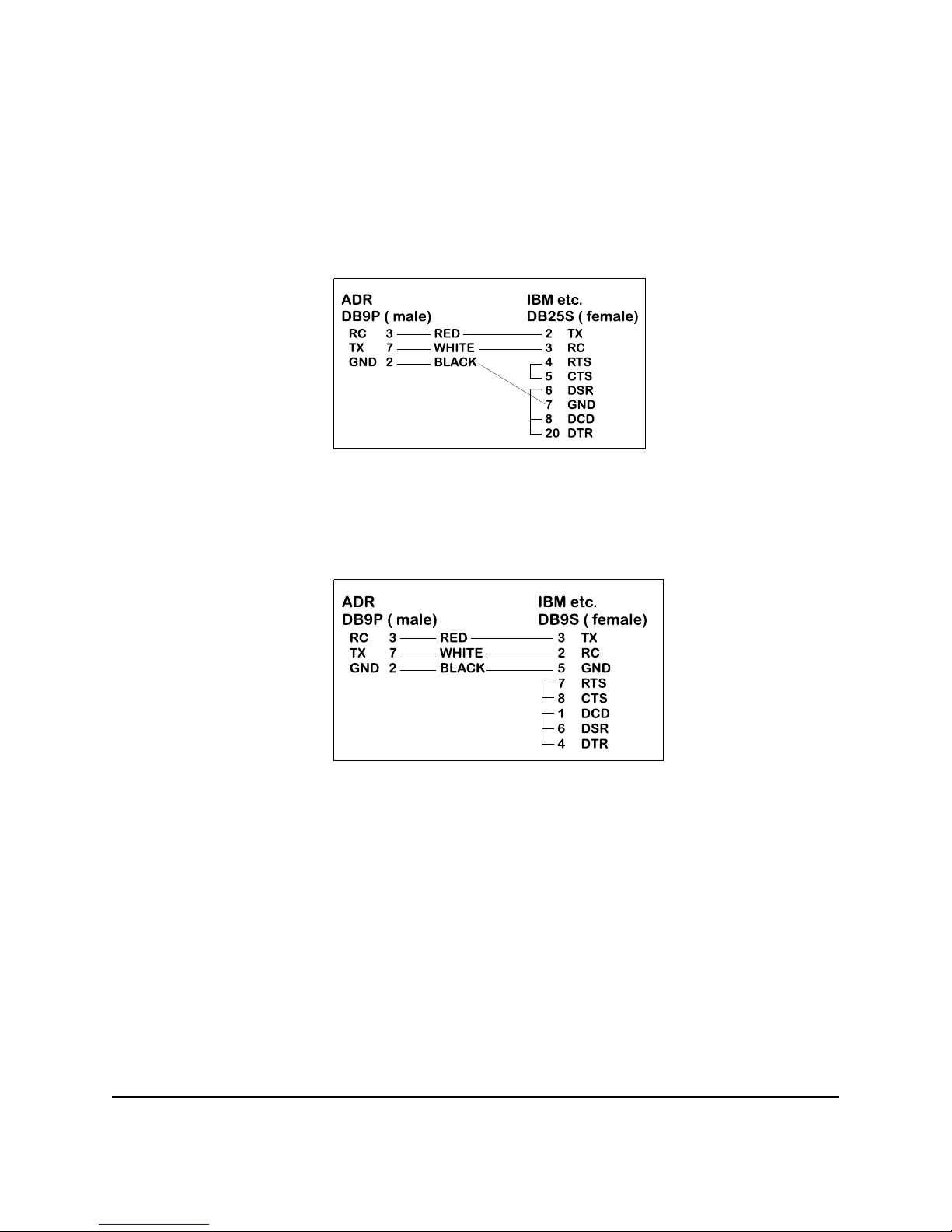
The ADR2010 communicates via a standard RS232 port utilizing a simple three-wire interface.
The only signals used are received data (RC), transmitted data (TX) and ground (GND). Most
RS232 ports use hardware handshaking (i.e. DTR, DSR, CTS, RTS) signals to control the flow of
data on the port. For this reason the cable required to connect to the ADR2010 must have
jumpers on the DB25 end to satisfy these handshaking requirements. IBM or compatible
computers may be used as a host computer with the supplied cable. The supplied cable has the
following connections;
Figure 1: Supplied Cable Wiring Diagram
If the host computer has a 9-pin serial port connector, a 9-pin to 25-pin adapter cable will be
required to connect to the ADR2010 cable. This adaptor is available at most computer dealers. If
possible, the DB25 connector on the supplied cable may be removed and a female DB9S
connector can be soldered in its place using the following wiring diagram;
Figure 2 : Modified Wiring Diagram For 9-PIN SERIAL PORTS
If the host computer has a female DB25 connector, a male-to-male adapter is required to use the
supplied cable. This may be purchased at most computer dealers. Apple Macintosh computers
may be connected to the ADR2010 using MAC to DB25 DTE conversion cable.
Once connected to the RS232 based host computer or terminal, the RS232 port should be
configured to the following specifications to allow communication with the ADR2010.
9600 baud - 8 bit words - 1 stop bit - no parity
If using BASIC or C consult the appropriate section in this manual for details on how to configure
your serial port. If a terminal or terminal emulation program is used, configure your terminal to the
above specifications using the operations manual for your terminal equipment or terminal
emulation program.
ONTRAK CONTROL SYSTEMS INC. 4/23 www.ontrak.net
Page 6
1b)THE ADR2010 RS485 INTERFACE
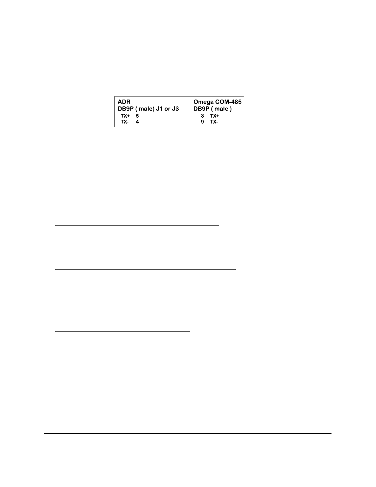
The ADR2010 RS485 interface is a two-wire connection meeting all the standards of the EIA
RS485 interface specifications. The supplied cable is NOT an RS485 cable. To com municate via
RS485 the host computer must have an RS485 port and be connected directly with two wires (
TR+ and TR-). A typical connection diagram is shown in figure 2.
Figure 2 :Typical RS485 Connection
Note that both J1 and J3 are RS485 compatible ports. Connection from the host to the ADR2010
should be made using J1 and then J3 is used to enable daisy chaining additional ADR2000 series
products.
The host RS485 port should be configured with the following specifications to enable
communications to the ADR2010, 9600 Baud - 8 bit words - 1 stop bit - no parity.
Line feeds should NOT be sent after commands as they may collide with data being returned from
the ADR2010.
2.PROVIDING POWER TO THE ADR2010
The ADR2010 may be powered using a regulated 5 volt power supply or a suitable wall adaptor.
Power to daisy chained ADR2010 may also be supplied via the daisy chain cable. See the Daisy
chaining section of this manual for further information.
POWER-UP USING A 5 VOLT REGULATED SUPPLY
If the ADR2010 is to be powered using a regulated 5 volt power supply, the 5VDC and GND
connections are to be made to the ADR2010 via the main terminal block TB1. The supply must be
able to provide a minimum of 60mA and up to 240mA if the ADR2010 is to source current from the
digital outputs. Care must be taken to avoid improper power supply connection as
perm anent damage to the ADR2010 m ay result if connected improperly. No connection to J2
is to be made if the ADR2010 is powered by a regulated 5 volt supply.
POWER-UP USING A WALL ADAPTOR
The ADR2010 has an on-board 5 volt regulator allowing the use of a 9-volt wall adaptor to power
the internal circuits. The regulator should be able to provide from 300-500mA .(MODE 68-950-1)
The regulator must have a standard 2.1mm, center negative, coaxial connector. The connector
can then be inserted into J2 on the ADR2010. When the ADR2010 is powered by a wall adaptor,
the on-board regulator also may provide a regulated 5 volts DC out to provide power to external
circuits. This 5 volt supply is available on TB1. The amount of current available depends on the
amount of current sourced by the digital ports. For safe operation no more than 100m A should
be draw n from the pow er term inals to pow er external circuits.
ONTRAK CONTROL SYSTEMS INC. 5/23 www.ontrak.net
Page 7

ANALOG INPUT COMMAND SUMMARY
RD Returns status of all 8 analog inputs in decimal form at ( 0 - 5VDC Ref. )
RB Returns status of all 8 analog inputs in decimal format ( +/- 5VDC Ref. )
RT Returns status of all 8 analog inputs in decimal form at ( 0 - 10VDC Ref. )
RH Returns status of all 8 analog inputs in decimal format ( +/- 10VDC Ref. )
RDn Returns status of analog port specified by n in decimal format.
Input range 0 - 5VDC, ( n = 0 to 7 )
RBn Returns status of analog port specified by n in decimal format.
Input range +/- 5VDC, ( n = 0 to 7 )
RTn Returns status of analog port specified by n in decimal format
Input range 0 - 10VDC,( n = 0 to 7 )
RHn Returns status of analog port specified by n in decimal format
Input range +/- 10VDC, ( n = 0 to 7)
ANALOG OUTPUT COMMAND SUMMARY
FH Sets frequency for PWM outputs to 9.76Khz
FM Sets frequency for PWM outputs to 2.44Khz
FL Sets frequency for PWM outputs to 610 Hz
EA Enables 10-bit PWM output on Terminal V1
EB Enables 10-bit PWM output on Terminal V2
DA Disables 10-bit PWM output on Terminal V1
DB Disables 10-bit PWM output on Terminal V2
TAdddd Sets period of PWM module A
TBdddd Sets period of PWM module B
DIGITAL COMMAND SUMMARY
CPAxxxxxxxx Configures PORT A. (x=1 for input, x=0 for output)
SPAxxxxxxxx Output binary data to PORT A. ( x=1 or 0 )
RPA Returns status of all I/O lines in PORT A in binary format.
RPAn Returns status of I/O line specified by n. (n= 0 to 7 )
MAddd Outputs decimal data (ddd) to PORT A. (ddd= 0 to 255 )
PA Returns status of PORT A in decimal format.
RESPAn Resets I/O line specified by n in PORT A. ( n= 0 to 7 )
SETPAn Sets I/O line specified by n in PORT A. ( n= 0 to 7 )
EVENT COUNTER COMMAND SUMMARY
CE Clear Event Counter.
RE Returns present count of counter.
REC Returns present count of counter and clears event counter.
ID COMMAND
*IDN? Returns 4 digit product identifier code. ( 2010 )
ONTRAK CONTROL SYSTEMS INC. 6/23 www.ontrak.net
Page 8

3. ADR2010 COMMANDS
a) ANALOG INPUT COMMANDS
There are 8 analog inputs, with a resolution of 12-bits, on the ADR2010 labeled AN0 to AN7. The
analog input range is 0-5 VD C , 0-10VDC, +/- 5VDC, or +/- 10VDC. The input range is
automatically selected by the command used to read a specific port. No jumpers need to be set
and all analog inputs may have positive or negative voltages present whether they are read in
unipolar or bipolar mode.
Analog Array Read Commands,
RD Reads all eight analog inputs in unipolar mode ( 0-5VDC ) and returns 8 values in
decimal format. Data separator is space ( 20HEX ) returning 40 characters total.
Order is AN0 to AN7 ( voltage = ( reading / 4095 ) X 5 )
example; RD<cr>
3456 4095 1287 3212 2865 3577 1000 2321
( AN0=3456 ( 4.219V ), AN1=4095 ( 5.00V ), AN2=1287 ( 1.571V ),etc. )
RB Reads all eight analog inputs in bipolar mode ( +/-5VDC ) and returns 8 values in
decimal format. Data separator is space ( 20HEX ) returning 40 characters total.
Order is AN0 to AN7 ( voltage = ( ( reading/4095 ) X 10 ) -5 )
example; RB<cr>
3476 0023 1256 3210 1265 4095 0000 3541
( AN0=3476 ( 3.488V ), AN1=0023 ( -4.934V ), AN2=1256 ( -1.932V ),etc. )
RT Reads all eight analog inputs in unipolar mode ( 0-10VDC ) and returns 8 values
in decimal format. Data separator is space ( 20HEX ) returning 40 characters
total. Order is AN0 to AN7 ( voltage = ( reading/4095 ) X 10 )
example; RT<cr>
2476 1023 2056 3220 3285 4095 0000 1101
( AN0=2476 ( 6.046V ), AN1=1023 ( 2.498V ), AN2=2056 ( 5.021V ),etc. )
RH Reads all eight analog inputs in bipolar mode ( +/-10VDC ) and returns 8 values
in decimal format. Data separator is space ( 20HEX ) returning 40 characters
total. Order is AN0 to AN7 ( voltage = ( ( reading/4095 ) X 20 ) -10 )
example; RH<cr>
3116 0123 2346 3610 1005 4095 0000 0041
( AN0=3116 ( 5.219V ), AN1=0123 ( -9.399V ), AN2=2346 ( 1.458V ),etc. )
Single Channel Read Commands,
RDn Returns status of analog port specified by n in decimal format. ( n = 0 to 7 )
(Input voltage range is 0 to 5VDC)( voltage = ( reading / 4095 ) X 5 )
example; RD0<CR>
2356
( AN0 =2.877V )
ONTRAK CONTROL SYSTEMS INC. 7/23 www.ontrak.net
Page 9

RBn Returns status of analog port specified by n in decimal format. ( n = 0 to 7 )
(Input voltage range is (-5) to 5 VDC)( voltage = ( ( reading/4095 ) X 10 ) -5 )
example; RB3<CR>
1866
( AN3 = - 0.443V )
RTn Returns status of analog port specified by n in decimal format. ( n = 0 to 7 )
(Input voltage range is 0 to 10 VDC)( voltage = ( reading/4095 ) X 10 )
example; RT5<CR>
3003
( AN5 = - 7.333V )
RHn Returns status of analog port specified by n in decimal format. ( n = 0 to 7 )
(Input voltage range is (-10) to 10 VDC)( voltage = ( ( reading/4095 ) X 20 ) -10 )
example; RH1<CR>
1855
( AN1 = - 0.940V )
b) PWM OUTPUT COMMANDS
The ADR2010 has two PWM outputs on terminals V1 and V2.
The PWM modules on the ADR2010 boards can operate at three fixed output frequencies. Both
modules must operate at the same frequency and this frequency is set by the FH,FM and FL
commands
FH Sets frequency for PWM outputs to 9.76Khz
FM Sets frequency for PWM outputs to 2.44Khz
FL Sets frequency for PWM outputs to 610.Hz.
Note: if frequency is not set, default frequency is 610 Hz.
EA Turns on PWM output to Terminal V1
EB Turns on PWM output to Terminal V2
DA Disables PWM output on Terminal V1 ( V1 = high impedance )
DB Disables PWM output on Terminal V2 ( V2 = high impedance )
Note1: When PW M pins are disabled they are put into high impedance state.
TAdddd Sets the period of PWM output A on terminal V1 ( dddd=0000 to 1024 )
( 0000 = 0% 1024 = 100% )
example; TA512<CR>
period is set to 512/1024 = 50%
ONTRAK CONTROL SYSTEMS INC. 8/23 www.ontrak.net
Page 10

TBdddd Sets the period of PWM output B on terminal V2 ( dddd=0000 to 1024 )
( 0000 = 0% 1024 = 100% )
example; TB232<CR>
period is set to 232/1024 = 22.65%
c) DIGITAL PORT COMMANDS
There is one, eight bit digital port on the ADR2010 labeled PORT A. The individual I/O lines are
labeled PA0-PA7. The following commands allow the user to;
-configure individual bits an input or output
-SET or RESET individual bits
-read individual bits
-read entire port in binary or decimal format
-write to entire port in binary or decimal form at.
The digital port commands are;
CPAxxxxxxxx Configures each bit of PORT A . All eight bits must be specified. Order
is MSB-LSB ( x=1 for input, x=0 for output )
example; CPA11110000<CR>
( PA7 ,PA6, PA5, PA4 are configured as inputs and PA3, PA2, PA1, PA0 are
configured as outputs )
SPAxxxxxxxx Outputs binary data to PORT A. All eight bits must be specified.
Order is MSB-LSB. Individual bits configured as input are not
effected by this command. (x=1 or 0 )
example; SPA10101000<CR>
( PA7, PA5, PA3 are set, PA6, PA4, PA2, PA1, PA0 are reset )
RPA Returns status of all I/O lines in PORT A in binary format. Order is MSB-LSB.
Individual lines configured as output will return last data set on the port.
example; RPA<CR>
0 1 1 1 0 0 1 0
( PA7, PA3, PA2, PA0 are low, PA6, PA5 ,PA4, PA1 are high )
RPAn Returns status of I/O line in PORT A specified by n.( n=0 to 7 )
example; RPA4<CR>
1
( PA4 is high )
MAddd Outputs decimal data (ddd) to PORT A. Individual lines configured as
input are not effected by this command. (ddd= 000 to 255 )
example; MA255<CR>
ONTRAK CONTROL SYSTEMS INC. 9/23 www.ontrak.net
Page 11

( All lines of PORT A are set )
PA Returns status of PORT A in decimal format. Individual lines configured as
output will return last data set on PORT A.
example; PA<CR>
128
( PA7 is high, PA6 thru PA0 are low )
RESPAn Resets I/O line specified by n in PORT A. This command has no effect on I/O
lines configured as input. ( n=0 to 7 )
example; RESPA4<CR>
( PA4 is reset )
SETPAn Sets I/O line specified by n in PORT A. This command has no effect on I/O
lines configured as input. ( n=0 to 7)
example; SETPA3<CR>
( PA3 is set )
d) EVENT COUNTER COMMANDS
The ADR2010 is equipped with a 16-bit event counter that accepts TTL or contact input.
There are three commands available to read, and clear the event counter. If the maximum count
of 65535 is reached the counter will rollover to 00000 .
RE Returns decimal value of event counter
example; RE<CR>
00456
( Present count is 456.)
CE Clears event counter
example; CE<CR>
( Event counter is cleared to 00000 )
REC Reads and clears event counter
example; REC<CR>
12034
( Count is returned ( 12034 ) and counter is reset to 00000. )
E) ID COMMAND
*IDN? Returns ID code (2010 )
* may be omitted
ONTRAK CONTROL SYSTEMS INC. 10/23 www.ontrak.net
Page 12

4.SENDING COMMANDS IN BASIC TO THE ADR2010
OPENING A SERIAL FILE
Commands may be sent to the ADR2010 using a terminal emulation program such as
Hyperterminal by simply entering commands and pressing <cr>. With BASIC, the ADR2010 is
connected to the computer via a serial cable and BASIC treats the ADR2010 as a serial file.
Before commands can be sent to the ADR2010 this serial file must be opened and initialized. This
should be done at the start of any program that is to access the ADR2010. The command to open
a serial file is shown below;
10 OPEN "COM1:9600,n,8,1,CS,DS,RS" AS#1
This line opens a serial file and labels it as serial file #1. This allows access to the ADR2010 using
PRINT#1 and INPUT#1 commands.
SENDING COMMANDS
Sending commands in BASIC to the ADR2010 can be done using PRINT#1 commands. For
example, sending an RD0 command could be done as shown below;
20 PRINT#1, "RD0"
Extra spaces inside the quotes are ignored by the ADR2010. Avoid sending commands on
consecutive lines because a <CR> is not sent after the first command resulting in an
unrecognized command. This problem arises with the configuring of a digital port and then trying
to access the port immediately after it is configured. A REM statement should be inserted between
consecutive PRINT#1 commands as shown below;
20 PRINT#1, "CPA00000000"
30 REM FORCES <CR>
40 PRINT#1, "SETPA0"
Variable names may also be used with PRINT#1 commands. One example of this shown below.
This program configures PORT A as output and the increments it from 0 to 255.
10 OPEN "COM1:9600,n,8,1,CS,DS,RS" AS#1
20 PRINT#1, "CPA00000000"
30 FOR X = 0 to 255
40 PRINT#1, "MA",X
50 NEXT X
60 END
RECEIVING DATA
When reading analog inputs or the digital port, data is sent from the ADR2010 to the host
computers serial buffer. This data can be retrieved using INPUT#1 commands. The INPUT#1
command should be used following PRINT#1 commands if data is expected to be sent by the
ADR2010. If a single piece of data is expected then one variable name should be used with the
INPUT#1 command. If eight pieces of data are to be received as with the RPA command then
eight variable names must be used with the INPUT#1 command. Examples of both cases are
shown below;
ONTRAK CONTROL SYSTEMS INC. 11/23 www.ontrak.net
Page 13

20 PRINT#1, "RA0"
30 INPUT#1, ANADAT
40 PRINT#1, "RPA"
50 INPUT#1, PA7,PA6,PA5,PA4,PA3,PA2,PA1,PA0
The variable names used in the INPUT#1 commands now contain the data sent by the ADR2010
The data can now be scaled, printed, displayed, saved or whatever is required by the application.
A BASIC PROGRAM EXAMPLE
A complete BASIC program which reads analog port 0 and sets PA0 if the analog port is above
decimal value 2048 ( 2.5 volts ) is shown below;
10 OPEN "COM1:9600,n,8,1,CS,DS,RS" AS#1 ;opens and configures serial file
20 PRINT#1, "CPA11111110" ;configures PA0 as output
30 REM FORCES <CR>
40 PRINT#1, "RESPA0" ;resets PA0
50 REM FORCES <CR>
50 PRINT#1, "RD0" ;sends RD0 command
60 INPUT#1, AN0 ;receives data into variable AN0
70 IF AN0>2048 then PRINT#1, "SETPA0":GOTO 50 ;sends SETPA0 command if
AN0>50% and returns to line 50
80 PRINT#1, "RESPA0" : GOTO 50 ;resets PA0 and returns to 50
Visit our web page at www.ontrak.net for additional programming examples in BASIC, Visual
Basic and C.
5) SENDING COMMANDS IN TURBO C TO THE ADR2010
This section will demonstrate how to send and receive data from the ADR2010 using TURBO C.
It outlines the commands used to, configure the serial port (bioscom), send data out through the
serial port (fprintf), and receive data through the serial port (fscanf).
Commands used in TURBO C to access the ADR2010 require the following include files to be
declared at the start of TURBO C programs;
#include <stdio.h>
#include <bios.h>
CONFIGURING THE SERIAL PORT
The first step in accessing the ADR2010 via the serial port is configuring the serial port to the
proper communication parameters which are, 9600 baud, 8 bit words, no parity. This is done using
the "bioscom" command. The syntax for this command is;
bioscom (0,settings,com1);
where settings is previously defined as HEX E3 and com1 is defined as 0. Defining "settings" and
"com1" should be done using;
#define com1 0
#define settings (0xE3)
ONTRAK CONTROL SYSTEMS INC. 12/23 www.ontrak.net
Page 14

These statements should be placed immediately following your include files (see programming
examples). The bioscom comm and needs only to be executed once before the ADR2010 is
accessed.
SENDING COMMANDS TO THE ADR2010
To send commands to the ADR2010 the "fprintf" command is used. For example, the following
command sends an RD0 ( read analog port 0 ) command to the ADR2010;
fprintf (stdaux,"RD0 \xD");
The \xD suffix sends a carriage return after the command which is needed by the ADR2010 to
recognize a command. Integer variables may also be used in the command line. For example, the
following command sends a MAddd ( make port A=ddd ) command, where DOUT is a previously
defined integer value of 0 to 255.
fprintf (stdaux,"MA %d \xD",DOUT);
RECEIVING DATA FROM THE ADR2010
If a command sent to the ADR2010 is a responsive command, that is, one that results in data
being sent back to the host, the data is retrieved using the "fscanf" command. After this command
is used the serial buffer must be re-initialized using the "rewind" command. The syntax for this
command is;
rewind (stdaux);
This command is executed after data is retrieved using the "fscanf" command. For example, the
following commands send a RD0 command and stores the retrieved data in an integer variable
named AN0;
fprintf (stdaux,"RD0 \xD");
fscanf (stdaux,"%D",&an0);
rewind (stdaux);
In this example, the com mand PA ( read port A )is sent to the ADR2010 and the retrieved data is
stored in an integer variable named PORTA;
fprintf (stdaux,"PA \xD");
fscanf (stdaux,"%D",&PORTA);
rewind (stdaux);
The following test programs outline the proper syntax for using the com mands in simple
applications. The first program retrieves the status of analog port 0 and displays the data on the
video screen. The second program configures PORT A as output, sets the port to decimal 255,
reads back the port status and displays the data on the video screen.
ONTRAK CONTROL SYSTEMS INC. 13/23 www.ontrak.net
Page 15

/* PROGRAM EXAMPLE ONE - ANALOG PORT TEST PROGRAM */
#include <stdio.h>
#include <bois.h>
#define com1 0
#define settings (0xE3)
main( )
{ /* declare an0 as an integer number */
int an0 ;
/* configure com1 9600 baud, 8 bit words, no parity */
bioscom (0,settings,com1);
/* send RD0 command to ADR2010 on com1 */
fprintf(stdaux,"RD0 \xD");
/* read data from com1 and store it at address of an0 */
fscanf (stdaux,"%d",&an0);
/* initialize com1 buffer */
rewind (stdaux);
/* print data on screen */
printf ("ANALOG PORT 0= %d \n",an0);
}
/* PROGRAM EXAMPLE TWO - DIGITAL PORT TEST PROGRAM */
#include <stdio.h>
#include <bois.h>
#define com1 0
#define settings (0xE3)
main ( )
{ /* declare PORTA and DOUT as integer numbers */
int PORTA,DOUT ;
/* set DOUT to integer 255 */
DOUT=255;
/* configure com1 9600 baud, 8 bit words, no parity */
bioscom (0,settings,com1);
/* send CPA00000000 command to ADR2010 on com1 */
fprintf (stdaux,"CPA00000000 \xD");
/* send MAddd (ddd=DOUT) command to ADR2010 on com1 */
fprintf (stdaux,MA %d \xD",DOUT );
/* send PA command to ADR2010 on com1 */
fprintf (stdaux,"PA \xD");
/* read data from com1 and store at address of PORTA */
fscanf (stdaux,"%d",&PORTA );
/* initialize com1 buffer */
rewind (stdaux)
/* print data on screen */
printf ("PORT A is %d DECIMAL \n",PORTA);
}
ONTRAK CONTROL SYSTEMS INC. 14/23 www.ontrak.net
Page 16
6. Daisy Chain Options for the ADR2000 Series Products
Daisy chaining ADR2000 series boards involves three steps.
A. Setting Address Jumpers
B. Physically Connecting Boards
C. Sending commands
A. Setting Address Jumpers
The ADR2000 series products can be daisy-chained, regardless of the type of serial interface
provided by the host computer. Each board on the chain must be assigned an address via the
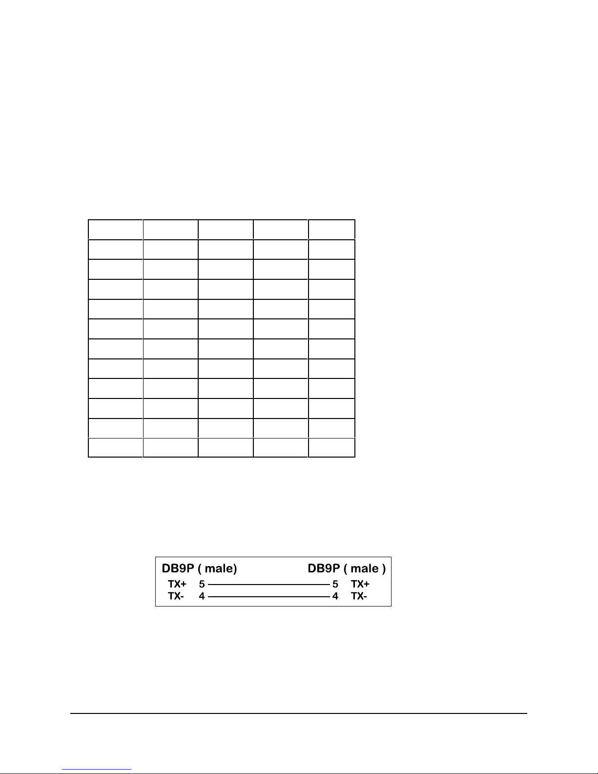
BCD address jumper block on the ADR2000 series product. Up to ten boards may be daisychained. The following table shows how to jumper the address jumper block to select a board
address.
Position 8 Position 4 Position 2 Position 1 Address
OPEN OPEN OPEN OPEN 0
OPEN OPEN OPEN JUMP 1
OPEN OPEN JUMP OPEN 2
OPEN OPEN JUMP JUMP 3
OPEN JUMP OPEN OPEN 4
OPEN JUMP OPEN JUMP 5
OPEN JUMP JUMP OPEN 6
OPEN JUMP JUMP JUMP 7
JUMP OPEN OPEN OPEN 8
JUMP OPEN OPEN JUMP 9
Table 1. Address Jumper Settings.
B. Physically Connecting Boards
The ADR2000 series interface boards have two DB9 connectors that allow daisy chaining. The
data format used in daisy chaining is RS485 regardless of the host communication type. To
connect boards on a chain, a daisy chain cable must be constructed. The cable must provide two
connections for the RS485 signals. A typical daisy-chain cable is shown in Figure 5a)
Figure 5a): Daisy-chain cable
Power may be shared in daisy-chained ADR2000 series interfaces if two extra conductors are
added to the daisy-chain cable. Care should be taken that the output current limitation on the
power supply is not exceeded. The connections for a powered daisy-chain cable are shown in
Figure 5B) NOTE: Power sharing is available only if power is applied via J2 ( 7-15VDC ).
ONTRAK CONTROL SYSTEMS INC. 15/23 www.ontrak.net
Page 17
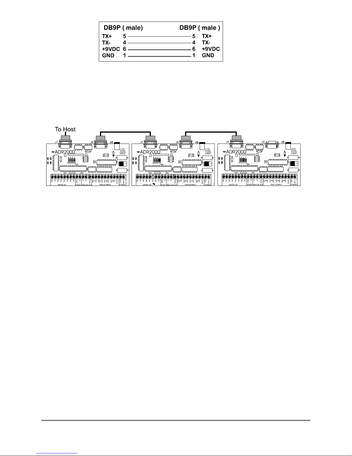
Figure 5b) : Powered Daisy-Chain Cable
The Daisy-chain cable can be connected from J3 to either J1 or J3 on additional ADR2000 series
interfaces. Both J1 and J3 have identical pinouts for RS485 and power signals used for daisychain applications. Figure 5c) shows a typical daisy-chain application. If a Powered daisy-chain
cable is used, power need only be connected to J2 on any one ADR2000 product in the chain.
Figure 5c) Typical Daisy-Chain Application
C Sending Commands
Once a board is jumpered, it will respond only to com mands preceded by its address as a single
digit integer number. For example to read analog port 0 on board 3 the command “3RD0"<cr> is
sent. To set PA4 on board 7 the command “7SETPA4",cr> is sent. Spaces sent between the
board address and commands are ignored. Board zero will respond to both commands with no
preceding address and commands preceded with a zero for reasons of continuity. Never connect
two boards with the same address on the same chain. This will result in both boards responding at
the same time and will cause contention on the network with possible damage to the ADR boards.
7. Interfacing to the ADR2010 ( Basic Examples )
The following interface examples show basic examples of interfacing various devices to the
ADR2000A, ADR2000B and ADR2010. Sample programs are written in BASIC and demonstrate
proper command syntax.
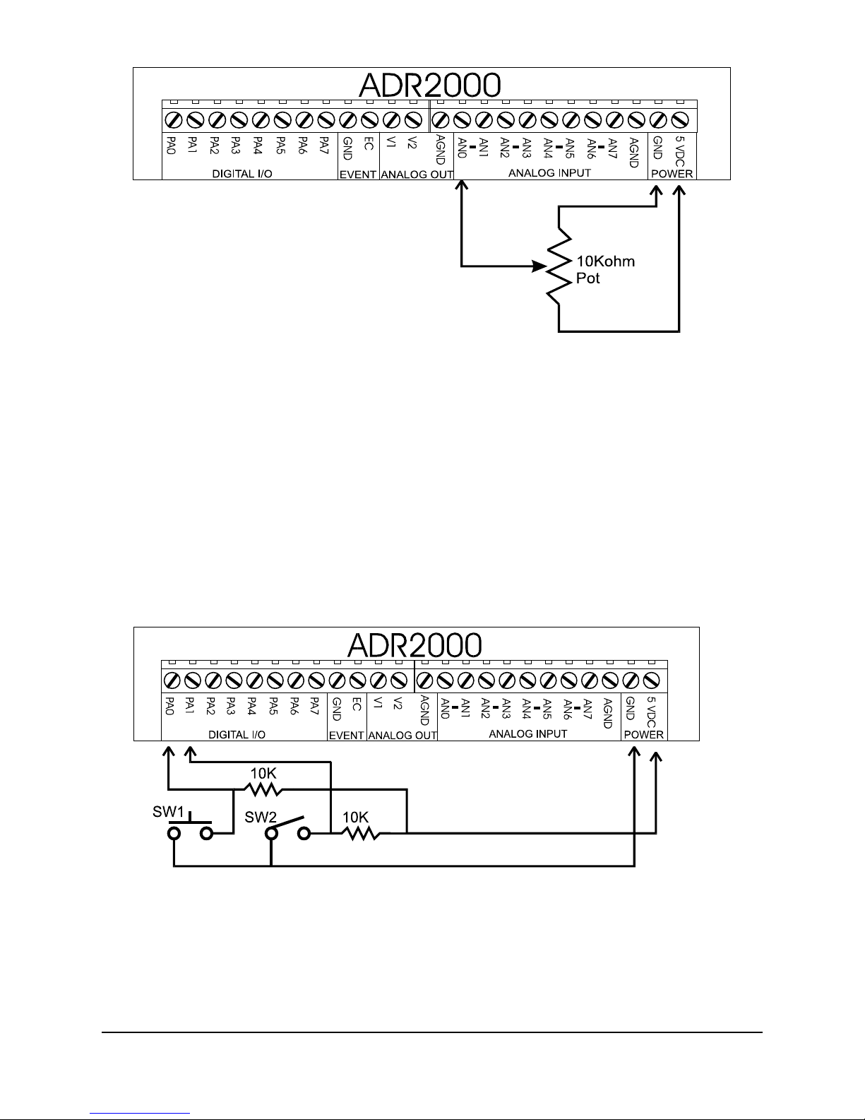
A) Reading Potentiometer Position
To monitor potentiometer position, the potentiometer must be biased with 5VDC. The wiper of the
pot is then connected to one of the analog inputs. The sample BASIC program reads the
potentiometer position using the RD0 command which responds with a decimal value between
0000 and 4095. The value is then converted to a percent and displayed on the video screen.
ONTRAK CONTROL SYSTEMS INC. 16/23 www.ontrak.net
Page 18
10 OPEN”COM1:9600,N,8,1,CS,DS,RS” AS#1 ;open com port
20 CLS ;clear screen
30 LOCATE 1,1 ;locate cursor
40 PRINT#1, “RD0" ;send RD0 command to ADR2000
50 INPUT#1, POT ;retrieve data from ADR2000
60 POT=(POT/4095)*100 ;convert data to percent
70 PRIN T “Potentiometer Position is”, POT ;display it
80 GOTO 30 ;repeat procedure
B) Connecting Sw itches to Digital Ports
To connect switches to digital I/O lines only one additional component is required. Each digital
input line used to read a switch must be tied to +5V via a 10Kohm resistor. This is to avoid leaving
the digital port floating when the switch is in the open position. The switch is then connected
between the digital port and ground. The sample BASIC program first configures the digital I/O
lines as input and then reads the switches and displays their status on the video screen.
10 OPEN “COM1:9600,N,8,1,CS,DS,RS” AS#1 ;opens com port
20 CLS ;clears screen
30 LOCATE 1,1 ;locates cursor
40 PRINT#1, “CPA11111111" ;configures port as input
50 REM ;forces <CR>
60 PRINT#1, “RPA0" ;reads PA0 ( SW1 )
70 INPUT#1, SW1 ;saves status in variable SW1
80 PRINT#1, “RPA1" ;reads PA1 ( SW2 )
ONTRAK CONTROL SYSTEMS INC. 17/23 www.ontrak.net
Page 19
90 INPUT#1,SW2 ;saves status in variable SW2
100 T1$=”CLOSED” IF SW1=1 THEN T1$=”OPEN “ ;define T1$
110 T2$=”CLOSED” IF SW2=1 THEN T2$=”OPEN “ ;define T2$
120 PRINT “SW1 is “ T1$ ;print SW1 status
130 PRINT “SW2 is “ T2$ ;print SW2 status
140 GOTO 60 ;repeat procedure
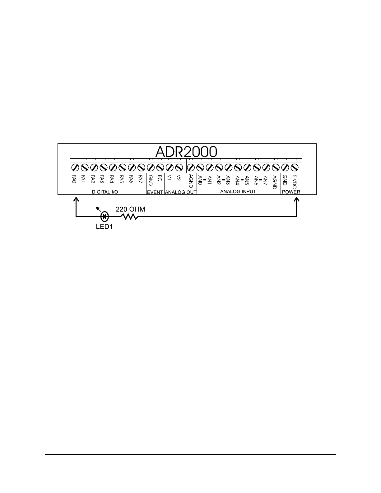
C) Connecting LED’s to Digital Ports
LED’s may be controlled using the digital I/O lines on the ADR2000. Only one additional
component is needed to drive LED’s. A current limit resistor is required for each LED with a value
of around 220 Ohms. The LED is the turned on by resetting PA0 to a logic zero or turned off by
setting PA0 to a logic one. The sample BASIC program demonstrates how to turn the LED on and
off.
10 OPEN “COM1:9600,N,8,1,CS,DS,RS” AS#1 ;opens com port
20 CLS ;clears screen
30 PRINT#1, “SETPA0" ;sets PA0*
40 REM ;forces <cr>
50 PRINT#1, “CPA11111110" ;configures PA0 as output
60 REM Turn on LED ;forces <cr>
70 PRINT#1, “RESPA0" ;turns on LED
80 REM Turn off LED ;forces <cr>
90 PRINT#1, “SETPA0" ;turns off LED
100 END
* PA0 remains in high impedance state until the CPA command is used to configure the port as
output.
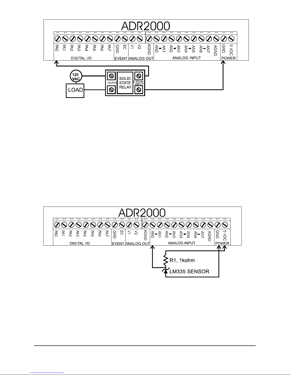
D) Driving Solid State Relays
Solid-State relays that require a DC voltage to operate may be driven by ADR2000 digital I/O lines
directly if the current input specification for the relay is 20mA or less. The relay must be rated for
the proper voltage and current required by the load. Each relay requires one digital I/O line to
operate and requires no other external components. The sample BASIC program demonstrates
how the relay is turned on. Note that the I/O line is RESET before the CPA command is used to
configure the port as output to avoid the relay turning on unexpectedly when the port is
configured.
ONTRAK CONTROL SYSTEMS INC. 18/23 www.ontrak.net
Page 20
10 OPEN “COM1:9600,N,8,1,CS,DS,RS” AS#1 ;opens com port
20 CLS ;clears screen
30 PRINT#1, “RESPA0" ;resets PA0
40 REM ;forces <cr>
50 PRINT#1, “CPA11111110" ;configures PA0 as output
60 REM Turn on relay ;forces <cr>
70 PRINT#1, “SETPA0" ;turns relay on
80 REM Turn off relay ;forces <cr>
90 PRINT#1, “RESPA0" ;turns relay off
E) Solid-State Temperature Measurement
The LM335 is a solid-state temperature sensor with an input span of -40 to +100C. It outputs
temperature 10mV per degree Kelvin. Only one external component is required to use the LM335
with the ADR2000. R1 is a 1Kohm resistor used to bias the LM335. The sample software program
reads the sensor using an RD0 command , converts the result to
Celsius and displays the temperature on the video screen.
10 OPEN”COM1:9600,N,8,1,CS,DS,RS” AS#1 ;open com port
20 CLS ;clear screen
30 LOCATE 1,1 ;locate cursor
40 PRINT#1, “RD0" ;send RD0 command to ADR2000
50 INPUT#1, READING ;retrieve data from ADR2000
60 TEMPERATURE=((READING/4095)*5)-2.73)*100 ;convert data to Celsius*
70 PRIN T “Temperature is”, TEM PERATURE ;display it
80 GOTO 30 ;repeat procedure
* voltage is converted to Celsius by subtracting 2.73 ( 273K ) and multiplying by 100.
ONTRAK CONTROL SYSTEMS INC. 19/23 www.ontrak.net
Page 21
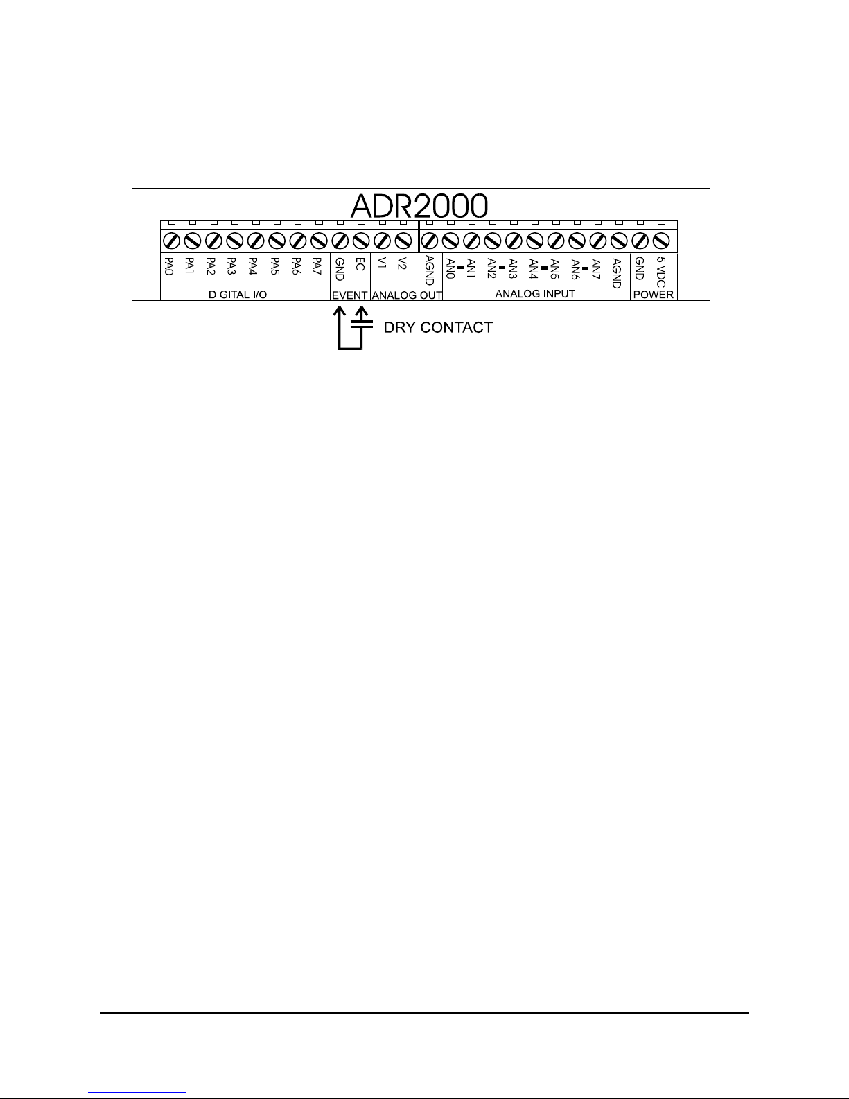
F) Event Counter Connections
The event counter accepts both TTL and dry contact inputs. TTL type inputs may be connected
directly to the EC input while dry contacts must be connected between GND and the EC input.
Events are counted on the rising edge of the input which is when the TTL signal switches from low
to high or the dry contact opens. The sample program rads the dry contact input and displays the
count result continuously on the video screen
10 OPEN”COM1:9600,N,8,1,CS,DS,RS” AS#1 ;open com port
20 CLS ;clear screen
30 LOCATE 1,1 ;locate cursor
40 PRINT#1, “CE" ;clears event counter
50 PRINT “PRESENT COUNT IS”,COUNT ;displays count data
60 PRINT#1, “RE” ;sends RE command to ADR2000
70 INPUT#1, COUNT ;retrieves count data
80 GOTO 50 ;repeat procedure
8. Calibration Procedures for the ADR2010
Internal Reference Adjustment
The ADR2010 internal reference must be set at 4.096V for maximum accuracy. R6 provides a +/-
1.5% adjustment range for the reference. This potentiometer is set at the factory and should not
be adjusted without the use of a precision voltmeter ( 6.5 digits or better ). To adjust the
reference, measure the reference voltage at TP1 and adjust R6 for a voltage of 4.0960 VDC.
ONTRAK CONTROL SYSTEMS INC. 20/23 www.ontrak.net
Page 22
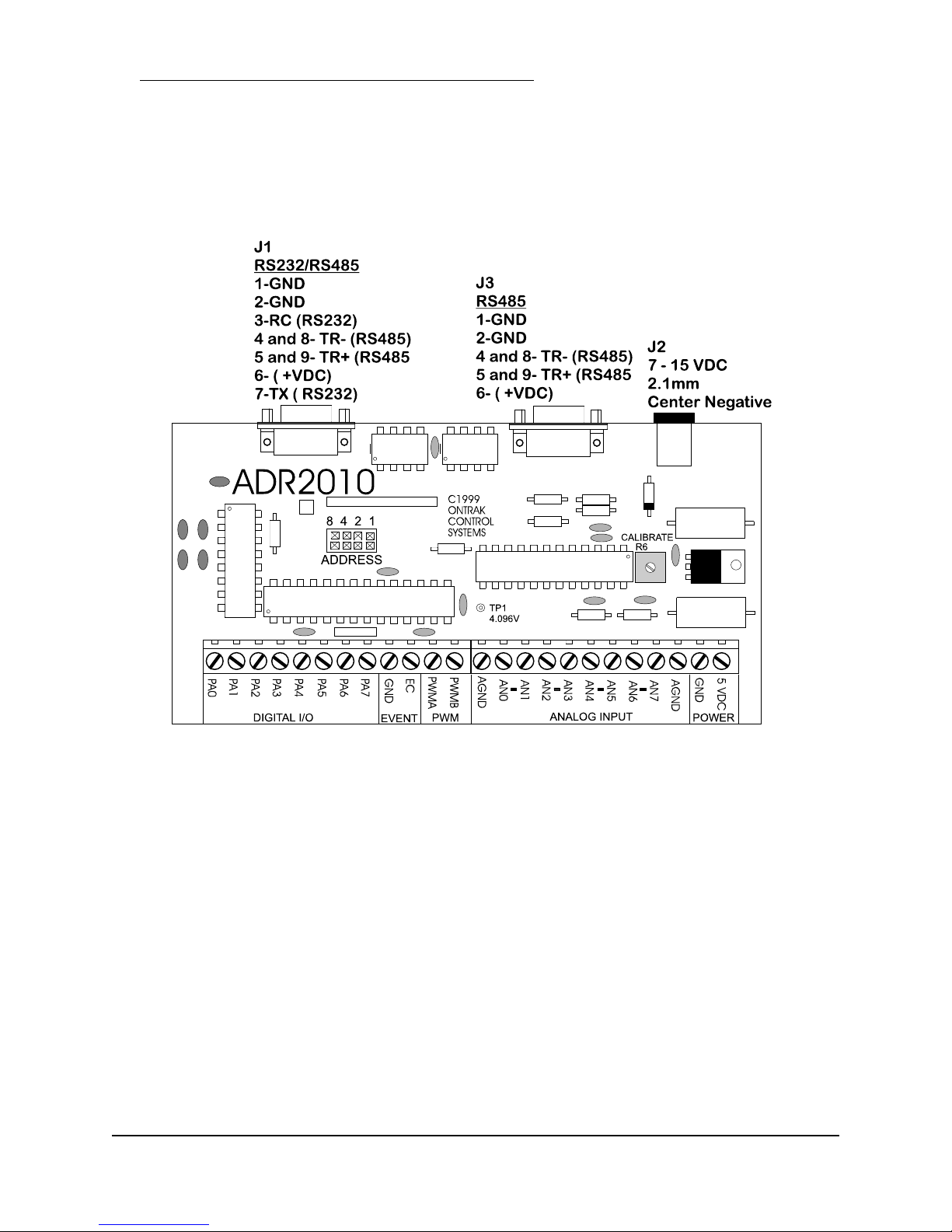
APPENDIX A CONNECTION DIAGRAM
ONTRAK CONTROL SYSTEMS INC. 21/23 www.ontrak.net
Page 23

APPENDIX B ELECTRICAL SPECIFICATIONS
ADR2010
Supply Voltage 5VDC+/- 10% or 7-9VDC via wall adaptor
Supply Current* 40mA Typical, 60mA Maximum
Operating Temperature 0-50C
* all digital outputs unloaded
Analog Inputs ( 8 )
Resolution 12 bits
Integral Nonlinearity 1 LSB MAX
Offset Error +/- 5LSB MAX
Accuracy 0.1% uncalibrated, ( .02% calibrated )
Range 0-5VDC.0-10VDC, +/- 5VDC, +/-10VDC
Protection OVP to +/- 15VDC
Input Impedance 10Kohm
PWM Outputs ( 2 )
Type PWM
Resolution 10 bits
Frequency 9.76Khz, 2.44Khz, 610Hz ( software selected)
Range TTL
Output Current Sink 20mA Maximum, Source 20mA Maximum
Digital I/O (8)
Sink Current 20mA Maximum
Source Current 20mA Maximum
Event Counter ( 1 )
Type TTL or Contact
Resolution 16 bits
Communication Interface
RS232 and RS485
9600 baud, 8 bit words, no parity, 1 start bit
Daisy-chain via RS485
Visit our web site at http://www.ontrak.net/ for additional applications and programming examples.
ONTRAK CONTROL SYSTEMS INC. 22/23 www.ontrak.net
Page 24
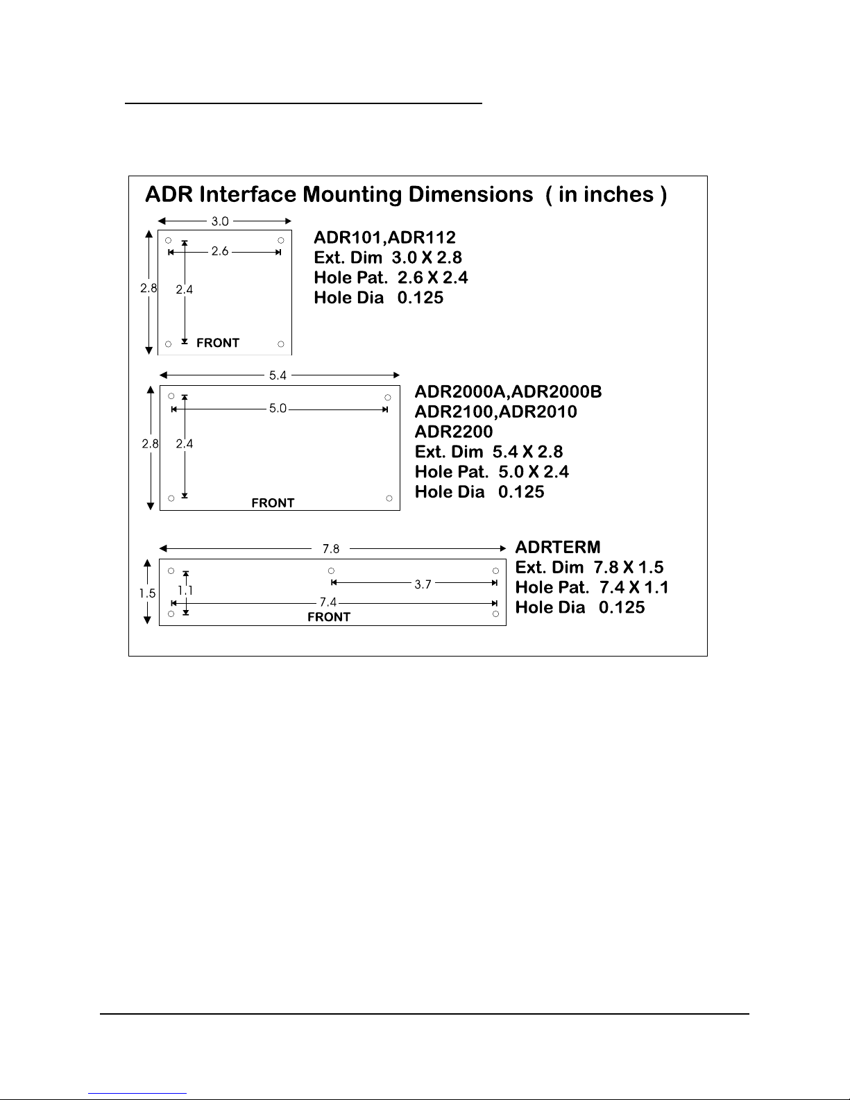
APPENDIX C MOUNTING DIMENSIONS
ONTRAK CONTROL SYSTEMS INC. 23/23 www.ontrak.net
 Loading...