

Page 1
OnTime Industrial Ethernet
100 Series
V 1.0
- 1 -
OnTime Industrial Networks
100 Series Installation Guide
Page 2
OnTime Industrial Ethernet
100 Series
V 1.0
- 2 -
Index
1. Introd uc tio n To OnTime Networks
1.1. History Of Ethernet
1.2. Industrial Ethernet Market
1.3. Switches vs. Hubs
1.3.1. Switch Operati on. MA C Address Learning
1.4. Twisted Pair Port S pecification
1.4.1. MDX/MDIX Technology , Crossed / S tr aight Cables
1.4.2. Auto-Negoti ation Protocol & Manual Configuration
1.5. Fibre Optic Port Specification
1.5.1. Fibre Optic Care
2. Switch Specifications
2.1. Power Supply Specific ation
2.2. Power Supply Connections
3. Technical Specification
3.1. Returns Procedure
3.2. Physical Specification
Page 3
OnTime Industrial Ethernet
100 Series
V 1.0
- 3 -
Section 1
Introd uc tio n t o OnTime
Company History
OnTime is dedicated to the implementation of industrial and deterministic Ethernet
infrastruct ure. OnTime Networks is a priv ately hel d company based in Norway and S weden.
We work closel y with a number of large aut omation compani es; enhancing older proprietary
networks and working in partnership developing new network technology.
Mission Statement
OnTime's mission is to provide an extension of Ethernet to the factory floor by offering
Ethernet products that fulfill industrial and real time requirements.
Core Tech nology
OnTime's Ethernet switches are based on a robust and reli able industrial design for m aximum
life cycle and minimum life time costs. Real time properties are implemented in order to
achieve determi nism for real time critical appli c ations.
Page 4
OnTime Industrial Ethernet
100 Series
V 1.0
- 4 -
Section 1.1
History of Ethernet
In late 1972, Metcalfe and his Xerox PARC colleagues developed the first experimental
Ethernet system to interconnect the Xerox Alto, a personal workstation with a graphi cal user
interface. The experimental Et hernet network was used to link Altos to each other, an d to
servers and laser printers.
The signal cl ock for the experiment al Ethernet interface was der ived from the Alt o's system
clock, which resulted in a data transmission rate on the ex perimental Ethernet of 2.94 Mbps.
Robert Metcalf e' s fir st ex per imental network was called the Alt o Aloha Network.
In 1973, Robert Metcalf e changed the name to "Ethernet," to make it clear that the system
could support any ty pe of computer; not just the Xerox Altos and to poi nt out that his ne w
network mechani sms had evolved well beyond the Aloha system. He chose to base the name
on the word "et her" as a way of describing an essent ial feature of the system: the physic al
medium (i.e., a cable) carries bits to all stations, m uc h the same way that the old "luminiferous
ether" was once thou ght to pr opagate el ectrom agnetic wav es through spac e. Thus, Et hernet
was born.”
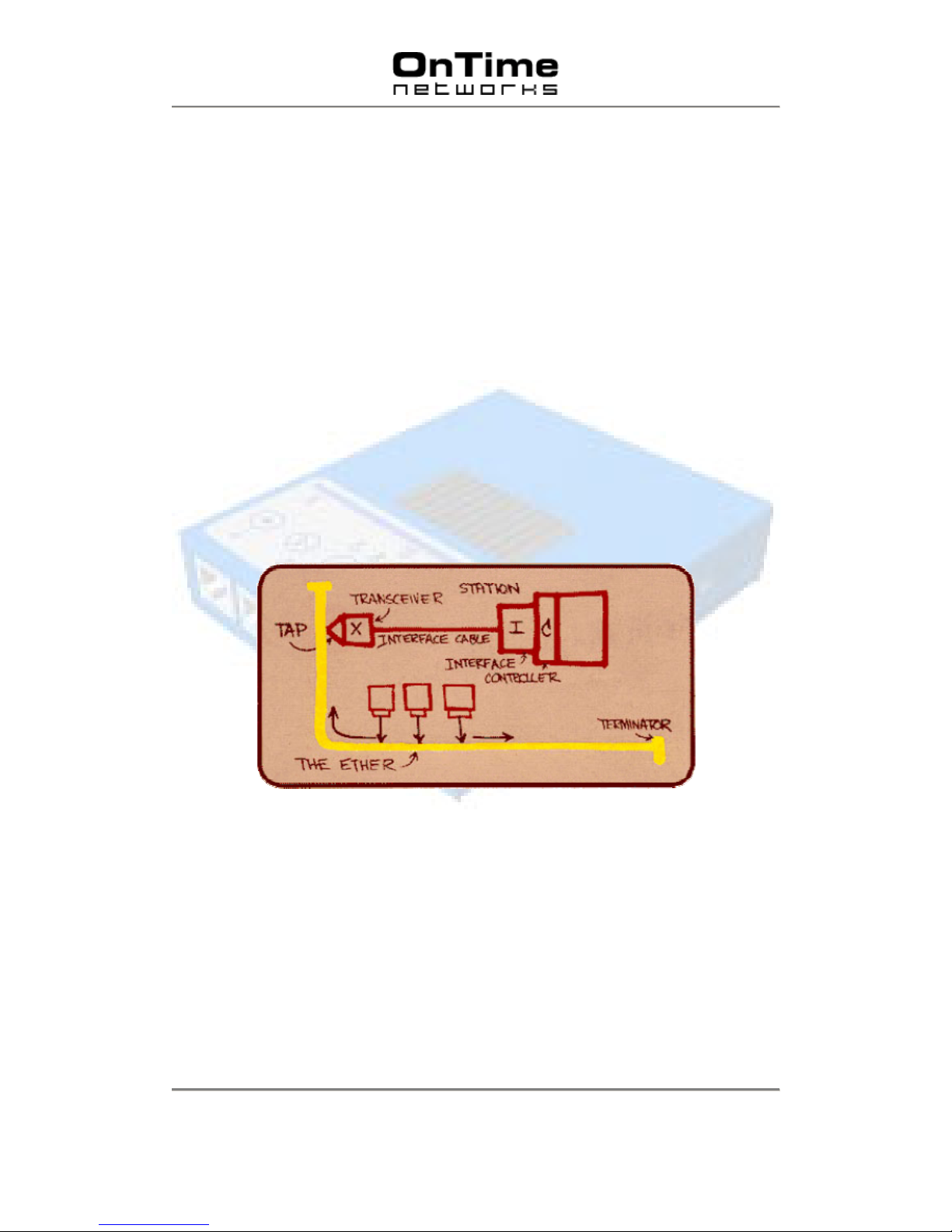
``The diagram ... was drawn by Dr. Robert M. Metcalfe in 1976 to present Ethernet ... to the
National Computer Confer ence in June of t hat y ear. O n the dr aw ing are the or iginal t erms for
describing Ethernet. Since then other terms have come into usage among Ethernet
enthusiasts.''
Page 5
OnTime Industrial Ethernet
100 Series
V 1.0
- 5 -
Section 1.2
Industrial Ethernet – What Are The Differences?
Within the UK Market, and possibly the majority of Europe, Ethernet is moving into the
Automation Industry. Manufacturers are exporting their legacy protocols onto Ethernet,
designing new IP based communication protocols and providing embedded Web-Pages
within PLCs to provide real-time information using simple tools like Internet Explorer and
Netscape.
However, the domain of Ethernet has always been controlled by the IT department who
configured office networks norm ally with an iron fist and di ctated to the company ho w the
network would be de signed with complex recover y prot ocol s li ke spanning t ree a nd SNM P to
help with f ault finding and system analy sis. If a network failure oc curred the IT department
would casually look at repairi ng the equipment - there was no real rush as it was an office
network. Howev er, with Industrial Ethernet you need very fast repai r time, and, with an IT
department not present on the factory floor the maintenance personnel need to be made
aware of the fault, find the error and repair it - quickly.
Industrial rated Switches are intended to be installed in harsh conditions and electrical
environments with the added benefit of fast recovery of a network failure. The On-Time
switches are an excellent ex ample of how such Switches should be de signed – v ery high
operating tem per atures, fast repair of redundant ring, layer 2 and layer 3 priorit y switching etc.
Without doubt, On-Time switches are technically superior to many similar models available on
the market.
Page 6
OnTime Industrial Ethernet
100 Series
V 1.0
- 6 -
Section 1.3
Switches vs. Hubs
A hub consists of a number of port s normall y with either RJ-45 (c opper) socket s and / or fi bre
optic ports that hav e a num ber of dif ferent styles of fibre optic sockets. Usually a ‘patch cable’
is connected to the hub; the other end is normally connected to a device (PC, Printer etc).
Note: It should be noted that when a hub requires an ‘up-link’ connection to a further
hub a cross-over style cabl e is req uired.
A hub has no intell igence and therefore is unable to identify addresses or any inf ormation
contained withi n the Header frame of an Ether net packet. T his means that it i s not capabl e of
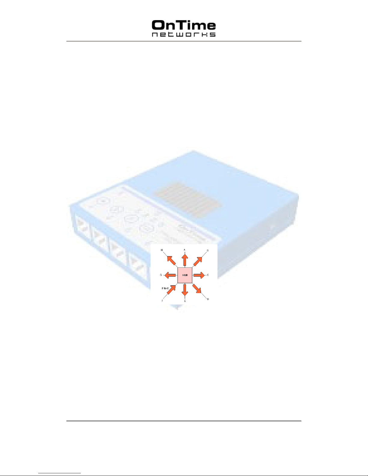
determining which por t to send the frame to. Therefore, every frame is sent to every port.
Note: Industrial hubs can only connect to equipment that operates at the same speed.
A network of repeaters and hub s is called a ‘Shared Ethernet ’ or ‘Collision Domai n’. Various
systems will all compete with each other using ‘Carrier Sense Multiple Access / Collision
Detect’ (CSMA/CD) pr otocol. This means that only one system is allowed to proceed with
a transmission of a frame within a Collision Domain at any one time. This is a major
disadvantage when using Hubs and Repeaters within a network.
If a hub sees a collision on a cable segment, it is detected and a ‘jam’ signal is generated.
The ‘jam’ signal is sent to all connected devi ces. This ensures that ev ery device is aware of
the collision and t hey do not attem pt to transmit during the collision.
All Ports Receive the Sam e Ether net Frame
To summarise, hubs operate wit h the following limitations:
• Only a single speed of operati on – no ability to automati cally c hange between 10M or
100M.
• Only one system is allowed to proceed with a transmission of a frame within a
Collision Domain at any one time.
• Hubs require special ‘cros sed’ cabl es to enabl es l ink s fr om Hub to Hub. (I f no up-l i nk
port is present)
Page 7
OnTime Industrial Ethernet
100 Series
V 1.0
- 7 -
Section 1.3. 1
Switch Ope r a tion
Introduction
A switch has to forward and receive packets from one LAN or device to another. The switch
could forward all pac k ets, but if this was the case it would have similar behavior to a hub.
It would be more intelligent if the switch only forwarded packets which need to travel from one
LAN or device to another. To do t his, the switch must learn which devices or LANs are
connected to each port. In simplistic terms; it needs to learn the desti nation and source ports
of each and every packet rec eiv ed on eac h individual Switch port. Once lear nt, any identically
addressed packet will be automatically be forwarded.
Error Detection
The switch stores ev ery incoming pack et and scans this for err ors, usually by checking the
frame CRC (cyclic redundancy check sum). If any errors are found or det ected the packet i s
discarded. In addition each frame is checked for size. Undersized packets (less than 64
Bytes) and oversi z ed pac k ets (mor e than 1518 bytes)* are also discarded.
Once these basic checks have been carried out the switch can then start learning packet
source and destination information.
Note: When implementing Packet Priority this increases to 1522 o r 1536 Byt es.
Flooding
The switch needs to make a decision regarding which port(s) the packet is to be forwarded to.
This decision is based upon t he MAC tables that are maint ained and updated automatic ally
by the Switch. The process is kno wn as Layer 2 Switc hing.
When first powered on the MAC tables within the Switch are empty. When a packet is
received on a port the S witch doe s not kno w where th e desti nation MA C address is l ocated.
The Switch learns the address by ‘flooding’ the packet out to all ports. Eventually, the
destination node r esponds, the address i s located and the S witch remembers the desti nation
port. In simpli stic terms; when a Switch receiv es a packet on a port it stores the source M AC
address in the MAC table that corresponds to that Port. The flooding technique is always
used with Broadcast and Multicast packets. If the switch is equipped with multicast
management then multi c ast pac k ets will not be flooded.
Page 8
OnTime Industrial Ethernet
100 Series
V 1.0
- 8 -
Section 1.3. 1
Switch Ope r a ti on (Cont..)
MAC Table
A MAC table c an hold up t o 8000 entr ies; and wit h a tot al packet memory of ov er 1MB thi s is
adequate for nor mal networks. Natural ly, devic es will be disconnected f rom Ports duri ng the
life of a net work. If t he MAC tabl e did not aut omati cally monit or for i dle nodes the t able would
become full. If a node has been idl e for mor e than a few seconds the source and de stinati on
informati on for that node will be del eted f rom t he table. Thi s is comm only known as the ‘age
time’. To reset the table power cycle the Switch.MAC table size is normally always large
enough for industrial networks. Packet memory size on the other hand can affect performance
and ability to handl e short high load/ov erload situati ons when an event occurs in a control
network or similar industrial network.
Page 9
OnTime Industrial Ethernet
100 Series
V 1.0
- 9 -
Section 1.3. 1
Switch Ope r a ti on (Cont..)
Full Wire Speed
The Switch supports f ull wire speed. This equates to 100Mbi t/s full duplex on ev ery port. In
detail 100Mbit/s in each direction on all ports equals 200Mbit/ s per por t.
Page 10
OnTime Industrial Ethernet
100 Series
V 1.0
- 10 -
Section 1.4
Twisted Pair Port Specification
Introduction
The 200 Series Switc h is available with up to eight copper ports. The copper ports support the
long cable specifi cation t hat enables standard CAT 5e copper c ables to run up to 150 M eter s
when used with dev ices that also support t his specificati on. This highlights the enhanced
design specifi cat ion th e swi t ch emp lo ys when used in noisy electrical environmen t s.
In industrial networks long cables should be avoided but equipment specified
according to long cable sp ecification gives more margins for disturbances.
MDX/MDIX
There are two types of copper Ethernet por ts available; MDI (Medium Dependant Interface)
and MDIX (Medi um Dependant I nterf ace Cr ossov er). The MDI port ty pes are a ssociat ed wit h
copper interf aces available on NICs (Network Int erface Cards), PLCs, VSDs and DCSs etc.
The latter type of interface (MDIX) is found on Hubs or Switches.
In addition t her e ar e two types of Ether net cable available. These are referred to as a ‘straight
through cable’ or ‘c r ossed cable’.
STRAIGHT CONNECTION –Switch-PLC, Hub-PLC, Switch-NIC etc.
Connector A Connector B
Pair 1 pin 4 <-------> Pin 4
pin 5 <-------> Pin 5
Pair 2 TD + pin 3 <-------> Pin 3 TD +
TD - pin 6 <-------> Pin 6 TD -
Pair 3 RD + pin 1 <-------> Pin 1 RD +
RD - pin 2 <-------> Pin 2 RD -
Pair 4 pin 7 <-------> Pin 7
pin 8 <-------> Pin 8
CROSSED CONNECTION – Switch-Switch, Hub-Hub, Switch-Hub etc.
Connector A Connector B
Pair 1 pin 4 <-------> Pin 7
pin 5 <-------> Pin 8
Pair 2 TD + pin 3 <-------> Pin 1 RD +
TD - pin 6 <-------> Pin 2 RD -
Pair 3 RD + pin 1 <-------> Pin 3 TD +
RD - pin 2 <-------> Pin 6 TD -
Pair 4 pin 7 <-------> Pin 4
pin 8 <-------> Pin 5
Page 11
OnTime Industrial Ethernet
100 Series
V 1.0
- 11 -
Section 1.4 (Cont)
Twisted Pair Port Specification
Auto MDX/MDIX
The complete range of OnTime Switches automatically detects the transmit and receive
copper pairs used in a pat ch cabl e. This elimi nates the need t o source the two types of patch
cable (crossed and straight through) highlighted above and therefore reduces the cost of
carrying two types of spares. T hi s feature cannot be deactivated.
Electrical Isolation
The copper (TX) port s incorporate high electrical isolati on between the signal lines and the
internal electr onics. In addi tion, the switch can al so withstand over 500 A mps through the
shield for short per iods of time (20-30m S) without eff ecting the operati on and communicati on
of the Switch. However, this is not advisable. Fibre optical cabl es should be used in such
environments. E ac h TX port is isolated to chassis and other por ts. Isolation is rated 1500V rms
(1 minute).
Auto-Negotiation
Auto-Negoti ation is a protocol that controls the speed and duplex of a copper cable when a
connection is established between two Ether net devices. Auto-Negotiation detects the various
modes that ex i st in t he devi ce on t he other end of t he cabl e and hi ghli ght s it s own abi liti es to
automatically configure itself. Therefore, it will automatically operate at the highest
performanc e in r elati on t o speed and duplex . This al lows sim pl e and aut om atic c onnecti on of
devices that support a variety of m odes from a variet y of manufactur er s. The auto-negotiation
protocol only functions on copper ports.
As standard the range of OnTime Switches are shipped with the Auto-Negotiation feature
enabled. However, if required a manual configuration process is possible using the
push buttons. These are lo cat ed on the f ron t p anel of the Switch.
Page 12
OnTime Industrial Ethernet
100 Series
V 1.0
- 12 -
Section 1.4 (Cont)
Twisted Pair Port Specification
Manual Configuration
The front panel LEDs provides indication on the Status of eac h port. In addition, each port can
be manually c onfigured for speed, duplex and auto-negotiati on using the push button panel
located on the front of the Switch.
Normal Indication Mode
When the unit is first powered on the Swit ch front panel will operate in normal m ode. In this
condition the por t LED will indicate link and traffic stat us.
Select Port Mode
The front panel will enter Selec t Port Mode when the Sel ect Port button i s pressed. Pressing
the Select Port button once will illuminate Port 1 LED – manual control of this port is now
available. Pressing the Sel ect Port button a second ti me will illumi nate Port 2 LED – manual
control of this port is now available. Each additional port can be placed i nto Manual mode by
subsequent pressing of the Select Port button.
If no buttons are pressed f or 30 seconds the unit will return to Normal Mode.
Speed Button
Pressing the Speed Butt on once selects 10M, twic e enables 100M and three enables aut onegotiation mode.
Duplex Button
Pressing the Duplex Button changes the Port dupl ex mode from full dupl ex to half duplex or
vice versa.
Save Button
Newly configured settings are stored in non-volatile memory when the Save Button is
pressed.
Note: Manual configuration of fibre ports is not possible.
Page 13
OnTime Industrial Ethernet
100 Series
V 1.0
- 13 -
Section 1.5
Fibre Optic Port Specification
Fibre Optic Communications
The fibre optic (FX) ports are available with either multi-mode or single mode fibre
transceivers. Multi-mode transceivers are av ailable with MT RJ, SC or ST style connectors.
Single mode transceivers are only available with LC style connectors.
Transceiver Type Light Wavelength Fibre Diameter Maximum Distance
Multi Mode 2KM
1300 nM 50/125 uM or
62.5/125uM
3 KM
Single Mode 15KM
1300 nM 9/125 uM 15 KM
Note: The fibre di stanc e specif ied must take into account loss budgets as detailed below.
Page 14
OnTime Industrial Ethernet
100 Series
V 1.0
- 14 -
Section 1.5
Fibre Optic Port Specification (Cont..)
Fibre Optic Power Budgets
Single Mode Transceiver
SINGLE MODE
(xx/125)
MTRJ
15km[dBm]
Max. Receive Power -8
Min. Receive Power -31
Max. Optical Power -14
Min. Optical Power -20
Multi Mode Transceiver
MULTI MODE
(50/125)
MTRJ
[dBm]
Max. Receive Power -14
Min. Receive Power -31
Max. Optical Power -14
Min. Optical Power -23,4
MULTI MODE
(62.5/125)
MTRJ
[dBm]
Max. Receive Power -14
Min. Receive Power -31
Max. Optical Power -14
Min. Optical Power -20
Note: Fibre Ports are always configured for 100 Mbit/s and full duplex.
Page 15

OnTime Industrial Ethernet
100 Series
V 1.0
- 15 -
Section 1.5. 1
Fibre Optic Port Specification (Cont..)
Fibre Optic Care
Fibre optic tr ansmission medium is usually made of Glass. In addition, the diameter of the
fibre can be as low as 9um. In compari son, the diameter of an average piece of Human hair is
40 um.
Therefore, a small piece of dust or contaminate located on the end of a patch cable
could easily disrupt communications.
The fibre optic transceivers and associated patch cables must be treated with great care.
Therefore, t he f ollowing rul es shoul d be adher ed t o d ur ing any comm issioni ng work and f i br e
optic installation.
• Dust caps must be replaced immediately after removal of patch cable from
transceiv er or patch box. Failur e to comply c ould result i n damage to t ransceiver s or
patch cables.
• Keep hands clean when touchi ng fibre optic cable.
• Patch cables should be cleaned with IPA and dried with a lint-free cloth before
installation.
• Once patch cables hav e been installed dust will not ingress the transceiver
NOTE: Permanent damage to both fibre patch cords and fiber optic transceiver
components may be the result of just a small in visible piece of dust!
Page 16
OnTime Industrial Ethernet
100 Series
V 1.0
- 16 -
Section 2.0
Switch Specifications
Power Su pp ly Co n ne c t or
The switch is designed to operat e permanent ly over a ver y wide range of power (19 V DC to
72 V DC). Two redundant inputs are provided to provide enhanced redundancy if either
supply fails.
The power supply dr aws po wer from t he input t hat has the hi ghest potenti al dif fer ence when
compared to the alt er nate supply.
This enables use of a 48V source as primar y supply with a 24VDC battery as back up.
Power supply inputs have reverse polarity protection.
Page 17
OnTime Industrial Ethernet
100 Series
V 1.0
- 17 -
Section 3.0
Switch Technical Specification
Interface Specif ications
RJ-45 Ports 10/100 BaseT(x)
Auto Negotiation Feature
Speed
Full and Half Duplex m ode
Auto MDI/MDI-X
Manual Negoti ation
Speed
Full and Half Duplex m ode
Fibre Ports 100BaseFX Ports
Fibre Specificat io ns
Distances Multi mode 2-3KM
Single mode 15KM
Wavelength 1300nM
Power Specification
Input Voltage 19VDC..72VDC
Input Current (@24V DC) Typical 3 Watts
Inrush Current Not Greater Than Input Current.
Maximum Current
Maximum 5Watts
(Model Dependant)
Page 18
OnTime Industrial Ethernet
100 Series
V 1.0
- 18 -
Section 5.0
Switch Technical Specification
Environment al Speci f ication
Indoor use or corresponding environment
Altitude up to 2000M
Operating temper ature (-40 .. +70°C)
Humidity 5-95’C RHD Non Condensi ng
Enclosure IP40
Climatic
Cold IEC 68-2-1 Ad (-25 ‘C operati onal 16 Hour s)
Storage IE C 68- 2- 1 A d (-40 ’C 16 Hour s)
Dry Heat IE C 68- 2-2 Bd (+70 ’C operational 16 Hours)
Humidity IEC 68- 2- 30 Db ( 25 ‘C .. 55 ‘C 95% 6 Cycles 24 Hours)
Mechanical
Oscillation IEC 255-21-1 Class 1
Shock IEC 255-21-2 Class 1
Enclosures IEC 529, IP 40
Electromagnetic Compatibility (EMC)
Industrial Immunity EN 61000-6-2
Industrial Emission EN 50081-2
Home / Office Emission EN 50081-1
Radiated Immunity
ESD EN 61000-4-2 (4/8 kV)
Magnetic Field EN 61000-4-8 (30A/m)
RF Field Disturbance EN 61000-4-3
10 V/m 80% AM
80 .. 1000MHz
Page 19

OnTime Industrial Ethernet
100 Series
V 1.0
- 19 -
Section 5.0
Switch Technical Specification
Test Standards
Conducted Immunity
Fast Transients EN 6100-4-4
AC/DC 2kV, Signal 1kV
Surge Immunity EN 6100-4-5
AC: 2kV/1kV
DC: 0.5kV/0.5kV
Signal 1kV/-
Voltage Dips
Voltage Interrupti ons EN 6100-4-11 for AC Supply
Conduced RF
Disturbance EN 6100-4-6
10V, 80% AM, 0, 15-80 MHz
Radiated Immunity
ESD EN 61000-4-2 (4/8 kV)
Magnetic Field EN 61000-4-8 (30A/m)
RF Field Disturbance EN 61000-4-3
10 V/m 80% AM
80 .. 1000MHz
Safety
Low Voltage
Directive Standard EN 60950
Class 1 equipment, in which exposed conductive parts are bonded to a connec ting
means for a protectiv e c onduc tor.
Eye Safety IEC 825-1 Class 1
Page 20
OnTime Industrial Ethernet
100 Series
V 1.0
- 20 -
Section 5.1
Switch Technical Specification
Returns Procedu re
Contact your equipment supplier before returning any equipment.
Equipment will not be accept ed wi thout an allocated returns number.
Page 21
OnTime Industrial Ethernet
100 Series
V 1.0
- 21 -
Section 5.2
Physical Specification
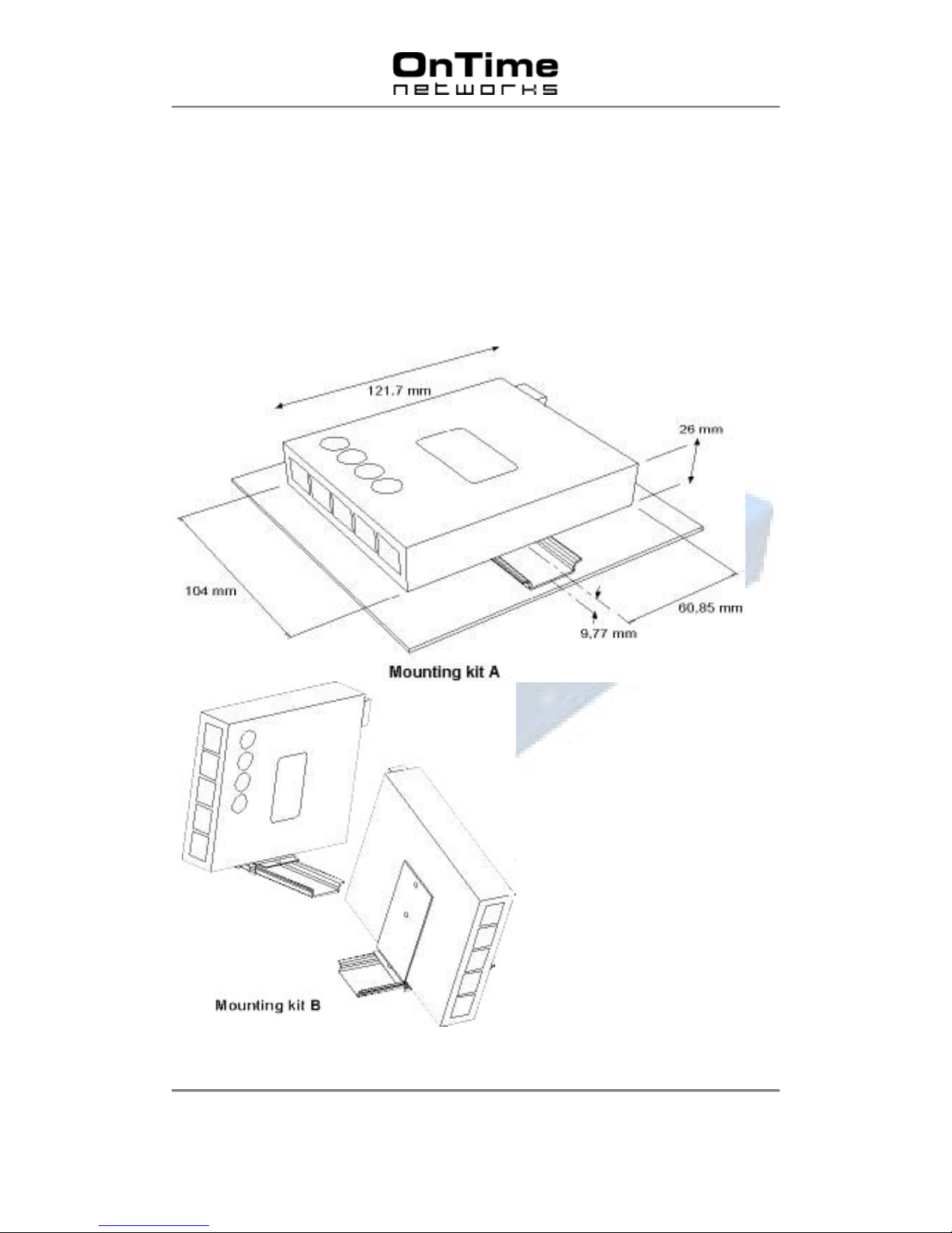
In addition to the f our rubber feet for desktop instal lation, two DIN Rail mounti ng options are
available. Usi ng the supplied screws the DIN c lip can be attached to the bottom base plate of
the switch. An additional mounting accessory is available for vertical DIN rail mounti ng.
Note that if the DIN clip is not mounted the switch will not fulfill ingress IP40 pr otection.
 Loading...