

Ontech GSM Mini 9009, GSM Relay 9010 User Manual
Ontech GSM Mini 9009
Ontech GSM Relay 9010
User Manual

Welcome
Thank you for choosing Ontech GSM Mini 9009.
We hope that the product will satisfy your needs and that you will find this manual
easy to handle and that it guides you in an appropriate way.
If you want to learn more, please visit our web site at www.ondico.se
can find more information.
Questions can be directed to support@ondico.se.
In this manual the Ontech GSM Mini 9009 will sometimes be called master unit and
Ontech GSM Relay 9010 will be called slave unit.
SMS text will be shown with gray background and and bold text, for example:
1234#1*0#
Also the buttons to be pressed when using a telephone in tone mode (not pulse) is
shown in this way.
Text in italic indicates a menu in your mobile phone, for example;
Contacts
, where you
Important!
Not intended for direct plug-in equipment, only for plugs with a cord.
-2-

Content
Welcome .......................................................................................................................... 2
Ontech GSM Mini 9009 ................................................................................................. 5
Overview.................................................................................................................................................................5
Content in package .........................................................................................................................................6
Get started.............................................................................................................................................................6
Remote relay........................................................................................................................................................8
Operate the relay manually................................................................................................................... 8
Operate the relay by calling it up......................................................................................................8
Operate the relay with SMS ..................................................................................................................9
Alarm...................................................................................................................................................................... 10
Connect an alarm detector................................................................................................................ 10
Change operation mode between NO and NC.................................................................... 10
Alarmrelay..................................................................................................................................................... 12
Turn on/off the alarm function........................................................................................................ 12
Turn off the alarm function by calling up .................................................................................12
Turn off the alarm function with SMS.......................................................................................... 12
When an alarm is activated................................................................................................................ 13
Interpreting the SMS.............................................................................................................................. 13
Acknowledge an alarm......................................................................................................................... 13
Temperature guard.......................................................................................................................................14
Temperature...................................................................................................................................................... 14
Status-SMS.......................................................................................................................................................... 15
Power the unit with battery .................................................................................................................... 16
Functions............................................................................................................................................................. 16
Commands................................................................................................................................................... 16
Push button................................................................................................................................................. 17
The lamps of the unit............................................................................................................................. 17
Ontech GSM Relay 9010 .............................................................................................19
Overview.............................................................................................................................................................. 19
Content of the package.............................................................................................................................19
Get started.......................................................................................................................................................... 20
The identity of the unit ......................................................................................................................... 20
Setting the radio channel....................................................................................................................21
Remote relay..................................................................................................................................................... 23
Operate the relay manually................................................................................................................ 23
Operate the relay by calling it up................................................................................................... 23
Operate the relay with SMS ............................................................................................................... 24
Alarm function................................................................................................................................................. 25
-3-

Connect an alarm detector................................................................................................................ 25
Change operation mode between NO and NC.................................................................... 25
Turn on/off the alarm function........................................................................................................ 27
When an alarm is activated................................................................................................................ 27
Acknowledge an alarm......................................................................................................................... 27
Functions............................................................................................................................................................. 29
Push button................................................................................................................................................. 29
The lamp of the unit............................................................................................................................... 29
Trubble shooting............................................................................................................................................ 30
Tip!........................................................................................................................................................................... 31
Ontech GSM Mini 9009......................................................................................................................... 32
Ontech GSM Relay 9010....................................................................................................................... 32
Declaration of comformity....................................................................................................................... 33
-4-

Ontech GSM Mini 9009
Overview
Ontech GSM Mini 9009 has a built-in power relay 230V/16A which can be operated
with SMS or by an ordinary telephone call. The unit also has two alarm inputs which
both can be set to operate in either Normally Open-mode or Normally Closed-mode.
When the alarm input is activated an SMS will be sent to up to ten different mobile
phone numbers.
The unit has a temperature guard that sends an alarm message if the temperature
drops below 5 degrees Celsius. The unit also reports the actual temperature.
Ontech GSM Relay 9010 is a slave unit that communicates with Ontech GSM Mini
9009 with a short range radio. The unit has a built-in power relay 230V/16A and two
alarm inputs. Up to seven Ontech GSM Relay 9010 can be connected and
individually operated by each Ontech GSM Mini 9009 . The operating range is
approx. 30 meters, but each slave unit also works as a repeater in order to increase
the operating range.
-5-

Content in package
• Ontech GSM Mini 9009
• Antenna
• Users Manual
• Connection cable
Get started
In order to use the unit you must have an SIM-card for a mobile telephone and
access to a mobile phone.
1. Insert the SIM-card in a GSM mobile phone.
2. Deactivate the PIN-code function. See the user manual of the mobile
phone..
3. Choose Contacts in the mobile phones menu.
Be sure you are saving the settings in the memory of the SIM-card
and not in the memory of the telephone.
a. Create a new entry, name it ”PINCODE”
b. In the field for telephone number, enter your personal four digit
number. This number is the PINCODE you must enter each time
you contact the unit..
4. Create a send list for alarm
a. Create a new contact. Name it ”SMS0” (note that 0 is zero and not
the letter O).
b. Enter the mobile phone number for the receiver of the SMS. Save.
c. The following records in the send-list is named SMS1, SMS2 etc,
and the mobile numbers are entered. All numbers from SMS0 to
SMS9 can be used.
5. If you wish to activate the temperature guard (see page 14.)
a. Create a new contact. Name it ”TEMP”. No phone number has to
be entered but if the phone requires it, any number can be
entered.
6. If you wish to activate ALARMRELAY (see page 12.)
-6-
a. Create a new contact. Name it ”ALARMRELAY”. No phone number
has to be entered but if the phone requires it, any number can be
entered.
7. Turn off the mobile phone and remove the SIM-card.
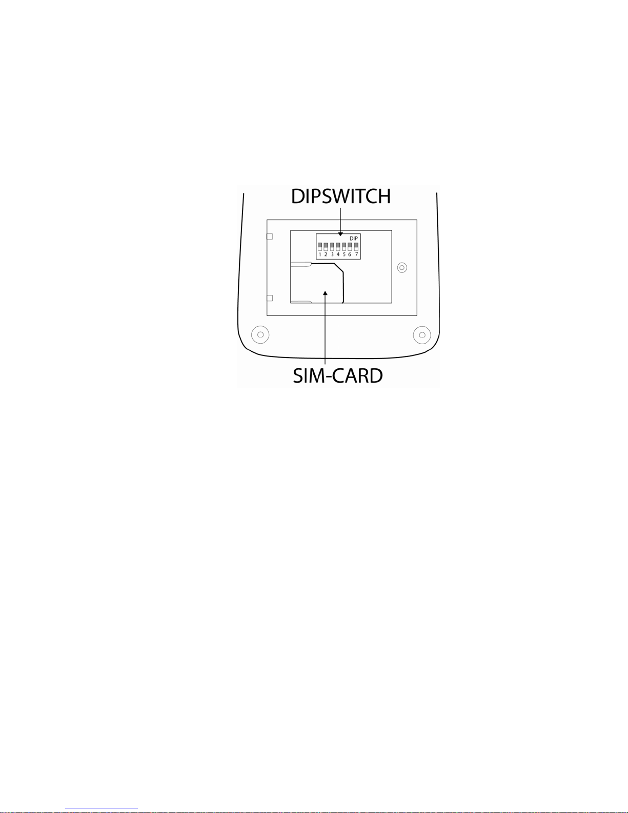
8. Remove the cover door on back of the unit. Use a small screwdriver.
9. Insert the SIM-card in the holder (see below). Replace the cover door.
10. Connect the antenna to the unit
11. Insert the unit in a power jack. The following happens:
a. The green lamp starts flashing for about 45 seconds. This
indicates that the unit is searching an GSM network.
b. Finally the green lamp is lit. The unit is communicating with the
GSM network and the unit is ready for use.
c. If both the red and the green lamp is flashing, this indicates:
i. SIM-kort is missing
ii. The PIN-code on the SIM-card is not deactivated. See
item 2.
-7-

Remote relay
With this function you can call up or send SMS to the unit and operate the
230V/16A relay.
Insert the unit in the wall power socket you wish. Put the power contact of the
device you want to operate in the power socket of the unit.
Operate the relay manually
You can make the relay switch by pressing the button on the unit. When the relay is
on, the red lamp is lit and when the relay is off, the red lamp is not lit.
Operate the relay by calling it up
1. Call up the unit. Be sure you use tone mode on the telephone.
2. The unit answers with a beep.
3. Press your PIN-code and then #.
Example: 1234#
If the PIN-code is correct the unit replies with a beep. If it is not correct the
call is disconnected. Call again and try.
4. Turn on the relay by pressing the following buttons:
1*1#
The unit replies with a beep. Hang up the receiver. If the unit replies with
two beeps, try again.
5. Turn off the relay by pressing the following buttons:
0*1#
The unit replies with a beep. Hang up the receiver. If the unit replies with
two beeps, try again.
6. Turn on the relay with timer function
The relay can be turned on and you can set the number of hours you want
it to be active before it switches off (between 1 and 99 h). Press the
following buttons:
1*1*T# (T= the number of hours you want the relay to be in on mode).
The unit replies with a beep. Hang up the receiver. If the unit replies with
two beeps, try again.
-8-

After you finished one operation you can directly execute next operation without
hanging up the receiver. When you have executed all operation, hang up.
Operate the relay with SMS
1. Turn on the relay, send an SMS with the following message:
ABCD#1*1# (where ABCD is your PIN-code)
2. Turn off the relay, send an SMS with the following message:
ABCD#0*1# (where ABCD is your PIN-code)
3. Turn on the relay with timer function
The relay can be turned on and you can set the number of hours you want
it on before it switches to off. (between 1 and 99 h). Send the following
message:
ABCD #1*1*T# (where ABCD is your PIN-code, T= the number of hours
you want the relay to be in on mode).
Tip!
Instead of writing the symbol * you can use all letters on button 7 (p, q, r or s)
Instead of writing the symbol # you can use all letters on button 9 (w, x, y or z)
Tip!
If you not are sure about the settings of the unit, you can request a status-SMS. See
page15.
-9-
Alarm
The unit has two alarm inputs. The y can be set to operate in Normally Open –mode
(NO) or Normally Closed-mode (NC).
Connect an alarm detector
An alarm detector is a device that connects or disconnects a circuit when it is
activated. Example of such devices are PIR units, magnetic detectors, level guards or
similar.
On the bottom you will find a jacket with four connectors.
They are marked as follows:
G Ground
A Alarm A
B Alarm B
12V Voltage 12 V (not for powering external devices)
The connection cable has a connector in one end that fits in the jacket.
Change operation mode between NO and NC
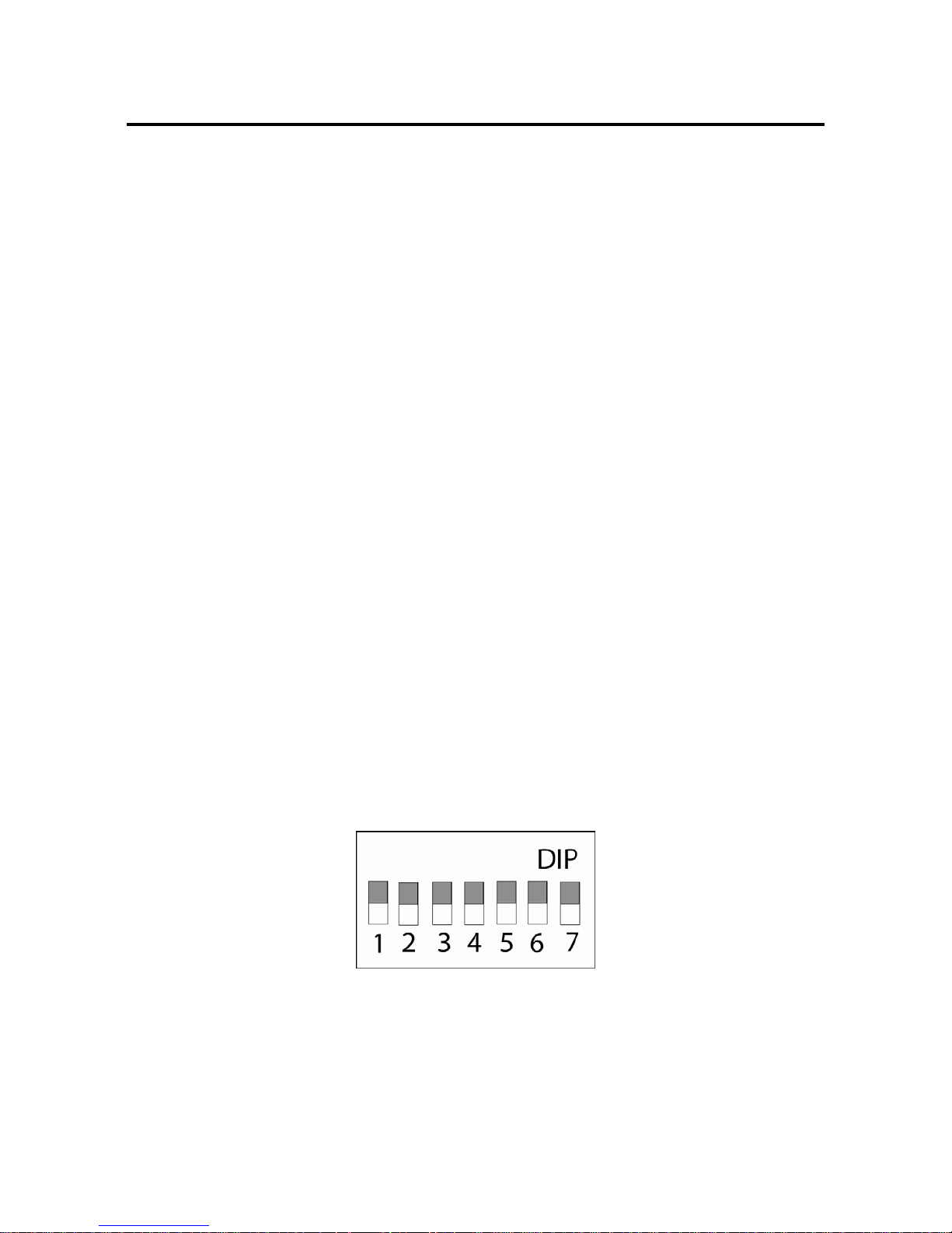
Under the back cover door you will find a DIP-switch with 7 switches. They are
numbered from 1-7.
Factory setting for switch no 1 is OFF. This means that the alarm inputs are set to
NO mode. The unit sends ALARM A if connector 2 and 4 is connected and sends
ALARM B if connector 3 and 4 is connected.
If switch no 1 is set to ON the NC mode is activated. The unit sends ALARM A if the
connection between connector 2 and 4 is disconnected and sends ALARM B if the
connection between connector 3 and 4 is disconnected.
-10-
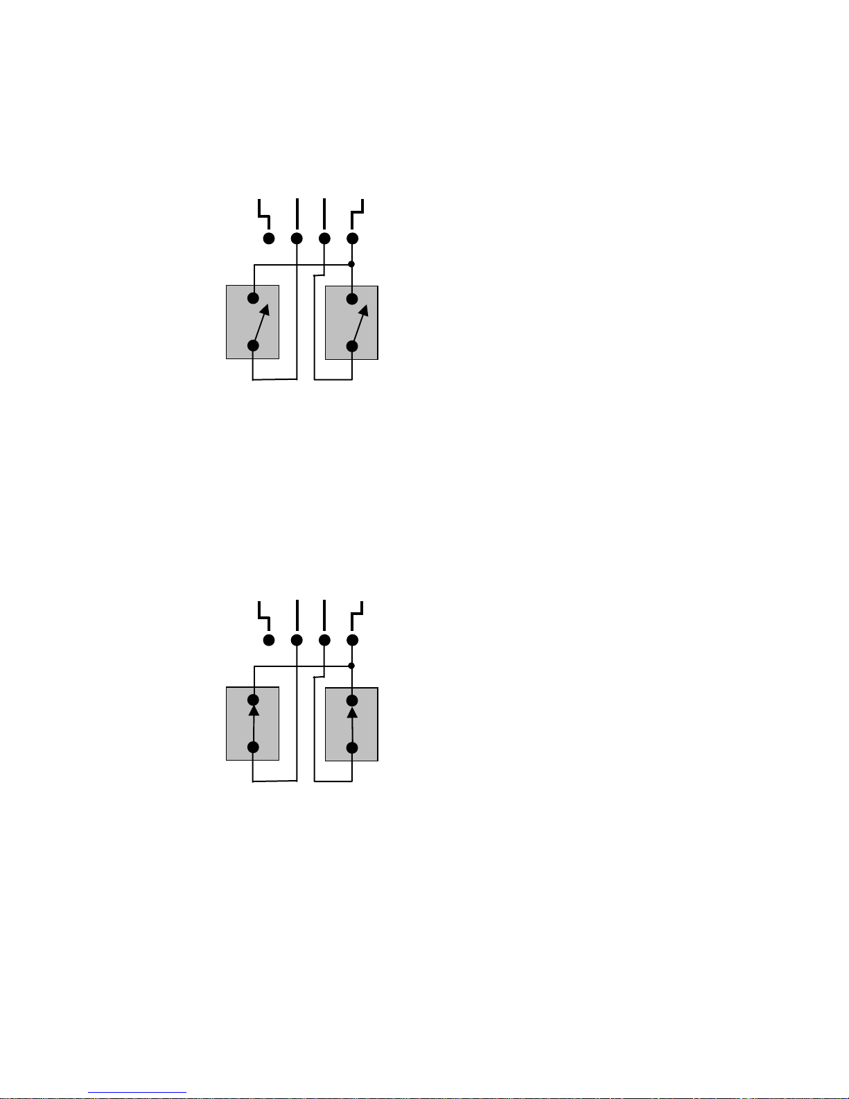
Suggestion for connection of alarm detector NO mode
G B 12V A
Sensor B Sensor A
Suggestion for connection of alarm detector NC mode
G B 12V A
Sensor B Sensor A
-11-
 Loading...