

Page 1
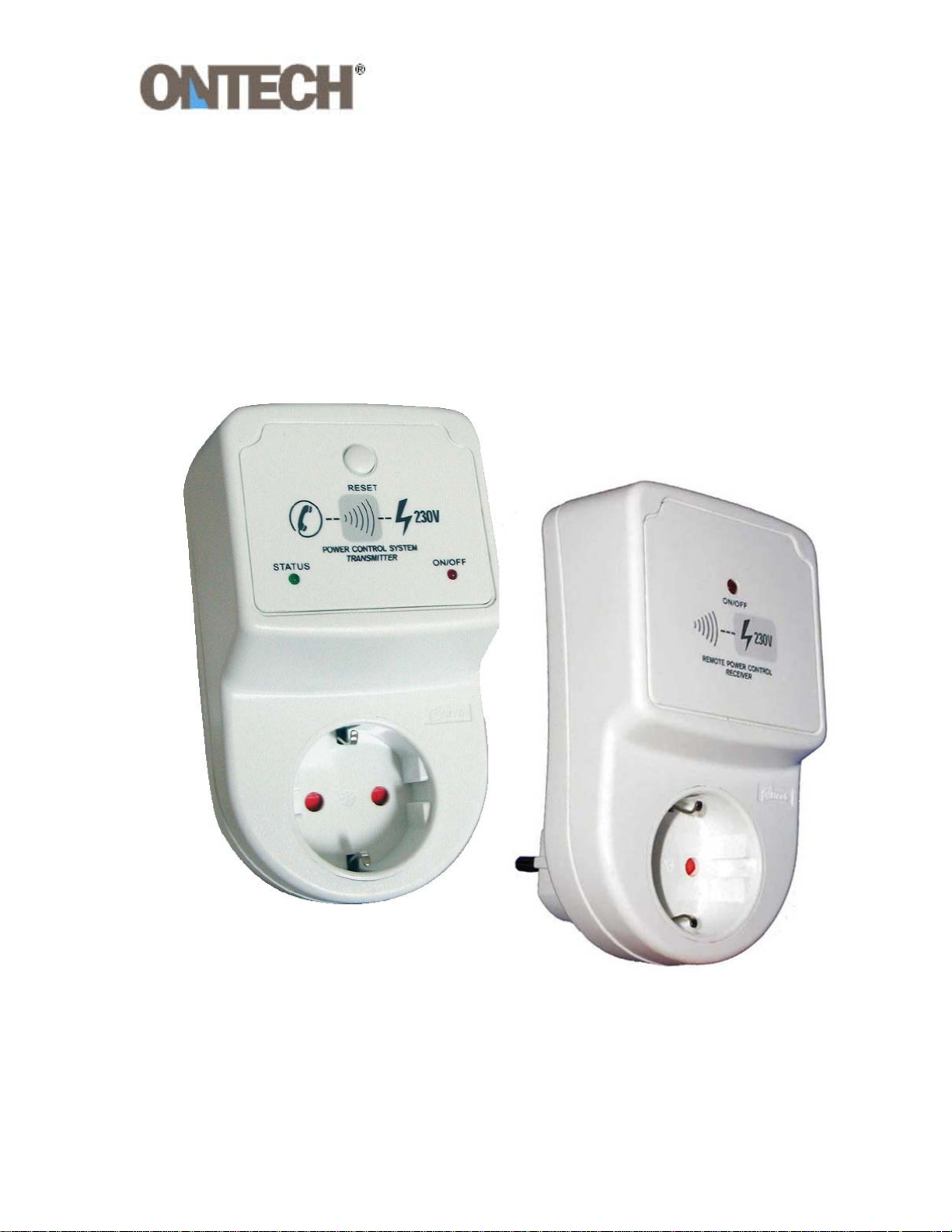
Ontech Teleswitch 9001A
Ontech Extra Switch 9003
Users Manual
Page 2

Welcome
Thank you for choosing Ontech Teleswitch 9001A.
We hope the product will work as you wish and that you will find this manual
correct and easy to follow.
If you have further thoughts or questions regarding the product, visit our
website www.ondico.se
Inquiries can be made at [email protected]
where you can find more information.
.
-2-
Page 3

Contents
Ontech Teleswitch 9001A............................................................. 4
Overview.................................................................................................................................... 4
Contents in the package ...................................................................................................... 4
Contents in the package ...................................................................................................... 5
Connecting the unit............................................................................................................... 5
Controlling the relay.............................................................................................................. 5
Control the relay manually ............................................................................................. 5
Controlling the relay with a telephone ...................................................................... 5
Check position of relay .........................................................................................................6
Check the temperature......................................................................................................... 7
Settings ...................................................................................................................................... 7
Set the access code........................................................................................................... 7
Set the number of rings before settings .................................................................... 8
Reset....................................................................................................................................... 8
Power failure ............................................................................................................................ 9
Thunder storm protection................................................................................................... 9
Functions................................................................................................................................... 9
Commands........................................................................................................................... 9
Reset button......................................................................................................................10
The LEDs..............................................................................................................................10
Acknowledges signals at remote operation...........................................................10
Ontech Extra Switch 9003 ..........................................................11
Overview..................................................................................................................................11
Important about radio communication........................................................................11
Contents in this package....................................................................................................11
Get started ..............................................................................................................................12
ID number of the unit.....................................................................................................12
Set radio channel .............................................................................................................13
Controlling the relay............................................................................................................15
Controlling the relay with a telephone ....................................................................15
Functions.................................................................................................................................16
The LED................................................................................................................................16
Technical specifications.............................................................................. 17
Service/support........................................................................................... 18
Declaration of conformity ..........................................................................18
-3-
Page 4
Ontech Teleswitch 9001A
A
Overview
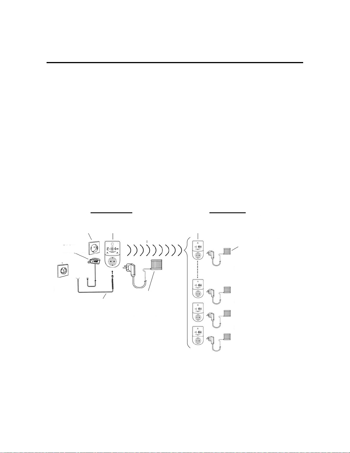
Ontech Teleswitch 9001A has a built-in 230V/16A relay that can be remotely
operated by an ordinary telephone. You can call the unit from any telephone
and operate it and/or extra relays by using the keyboard of the telephone.
To the unit or the extra relay (Ontech Teleswitch 9003) electrical equipment
such as fans, radiators, lamps etc can be connected and turned on or off with a
telephone call.
The unit can also give you information whether the temperature is above or
below 5 degrees C.
Control Unit Extra Switch
Power wa ll socket Control Unit OND-9001A
Telephone
Telephone
Telephone
Control Unit has ID no 1
Välipistokkeet
Norja Tanska Ruotsi Suomi
Radio communication
Equipment to be
controlled
OND-9003 OND-9001A
Extra Switch OND-9003
Equipment to be
controlled
Each Extra Switch can
be given ID number
2, 3, 4 or 5.
n infinite number of
Extra Switches can
be used.
Each Extra Switch m ust
be set to same Radio Channel
as the Control Unit OND9001A
-4-
Page 5

Contents in the package
• Ontech Teleswitch 9001A.
• Cord for connection to the telephone line.
• This manual.
Connecting the unit
There must not be any other equipment that answers calls (answering machine,
fax etc) connected to the telephone line.
1. Connect the telephone cord to the jack on the under side of the unit. A
click shall be heard.
2. Connect the telephone cord to the telephone line.
3. Connect the unit to a main power socket.
4. Connect desired equipment to the socket of the unit. The green LED
starts slowly blinking.
Controlling the relay
Control the relay manually
1. Push the button ”RESET”. The relay turns on and the red LED is lit.
2. Push the button ”RESET” again. The relay turns off and the red LED is
turned off.
Controlling the relay with a telephone
1. Call the unit. Be sure your telephone is set to tone –NOT pulse.
2. After two rings the unit answers with two beeps. Consult Settings if you
want to change the number of rings before the unit answers.
3. Dial *0000# which is your preset access code. If you want to change the
access code to your own unique, consult Settings.
If you do not enter your access code within 15 seconds a long beep will
be heard and the unit is disconnecting the call. If * is pushed, the time
will be extended with 8 seconds for each push.
-5-
Page 6

4. The unit answers with two beeps if the code is correct. If the code is not
correct, the unit answers with a long beep. Try again.
5. Turn on the relay by dialing *1*1#. The unit acknowledges with two
beeps.
6. Turn off the relay by dialing *1*0#. The unit acknowledges with two
beeps.
7. Turn on the relay and program timer, dial *1*1*T# where T indicates
how many hours the relay will be in on position. (1-99 hours can be
chosen). This programming can be done when the relay already is set to
on. The time is counted from the moment the programming is done.
8. To end the call, dial *0#. The unit acknowledges with two beeps and is
hung up.
Check position of relay
Check if the unit (or the extra relays) is set to on or off position.
1. Call up the unit. Be sure your telephone is set to tone –NOT pulse.
2. After two rings the unit answers with two beeps. Consult Settings if you
want to change the number of rings before the unit answers.
3. Dial *0000# which is your preset access code. If you want to change the
access code to your own unique, consult Settings.
If you do not enter your access code within 15 seconds a long beep will
be heard and the unit is disconnecting the call. If * is pushed, the time
will be extended with 8 seconds for each push.
4. The unit answers with two beeps if the code is correct. If the code is not
correct, the unit answers with a long beep. Try again.
5. Dial *1*7#.
If the unit answers with short beeps, the relay is turned on.
If the unit answers with a long beep, the relay is turned off.
9. To the end call, dial *0#. The unit acknowledges with two beeps and is
hung up.
-6-
Page 7

Check the temperature
You can check whether the temperature is above or below 5° C in the place
where the unit is located.
1. Call up the unit. Be sure your telephone is set to tone –NOT pulse.
2. After two rings the unit answers with two beeps. Consult Settings if you
want to change the number of rings before the unit answers.
3. Dial *0000# which is your preset access code. If you want to change the
access code to your own unique, consult Settings.
If you do not enter your access code within 15 seconds a long beep will
be heard and the unit is disconnecting the call. If * is pushed, the time
will be extended with 8 seconds for each push.
4. The unit answers with two beeps if the code is correct. If the code is not
correct, the unit answers with a long beep. Try again.
5. Dial *8#.
If the unit answers with short beeps, the temperature is above 5° C.
If the unit answers with a long beep, the temperature is below 5° C.
10. To end the call, dial *0#. The unit acknowledges with two beeps and is
hung up.
Settings
Set the access code
The default access code is 0000. This can be altered to any four digit number.
1. Call up the unit. Be sure your telephone is set to tone –NOT pulse.
2. After two rings the unit answers with two beeps. Consult Settings if you
want to change the number of rings before the unit answers.
3. Dial *0000# which is your preset access code. If you do not enter your
access code within 15 seconds a long beep will be heard and the unit is
disconnecting the call. If * is pushed, the time will be extended with 8
seconds for each push.
-7-
Page 8

4. The unit answers with two beeps if the code is correct. If the code is not
correct, the unit answers with a long beep. Try again.
5. Dial *9*ABCD#, where ABCD is the new four digit code number. The
unit acknowledges the change with short beeps.
6. To end the call, dial *0#. The unit acknowledges with two beeps and is
hung up.
Set the number of rings before settings
Default setting from factory is two rings before answering..
1. Call up the unit. Be sure your telephone is set to tone –NOT pulse.
2. After two rings the unit answers with two beeps.
3. Dial *0000# which is your preset access code. If you want to change the
access code to your own unique, consult Settings.
If you do not enter your access code within 15 seconds a long beep will
be heard and the unit is disconnecting the call. If * is pushed, the time
will be extended with 8 seconds for each push.
4. The unit answers with two beeps if the code is correct. If the code is not
correct, the unit answers with a long beep. Try again.
5. Dial *6*R#, where R is the number of rings before answer (1-16 rings
can be chosen). The unit the change with short beeps.
6. To end the call, dial *0#. The unit acknowledges with two beeps and is
hung up.
Reset
The unit can be reset to default with access code 0000 and two rings before
answer.
1. Push and hold the RESET-button 10 seconds and the green LED will
turn off.
2. Release the button. The unit is now reset to default.
-8-
Page 9
Power failure
If there is a power failure the relay will be in off position, even when the power is
back.
Also extra switches will be in off position.
It is possible to call the unit and ask for status of relay position. See Check
position of relay.
Thunder storm protection
The unit has a built-in surge protector. If the unit is used on the countryside with
airborne power lines a separate thunder storm protector may be needed. Ask
your local dealer.
Functions
Commands
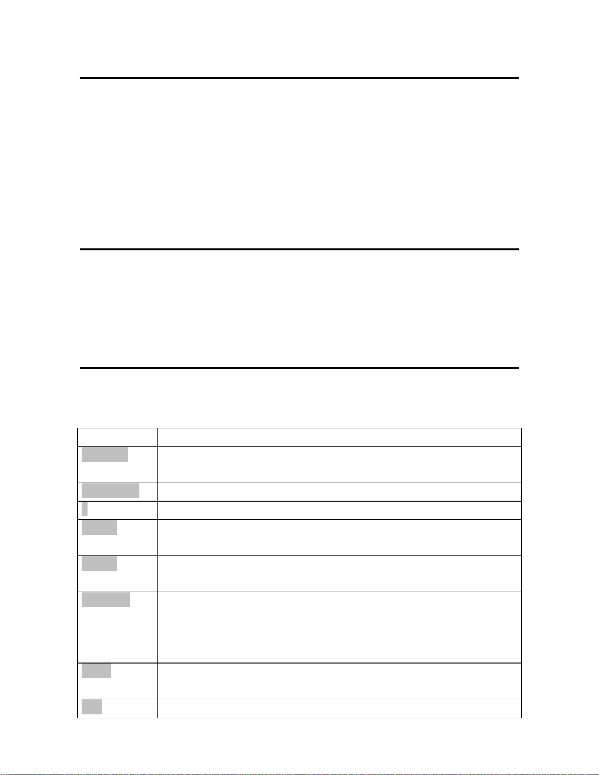
Below you will find a description of all commands.
Command What I means
*ABCD#
*9*EFGH#
*
*N*1#
*N*0#
*N*1*T#
All programming and operation starts with access code (default it
is 0000).
Access code is changed to EFGH (four digit number)
Extend call time with 8 seconds for each push.
Use for turning on the relay. N specifies the ID number of the
Extra Switch.
Use for turning off a relay. N specifies the ID number of the Extra
Switch.
Use for turning on a relay and then automatically turn it off after
a certain time. N specifies the ID number of the Extra Switch, T
specifies time in hours before relay shall be turned off (1-99
N*7#
*8#
hours).
Check position of the relay. N specifies the ID number of the Extra
Switch. Short beeps = on, long beep=off.
Check if temperature is above or below 5°C. Short beeps =
-9-
Page 10
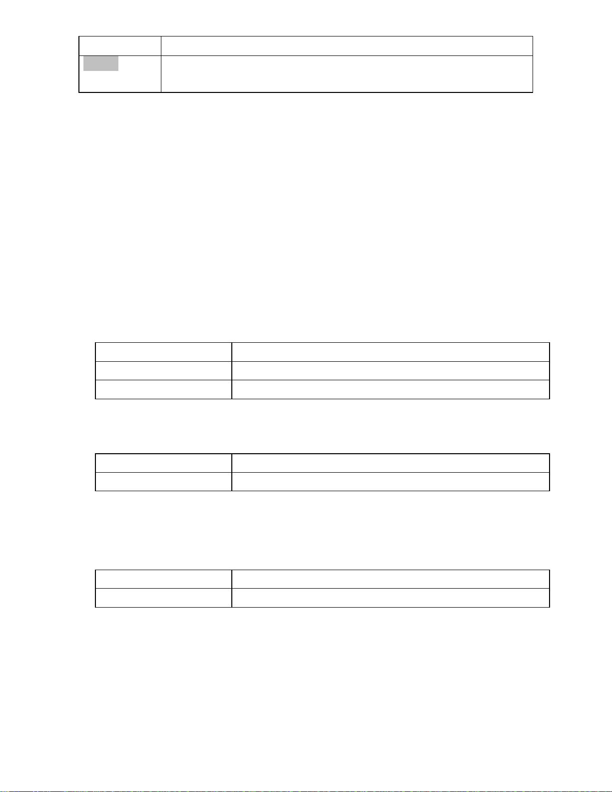
temperature is above 5°C, long beep = below 5°C.
*6*R#
Set number of rings before answer. R indicates the number of
rings (1-16 can be chosen).
Reset button
On the unit there is a push button marked ”RESET”.
• One push changes the position of the relay.
• If the button is pushed and held for 10 seconds (until the green LED
goes off) the unit is reset to factory default.
The LEDs
On the front of the unit, there are two LEDs, one red and one green.
GREEN LED
Fast blink Shown during remote operation
Slow blink The unit is idle
Turned off Reset acknowledges or not connected to power line.
RED LED
On Relay position on
Off Relay position off
Acknowledge signals at remote operation
Short beeps Correct/Yes/OK
Long beep Error/No
-10-
Page 11

Ontech Extra Switch 9003
Overview
Ontech Extra Switch 9003 is controlled by short range radio via the control unit
Ontech Tele Switch 9001A. The unit has a built in 230V/16A relay. Up to 4
Ontech Extra Switches 9003 can individually be controlled by each Ontech
Teleswitch 9001A. The operation range is approximately 30 meters.
Important about radio communication
As for all radio equipment also this radio communication can be interfered by
equipment in the home environment such as TV-sets, refrigerators, mobile
phones, microwaves ovens, electric motors etc . The interference can be
temporary or continuous.
This interference can influence the operating range or make radio controlled
remote operations impossible. This can also results in that the main unit
acknowledges position changing of relays of Extra Switches even if it doesn’t
happen. Also for the function of checking position of relays of Extra Switches
wrong information can be given.
It is important to know this uncertainty for controlling the Extra Switches due to
home environment.
Contents in this package
• Ontech Extra Switch 9003
• This manual
-11-
Page 12
Get started
A condition for starting up the Extra Switch 9003 is that you have a correct
installed Teleswitch 9001A (control unit) which can communicate with one or
more Ontech Extra Switch 9003.
You must set the ID number and the radio channel of the Extra Switch .
ID number of the unit
In a set up with one control unit (Ontech Teleswitch 9001A) and one or more
Ontech Extra Switch 9003, it is important that all units have a unique ID number.
The control unit (Ontech Teleswitch 9001A) is preset to always have ID number
1. The Extra Switches can be set from ID number 2 to 5.
No unit may have ID number 0.
All Extra Switches are set to ID number 2 when delivered.
SETTING ID NUMBER
WARNING. During this operation the unit must not be connected to the power.
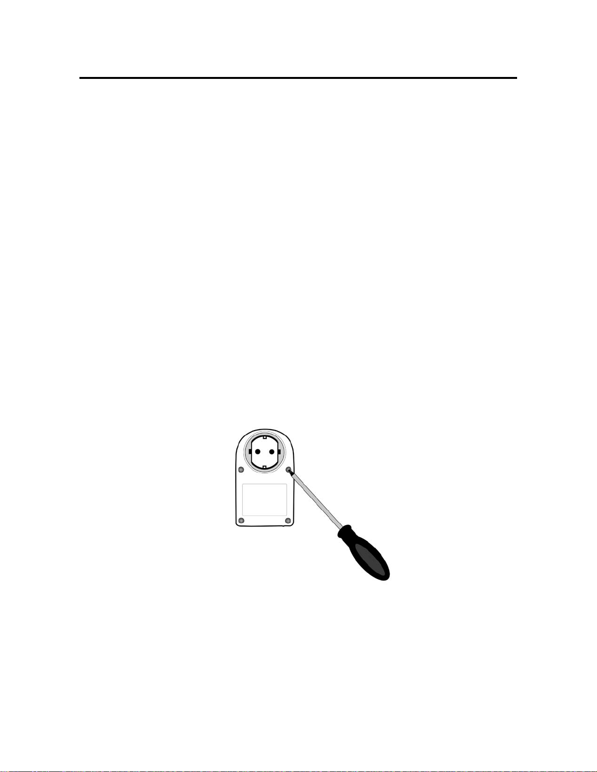
1. Unscrew four screws.
2. Remove the back.
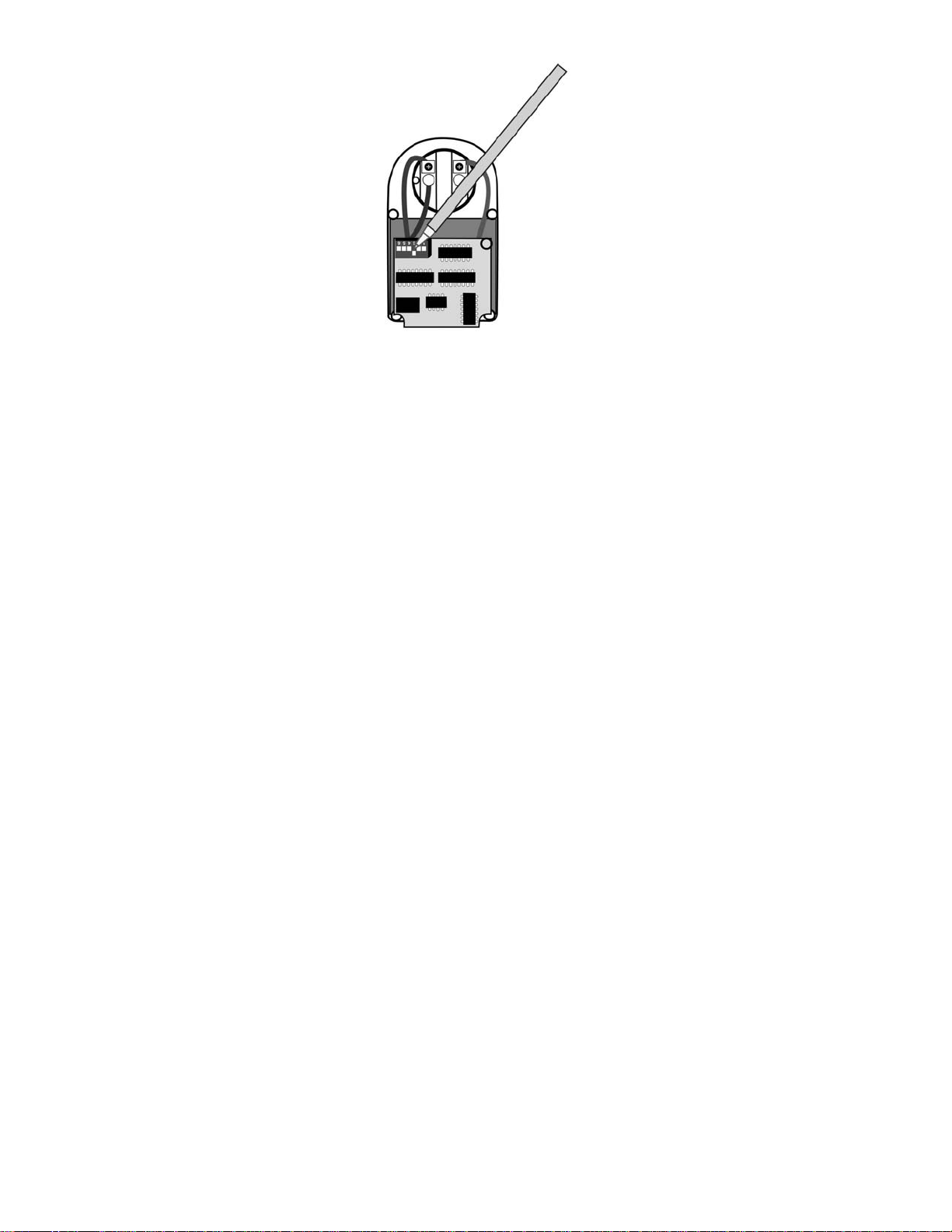
3. Find the DIP-switch (10 small switches on a row). Switch 7-10 is used to
set the ID number of the unit.
IMPORTANT! Only one of the switches should be set in position ON.
-12-
Page 13

4. Set the desired ID number:
Switch 7 ON = ID2
Switch 8 ON = ID3
Switch 9 ON = ID4
Switch 10 ON = ID5
5. Continue with setting radio channel if necessary. See below.
Set radio channel
The system can be set to 64 different radio channels. This can be necessary to do
if there is a similar system in the environment which interferes. Two or more
systems can be run in parallel if the radio channels are different.
Default radio channel is set at factory and is the same in control unit and Extra
Switch.
Only when it is necessary there is a need to change radio channel and it must be
set to the same radio channel on both control unit and all Extra Switches. Which
radio channel you choose is not important, but all units in the system must have
the same.
DIP-switches 1,2,3,4,5 and 6 are used to set the radio channel. Default all are set
to OFF.
SET RADIO CHANNEL ON CONTROL UNIT TELESWITCH 9001A
• WARNING. During this operation the unit must not be connected to
the power.
• Use a screwdriver to remove the screws and remove the back of Ontech
Teleswitch 9001A.
• Find the DIP-switch (6 small switches on a row). DIP-switches 1,2,3,4,5
and 6 is used to set the radio channel.
• Replace the back and the screws
-13-
Page 14
SET RADIO CHANNEL ON EXTRA SWITCHES
• WARNING. During this operation the unit must not be connected to
the power.
• Use a screwdriver to remove the screws and remove the back of Ontech
Extra Switch 9003.
• Find the DIP-switch (10 small switches on a row). DIP-switches 1,2,3,4,5
and 6 are used to set the radio channel.
• It is important that the control unit Ontech Teleswitch 9001A and all
Extra Swithes 9003 are set to the same radio channel..
• Replace the back and the screws.
• Test by calling the unit and operate the relays. See below.
-14-
Page 15

Controlling the relay
With this function you can call up and control the Teleswitch and all Extra
Switches individually.
Connect the unit to desired power socket. Connect the equipment you want to
control.
Important. Check the operating range of the short range radio by calling up
the control unit and operate the Extra Switches. This can easily be done with a
mobile phone when you are installing the system. It is important that you have
some margin for the operating range.
Controlling the relay with a telephone
1. Call the unit. Be sure your telephone is set to tone –NOT pulse.
2. After two rings the unit answers with two beeps. Consult Settings if you
want to change the number of rings before the unit answers.
3. Dial *0000# which is your preset access code. If you want to change
the access code to your own unique, consult Settings.
4. If you do not enter your access code within 15 seconds a long beep will
be heard and the unit is disconnecting the call. If * is pushed, the time
will be extended with 8 seconds for each push.
5. The unit answers with two beeps if the code is correct. If the code is not
correct, the unit answers with a long beep. Try again.
6. Turn on the relay by dialing *N*1#. The unit acknowledges with two
beeps. N specifies the ID number of the Extra Switch.
7. Turn off the relay by dialing *N*0#. The unit acknowledges with two
beeps. N specifies the ID number of the Extra Switch.
8. Turn on the relay and program timer, dial *N*1*T# where T indicates
how many hours the relay shall be in on position. (1-99 hours can be
chosen). This programming can be done when the relay already is set to
on. The time is counted from the moment the programming is done. N
specifies the ID number of the Extra Switch.
9. To end the call, dial *0#. The unit acknowledges with two beeps and is
hanging up.
-15-
Page 16
Functions
The LED
On the front there is a red LED.
On Relay position on
Off Relay position off
-16-
Page 17

Technical specifications
Ontech Teleswitch 9001A
Rated voltage/frequency 230V / 50 Hz
Max load 16A / 3680 W
Switch 1 branch
Temperature control
Temperature range
Requirements Meets requirements of EMC, LVD and RTTE
Approvals Semko, S
Standards LVD EN60669-2-1, EN61058-1
Standards EMC EN50081-1, EN50082-2
5° C (+/- 2° C)
-30° C to +40° C
directives.
Ontech Extra Switch 9003
Rated voltage/frequency 230V / 50 Hz
Max load 16A / 4000 W resistive load, 1E5
Switch 1 branch
Temperature range
-30° C till +40° C
Protection class I
Requirements Meets requirements of EMC, LVD and RTTE
directives.
Approvals Semko, S
Standards LVD IEC60884-2-5:1995, IEC61058-1:2000+A1:2001
Standards EMC EN301489-3/-1:2000
-17-
Page 18
Service/support
If the product needs repair or service, contact the reseller. Information and
support may also be found at www.ondico.se.
Declaration of conformity
Ondico AB, Datavägen 14A, 436 32 Askim, Sweden, hereby declares that the
products Ontech Teleswitch 9001A and Ontech Extra Switch 9003 is in
conformity with the provisions of the Radio & Tele Terminal directive R&TTE
1999/5/EG.
0681
-18-
Page 19

-19-
Page 20

95005_95008_IB_UK_080930
www.ondico.se
-20-
 Loading...