

Page 1

OnSSI NetDVMS 6.5
User Manual
On-Net Surveillance Systems, Inc.
222 Route 59, Suite 303, Suffern, NY 10901
T: 845-369-6400 F: 845-369-8711
www.onssi.com
Page 2

This page intentionally left blank.
Page 3

OnSSI NetDVMS Rev 6.5
Table Of Contents
Table Of Contents
WELCOME.........................................................................................................................................................1
PRODUCT OVERVIEW ........................................................................................................................................ 1
Updates .......................................................................................................................................................2
Software Upgrade Plan (SUP).....................................................................................................................2
SYSTEM REQUIREMENTS ..............................................................................................................................3
SYSTEM REQUIREMENTS ...................................................................................................................................3
Surveillance System Server ........................................................................................................................3
NetGuard-EVS............................................................................................................................................. 4
NetGuard.....................................................................................................................................................4
NetPDA/NetCell Server............................................................................................................................... 5
NetPDA/NetCell Client.................................................................................................................................7
NetMatrix Monitor ........................................................................................................................................7
IMPORTANT PORT NUMBERS..............................................................................................................................8
WINDOWS VISTA INFORMATION..........................................................................................................................8
INSTALLATION.................................................................................................................................................9
INSTALLING THE SOFTWARE...............................................................................................................................9
ADMINISTRATION.......................................................................................................................................... 11
ADMINISTRATOR LOGIN WINDOW ..................................................................................................................... 11
ADMINISTRATOR WINDOW ...............................................................................................................................11
Device Manager Section ...........................................................................................................................12
Adding Devices.......................................................................................................................................... 12
Editing Settings for Devices.......................................................................................................................12
Editing Settings for Cameras.....................................................................................................................12
Renaming a Camera .............................................................................................................................................. 13
Assigning Shortcut Numbers to Cameras............................................................................................................... 13
Editing Settings for Audio Sources............................................................................................................13
Disabling/Enabling Cameras and Audio Sources......................................................................................14
Administrator Window's Buttons................................................................................................................15
IMPORT OF DLKS............................................................................................................................................18
How to Import Device License Keys..........................................................................................................18
DEVICE ADMINISTRATION.................................................................................................................................19
How to Add a Device................................................................................................................................. 19
Edit Device Settings Window.....................................................................................................................22
Identify Video Device Section.................................................................................................................... 22
Network Settings for Video Device Section...............................................................................................24
Camera Settings for [Device Name] Window............................................................................................ 25
P/T/Z Camera Selection Section...............................................................................................................25
Camera List and Fields..............................................................................................................................26
Using DVR Devices................................................................................................................................... 27
CAMERA ADMINISTRATION ...............................................................................................................................28
About Camera Administration ...................................................................................................................28
Adding Cameras..................................................................................................................................................... 28
Configuring Cameras ............................................................................................................................................. 28
Camera Settings for [Device Name] [Camera Name] Window .................................................................29
On-Net Surveillance Systems, Inc. | 222 Route 59, Suite 303, Suffern, NY 10901 | T: 845-369-6400 | F: 845-369-8711 | www.onssi.com | [email protected] | page iii
Page 4

OnSSI NetDVMS Rev 6.5
Table Of Contents
Speedup Settings ...................................................................................................................................... 29
Recording Settings .................................................................................................................................... 30
Live Settings..............................................................................................................................................32
Audio..........................................................................................................................................................32
IPIX............................................................................................................................................................33
Motion Detection Settings..........................................................................................................................33
Database Settings ..................................................................................................................................... 33
Image Quality.............................................................................................................................................36
Event Notifications.....................................................................................................................................36
Outputs......................................................................................................................................................36
PTZ Preset Positions... (PTZ Cameras Only) ...........................................................................................36
Configure Device Window......................................................................................................................... 37
Camera Settings Section...........................................................................................................................37
Include Date and Time in Image............................................................................................................................. 37
Preview Image...........................................................................................................................................38
Adjust Motion Detection Window...............................................................................................................38
Noise Sensitivity ........................................................................................................................................39
Motion Sensitivity....................................................................................................................................... 39
Define Exclusion Regions Window............................................................................................................ 40
Defining Areas in which Motion Detection Should Be Disabled................................................................40
Define Exclusion Regions Window's Buttons and Check Boxes...............................................................41
Output Settings for [Device Name] [Camera Name] Window ...................................................................42
Associating Outputs with Manual Control and Detected Motion...............................................................42
Selecting Output for Manual Control ......................................................................................................................43
Selecting Output for Use on Motion Detection........................................................................................................ 43
Setup Notifications on Events Window...................................................................................................... 44
What Is an Event Indication?.....................................................................................................................44
Specifying Events for which Event Indication Should Be Used.................................................................45
PTZ Pre .....................................................................................................................................................45
Set Positions for [Device Name] [Camera Name] Window ....................................................................... 46
Why Use Preset Positions?.......................................................................................................................46
Absolute and Relative Positioning PTZ Cameras .....................................................................................46
How to Define a Preset Position................................................................................................................47
PTZ Preset Positions for [Device Name] [Camera Name] Window's Sections.........................................47
PTZ View Section......................................................................................................................................47
Preset Positions Section............................................................................................................................49
Preset Position on Events Section ............................................................................................................50
Patrolling Section....................................................................................................................................... 50
Event Window (for PTZ Preset Positions on Event)..................................................................................51
Associating Preset Positions with Particular Events .................................................................................51
Setup PTZ Patrolling Window....................................................................................................................52
Patrol Scheme...........................................................................................................................................52
Defining a New Patrol Scheme............................................................................................................................... 52
Copying an Existing Patrol Scheme....................................................................................................................... 53
Renaming an Existing Patrol Scheme.................................................................................................................... 53
Removing an Existing Patrol Scheme .................................................................................................................... 53
Selecting Preset Positions to Be Used for a PTZ Patrol Scheme.............................................................53
Specifying Timing Settings for a PTZ Patrol Scheme ...............................................................................54
PTZ Patrolling Actions on Detected Motion...............................................................................................54
PTZ Scanning............................................................................................................................................54
iPIX Camera Configuration Window..........................................................................................................55
IPIX View Adjustment................................................................................................................................56
Previewing the IPIX View ..........................................................................................................................57
On-Net Surveillance Systems, Inc. | 222 Route 59, Suite 303, Suffern, NY 10901 | T: 845-369-6400 | F: 845-369-8711 | www.onssi.com | [email protected] | page iv
Page 5

OnSSI NetDVMS Rev 6.5
Table Of Contents
Ceiling Mounted Cameras...................................................................................................................................... 57
Setting a View as Home Position ...........................................................................................................................57
Image Resolution.......................................................................................................................................57
Camera Name and Number Window ........................................................................................................58
AUDIO SOURCE ADMINISTRATION.....................................................................................................................59
Important Information about Using Audio..................................................................................................59
Microphone Settings Window....................................................................................................................60
Speaker Settings Window .........................................................................................................................60
RECORDING SERVER SERVICE MANAGEMENT...................................................................................................61
Using the Recording Server Manager.......................................................................................................61
Start the Recording Server........................................................................................................................ 62
Stop the Recording Server........................................................................................................................62
Open the NetDVMS Application................................................................................................................63
Show the System Status ...........................................................................................................................63
Show the Recording Server Log File.........................................................................................................64
Show the Image Server Log File...............................................................................................................64
Open the Build-in Help System .................................................................................................................64
About NetDVMS ........................................................................................................................................ 64
Exit the Recording Server Manager .......................................................................................................... 64
Service Manager Window..........................................................................................................................65
Pausing the Recording Server Service .....................................................................................................65
Resuming the Recording Server Service ..................................................................................................65
What to Do if the Recording Server Service is Stopped ...........................................................................65
SCHEDULING................................................................................................................................................... 66
Camera/Alert Scheduler Window ..............................................................................................................66
Camera/Alert Scheduler Window's Fields and Check Boxes....................................................................67
Camera/Alert Scheduler Window's Calendar Section...............................................................................69
Set and Clear Modes.............................................................................................................................................. 69
Zoom Feature.........................................................................................................................................................69
How to Set or Clear Periods in the Calendar ............................................................................................69
Good to Know when You Set Online Periods......................................................................................................... 69
Good to Know when You Set Patrolling Periods ....................................................................................................70
Colored Bars ..........................................................................................................................................................70
Camera/Alerts Scheduler Window's Copy and Paste Buttons.................................................................. 71
GENERAL SETTINGS........................................................................................................................................72
General Settings Window..........................................................................................................................72
Administrator Settings ...............................................................................................................................72
Changing the Administrator Password ................................................................................................................... 72
Manual Start Recording Settings............................................................................................................... 72
Patrolling Settings......................................................................................................................................73
Logfile Settings..........................................................................................................................................73
Logfile Path ............................................................................................................................................................73
Days to Log............................................................................................................................................................ 73
Event Recording Settings..........................................................................................................................74
Path........................................................................................................................................................................ 74
Days to Keep.......................................................................................................................................................... 74
Advanced...................................................................................................................................................75
Email Settings............................................................................................................................................75
SMS Settings.............................................................................................................................................75
Change Password Window .......................................................................................................................76
How to Change the Administrator Password.............................................................................................76
E-Mail Setup Window................................................................................................................................76
Enabling E-Mail Alerts ............................................................................................................................... 77
Specifying Recipients ................................................................................................................................ 78
On-Net Surveillance Systems, Inc. | 222 Route 59, Suite 303, Suffern, NY 10901 | T: 845-369-6400 | F: 845-369-8711 | www.onssi.com | [email protected] | page v
Page 6

OnSSI NetDVMS Rev 6.5
Table Of Contents
Specifying Sender Settings .......................................................................................................................78
Specifying Default Subject and Message Texts........................................................................................78
Specifying Image and Interval Options......................................................................................................79
Testing Your E-Mail Alert Configuration.................................................................................................... 79
SMS Settings Window............................................................................................................................... 79
Enabling SMS Alerts..................................................................................................................................80
Specifying SMS Alert Settings...................................................................................................................80
Testing Your SMS Alert Configuration.......................................................................................................80
INPUT, EVENTS & OUTPUT...............................................................................................................................81
About Input, Events & Output ...................................................................................................................81
Types of Events...................................................................................................................................................... 81
Specifying Input, Events and Output ...................................................................................................................... 82
Using Dedicated I/O Devices.....................................................................................................................83
I/O Setup....................................................................................................................................................83
I/O Setup Window ..................................................................................................................................................83
I/O Setup Window's Defined Events List and Buttons...............................................................................84
Add New Event Window (Devices With One Input Event)...................................................................................... 87
Add New Event Window's Fields...............................................................................................................88
Multiple Input Events Window ................................................................................................................................ 89
Multiple Input Events Window's Fields and Buttons..................................................................................89
Add New Event Window (Devices With Several Input Events)............................................................................... 90
Add New Event Window's Fields...............................................................................................................91
Edit Event Window (for Editing Input Events)......................................................................................................... 92
Edit Event Window's Fields .......................................................................................................................92
New Timer Window ................................................................................................................................................ 94
New Timer Window's Fields ......................................................................................................................95
Add New Output Window ....................................................................................................................................... 96
Add New Output Window's Fields.............................................................................................................96
Testing the Defined Output........................................................................................................................97
Edit Output Window................................................................................................................................................ 97
Edit Output Window's Fields...................................................................................................................... 98
Testing the Defined Output........................................................................................................................99
Advanced Window.................................................................................................................................................. 99
Advanced Window's Fields......................................................................................................................100
Event Buttons ..........................................................................................................................................101
About Event Buttons ............................................................................................................................................ 101
Event Buttons Window ......................................................................................................................................... 102
Defined Events List..................................................................................................................................102
Specifying Event Buttons and Timer Events...........................................................................................103
Editing Event Buttons and Timer Events.................................................................................................104
Associating Event Buttons with External Outputs ...................................................................................104
Add New Event Window (for Adding Event Buttons)............................................................................................ 104
Add New Event Window's Fields.............................................................................................................105
Edit Event Window (for Editing Event Buttons)..................................................................................................... 106
Edit Event Window's Fields .....................................................................................................................106
Generic Events........................................................................................................................................107
Generic Events Window....................................................................................................................................... 107
Generic Events Window's Events List and Buttons.................................................................................108
Add New Event Window (for Specifying Generic Events)..................................................................................... 109
General Event Settings Section...............................................................................................................110
Event Rule String Section........................................................................................................................111
Notification Settings Section....................................................................................................................114
Edit Event Window (for Editing Generic Events) .................................................................................................. 115
General Event Settings Section...............................................................................................................116
On-Net Surveillance Systems, Inc. | 222 Route 59, Suite 303, Suffern, NY 10901 | T: 845-369-6400 | F: 845-369-8711 | www.onssi.com | [email protected] | page vi
Page 7

OnSSI NetDVMS Rev 6.5
Table Of Contents
Event Rule String Section........................................................................................................................117
Notification Settings Section....................................................................................................................120
I/O Control ...............................................................................................................................................121
I/O Control Window .............................................................................................................................................. 121
Associating Events with Particular Outputs.............................................................................................121
Output Settings for [Device Name] [Camera Name] Window............................................................................... 122
Associating Outputs with Manual Control and Detected Motion.............................................................123
How to .....................................................................................................................................................125
... Add an Event Button......................................................................................................................................... 125
... Add an Input-Based Event................................................................................................................................ 127
... Add a VMD Event............................................................................................................................................. 129
... Add a Generic Event ........................................................................................................................................ 131
... Test a Generic Event........................................................................................................................................ 133
... Add a Timer Event............................................................................................................................................ 135
... Add a Manually Controlled Output.................................................................................................................... 137
... Add a Motion-Triggered Output........................................................................................................................ 140
ARCHIVING....................................................................................................................................................144
About Archiving........................................................................................................................................144
Benefits of Archiving................................................................................................................................144
How Archiving Works ..............................................................................................................................144
Storing Archives at Other Locations than the Default Archiving Directory............................................................ 145
Archiving Audio ....................................................................................................................................................145
Automatic Archiving if Running Out of Disk Space............................................................................................... 145
Storage Capacity Required for Archiving................................................................................................ 146
Backing Up Archives ...............................................................................................................................146
Viewing Archived Recordings..................................................................................................................146
Archives Stored Locally or on Network Drives...................................................................................................... 146
Exported Archives................................................................................................................................................ 147
Archive Setup Window ............................................................................................................................147
Archive Setup Window's Fields and Buttons...........................................................................................148
Specifying that Archiving Should Apply for Specific Cameras.............................................................................. 150
Archiving Locations for Individual Cameras (Static archiving).............................................................................. 150
Static Archiving........................................................................................................................................151
Dynamic Archiving...................................................................................................................................152
Archiving Audio........................................................................................................................................153
NETMATRIX ADMINISTRATION ........................................................................................................................154
NetMatrix Configuration Window.............................................................................................................154
Config Tab...............................................................................................................................................154
Event Tab ................................................................................................................................................156
IMAGE SERVER ADMINISTRATION...........................................................................................................158
IMAGESERVER ADMINISTRATOR WINDOW.......................................................................................................158
Server Configuration Section...................................................................................................................159
User Administration Section....................................................................................................................161
Defining Users.........................................................................................................................................161
Defining User Access Rights................................................................................................................... 161
Full Access for All Users....................................................................................................................................... 161
Restricted Access................................................................................................................................................. 161
Master/Slave Setup Section....................................................................................................................161
Configuration on the Master Server.........................................................................................................162
Configuration on a Slave Server..............................................................................................................162
Not Using a Master/Slave Setup .............................................................................................................162
Upgrading Servers in an Existing Master/Slave Setup............................................................................162
Keep Transition Period as Short as Possible ....................................................................................................... 163
On-Net Surveillance Systems, Inc. | 222 Route 59, Suite 303, Suffern, NY 10901 | T: 845-369-6400 | F: 845-369-8711 | www.onssi.com | [email protected] | page vii
Page 8

OnSSI NetDVMS Rev 6.5
Table Of Contents
Log Files Section.....................................................................................................................................163
Audit Log Section.....................................................................................................................................163
Language Support and XML Encoding Section ...................................................................................... 164
Good to know: Remote Viewing of Live Images from Stopped Cameras...............................................164
DEFINE LOCAL IP RANGES WINDOW ..............................................................................................................165
USER ADMINISTRATION WINDOW ...................................................................................................................166
Prerequisites............................................................................................................................................167
User and Group Concepts.......................................................................................................................167
Users.................................................................................................................................................................... 167
Groups.................................................................................................................................................................. 167
How to Add a New Basic User ................................................................................................................168
How to Add a New Windows User or Group...........................................................................................168
How to Edit an Existing User Name or Password...................................................................................169
How to Remove an Existing User............................................................................................................169
What Information to Provide to Users......................................................................................................169
NetGuard Users.......................................................................................................................................169
NetGuard-EVS Users..............................................................................................................................170
DEFINE USER RIGHTS WINDOW .....................................................................................................................172
SLAVE ADMINISTRATION WINDOW.................................................................................................................. 175
Adding a Slave Server.............................................................................................................................175
Removing a Slave Server........................................................................................................................175
VIDEO CLIENTS............................................................................................................................................176
VIDEO CLIENT OVERVIEW.............................................................................................................................. 176
Server End: Providing Access through a NetGuard or NetGuard-EVS...................................................177
Server End: Providing Access Through a NetPDA/NetCell Client..........................................................177
DECIDING WHICH VIDEO CLIENT TO USE ........................................................................................................178
Test Your Organization's Needs..............................................................................................................178
What is .Net?...........................................................................................................................................178
Differences between NetGuard and NetGuard-EVS...............................................................................179
NETGUARD-EVS ..........................................................................................................................................181
NetGuard-EVS Introduction.....................................................................................................................181
Installing the NetGuard-EVS ...................................................................................................................181
Removing the NetGuard-EVS .................................................................................................................181
Installation................................................................................................................................................182
Download and Installation from Server................................................................................................................. 182
Installation from CD.............................................................................................................................................. 182
Silent Installation.................................................................................................................................................. 183
NETGUARD...................................................................................................................................................184
NetGuard Introduction.............................................................................................................................184
What Are Remote Users Able to Do with the NetGuard?........................................................................184
How Does the NetGuard Get Video from the Surveillance System?......................................................184
How Can User Rights Affect Use of the NetGuard?................................................................................184
How Does the NetGuard Differ from the NetGuard-EVS? ...................................................................... 185
Downloading and Installing NetGuard.....................................................................................................185
Downloading and Installing the NetGuard...............................................................................................185
Installing the NetGuard from CD .............................................................................................................186
Accessing the NetGuard Client ...............................................................................................................186
Accessing a NetGuard Run from Server................................................................................................. 186
Accessing a Locally Installed NetGuard..................................................................................................187
Upon Accessing the NetGuard: Logging In............................................................................................. 187
If You Log in for the First Time............................................................................................................................. 188
Logging in on Different Computers.......................................................................................................................188
On-Net Surveillance Systems, Inc. | 222 Route 59, Suite 303, Suffern, NY 10901 | T: 845-369-6400 | F: 845-369-8711 | www.onssi.com | [email protected] | page viii
Page 9

OnSSI NetDVMS Rev 6.5
Table Of Contents
Creating Views.........................................................................................................................................189
Are Any Views in Shared Groups Available?..........................................................................................189
Which Types of Groups are You Able to Create Views in?.....................................................................190
Creating Views in Private Groups............................................................................................................190
Creating a Private Group......................................................................................................................................191
Creating a View in a Private Group...................................................................................................................... 191
Adding Cameras to the View................................................................................................................................ 191
Creating Views in Shared Groups...........................................................................................................192
Creating a Shared Group ..................................................................................................................................... 192
Creating a View in a Shared Group...................................................................................................................... 193
Adding Cameras to the View................................................................................................................................ 193
Using Your Views on Different Computers........................................................................................................... 194
Further Configuration...............................................................................................................................194
Which Types of Groups are You Able to Edit Views in? .........................................................................194
Using Static Images in Views..................................................................................................................195
Using HTML Pages in Views...................................................................................................................195
Renaming Groups....................................................................................................................................196
Deleting Groups.......................................................................................................................................196
Renaming Views...................................................................................................................................... 196
Deleting Views.........................................................................................................................................196
Adjusting Camera Settings...................................................................................................................... 197
Image Quality....................................................................................................................................................... 197
Frame Rate ..........................................................................................................................................................197
IPIX Split Mode..................................................................................................................................................... 197
Apply to All ........................................................................................................................................................... 197
Configuring Joystick Control....................................................................................................................198
Viewing Live Images................................................................................................................................199
Selecting a View......................................................................................................................................199
Image Bars ..............................................................................................................................................199
Enlarging Images from Particular Cameras in a View.............................................................................201
Output Control .........................................................................................................................................201
PTZ Control .............................................................................................................................................201
Point-and-Click Control......................................................................................................................................... 202
PTZ Navigation Buttons........................................................................................................................................ 202
PTZ Preset Positions............................................................................................................................................ 202
IPIX PTZ Positions............................................................................................................................................... 202
Viewing Recorded Images.......................................................................................................................203
Selecting a View......................................................................................................................................203
Enlarging Images from Particular Cameras in a View.............................................................................203
Time Navigation.......................................................................................................................................204
Master Time Area.................................................................................................................................................204
Browse Buttons.................................................................................................................................................... 204
Time Sliders .........................................................................................................................................................204
Playback Slider and Buttons................................................................................................................................. 205
Go To Time .......................................................................................................................................................... 205
Sequences...............................................................................................................................................205
PTZ Control .............................................................................................................................................206
Point-and-Click Control......................................................................................................................................... 206
PTZ Navigation Buttons........................................................................................................................................ 206
PTZ Preset Positions............................................................................................................................................ 206
IPIX PTZ Preset Positions.................................................................................................................................... 206
Printing Images........................................................................................................................................206
Exporting Images..................................................................................................................................... 207
Exporting Video Evidence .......................................................................................................................208
Keyboard Shortcuts.................................................................................................................................211
On-Net Surveillance Systems, Inc. | 222 Route 59, Suite 303, Suffern, NY 10901 | T: 845-369-6400 | F: 845-369-8711 | www.onssi.com | [email protected] | page ix
Page 10

OnSSI NetDVMS Rev 6.5
Table Of Contents
On All Tabs:.......................................................................................................................................................... 211
On Live Tab Only: ................................................................................................................................................211
On Browse Tab Only:........................................................................................................................................... 211
Using an HTML Page for NetGuard Navigation......................................................................................212
Example of an HTML Page with Button Navigation ................................................................................212
Example of an HTML Page with Image Map Navigation.........................................................................214
Importing the HTML Page .......................................................................................................................215
System Administrator's Check List..........................................................................................................216
Logging Out of NetGuard ........................................................................................................................216
NETPDA/NETCELL CLIENT & SERVER ...........................................................................................................217
NetPDA/NetCell Client & Server Introduction..........................................................................................217
NetPDA/NetCell Server...........................................................................................................................217
NetPDA/NetCell Client.............................................................................................................................217
Moving on ...............................................................................................................................................218
Installing & Configuring the NetPDA/NetCell Server...............................................................................218
Installing IIS and .Net Framework ...........................................................................................................218
IIS Installation ....................................................................................................................................................... 218
.NET Framework Verification................................................................................................................................ 219
Allowing Use of .NET Framework (Windows 2003 Only)......................................................................................220
.NET Framework Registration.............................................................................................................................. 221
Installing the NetPDA/NetCell Server......................................................................................................221
IIS Port Configuration........................................................................................................................................... 221
NetPDA/NetCell Server Installation...................................................................................................................... 223
Verifying the NetPDA/NetCell Server Installation....................................................................................224
NetPDA/NetCell Server Installation Troubleshooting..............................................................................225
NetPDA/NetCell Server Cannot Be Installed........................................................................................................ 225
Test Interface Cannot Be Displayed.....................................................................................................................225
Test Interface Is Displayed, but It Is Not Possible to Log In................................................................................. 225
Installing & Configuring the NetPDA/NetCell Client ................................................................................226
Installing the NetPDA/NetCell Client....................................................................................................... 226
Checking the Wireless Connection..........................................................................................................226
Starting and Configuring the NetPDA/NetCell Client...............................................................................227
Using the NetPDA/NetCell Client ............................................................................................................ 229
Starting the NetPDA/NetCell Client.........................................................................................................229
Logging In to the NetPDA/NetCell Client.................................................................................................229
Viewing Live Video .................................................................................................................................. 230
Selecting a Camera for Live Viewing.................................................................................................................... 230
Full Screen View ..................................................................................................................................................231
PTZ Control.......................................................................................................................................................... 232
PTZ Preset Positions............................................................................................................................................ 232
Output Control...................................................................................................................................................... 232
Returning to the Camera List Page...................................................................................................................... 232
Viewing Recorded Video.........................................................................................................................233
Selecting a Camera for Viewing of Recordings.................................................................................................... 233
Browsing and Playing Back Recorded Video ....................................................................................................... 234
Finding Recordings from a Specific Time and Date ............................................................................................. 234
Finding Recordings from a Specific Event............................................................................................................ 235
Full Screen View ..................................................................................................................................................235
Returning to the Camera List Page...................................................................................................................... 236
Logging Out of the NetPDA/NetCell Client..............................................................................................236
VIEWER.........................................................................................................................................................237
VIEWER INTRODUCTION................................................................................................................................. 237
MONITOR ...................................................................................................................................................... 238
On-Net Surveillance Systems, Inc. | 222 Route 59, Suite 303, Suffern, NY 10901 | T: 845-369-6400 | F: 845-369-8711 | www.onssi.com | [email protected] | page x
Page 11

OnSSI NetDVMS Rev 6.5
Table Of Contents
WHERE IS THE MONITOR APPLICATION?.........................................................................................................238
NETMATRIX MONITOR................................................................................................................................239
NETMATRIX MONITOR INTRODUCTION............................................................................................................239
INSTALLING THE NETMATRIX MONITOR APPLICATION ...................................................................................... 240
CONFIGURING THE NETMATRIX MONITOR APPLICATION .................................................................................. 241
First Time Configuration..........................................................................................................................241
Changing the Configuration of a Running NetMatrix Monitor..................................................................245
DAY-TO-DAY USE OF THE NETMATRIX MONITOR APPLICATION........................................................................246
Opening the NetMatrix Monitor Window..................................................................................................246
1×1 and 2×2 View....................................................................................................................................246
Camera Information.................................................................................................................................247
Image Aspect Ratios ...............................................................................................................................247
Toggling between Regular and Full Screen View ...................................................................................248
Changing the Configuration of a Running NetMatrix Monitor..................................................................248
Accepting Received Commands .............................................................................................................248
Alerts upon Executed Commands...........................................................................................................249
Shortcut Menus........................................................................................................................................249
NetMatrix Monitor Window Shortcut Menu..............................................................................................249
Notification Area Shortcut Menu..............................................................................................................250
Shutting Down the NetMatrix Monitor Application...................................................................................250
LOGGING ...................................................................................................................................................... 252
ABOUT LOGGING...........................................................................................................................................252
Log File Types, Locations and Names.................................................................................................... 252
Administrator Application Log Files.........................................................................................................252
Event Log Files........................................................................................................................................252
Image Server Service Log Files ..............................................................................................................252
Image Server Service Audit Log Files..................................................................................................... 253
Web Server Log Files.............................................................................................................................. 253
Image Import Service Log Files...............................................................................................................253
Export Log Files.......................................................................................................................................253
Log File Structures ..................................................................................................................................254
Integrity Checks and Possible Error Messages.......................................................................................254
VIDEO DEVICE DRIVERS.............................................................................................................................256
UPDATING VIDEO DEVICE DRIVERS................................................................................................................256
Removing Old Version of Video Device Drivers......................................................................................256
Installing New Version of Video Device Drivers......................................................................................256
REMOVAL ..................................................................................................................................................... 258
REMOVING NETGUARD-EVS .........................................................................................................................258
REMOVING NETGUARD..................................................................................................................................258
REMOVING THE NETMATRIX MONITOR APPLICATION .......................................................................................258
REMOVING THE NETPDA/NETCELL SOFTWARE.............................................................................................. 259
NetPDA/NetCell Server Removal Procedure.......................................................................................... 259
NetPDA/NetCell Client Removal Procedure............................................................................................259
Removing the NetPDA/NetCell Client Directly from the PDA .................................................................259
Removing the NetPDA/NetCell Client from a PC with ActiveSync..........................................................260
On-Net Surveillance Systems, Inc. | 222 Route 59, Suite 303, Suffern, NY 10901 | T: 845-369-6400 | F: 845-369-8711 | www.onssi.com | [email protected] | page xi
Page 12

OnSSI NetDVMS Rev 6.5
Welcome
Product Overview
NetDVMS is a powerful and intelligent surveillance solution:
• Compatible with a wide range of different IP video products from the leading manufacturers, so
you choose the hardware you want—in combinations too
• Dependable; with robust and stable performance proven in operation on thousands of cameras
worldwide
• Flexible; with remote access features that let you use the surveillance system from any place and
at any time
• Scalable; with open architecture based on IP technology with ongoing development and regular
updates, which gives you long-term returns on your surveillance investment
• Future-safe; the IP network approach is the foundation for tomorrow; available today
NetDVMS consists of a number of components, each targeted at specific tasks and user types:
• The Administrator: The main application used by surveillance system administrators for
configuring the NetDVMS surveillance system server, upon installation or whenever configuration
adjustments are required, e.g. when adding new cameras or users to the system.
• The Recording Server: A vital part of the surveillance system; video streams are only
transferred to NetDVMS while the recording server is running. The recording server is
automatically installed as a service (the Recording Server service), which will run in the
background on the NetDVMS surveillance system server. You are able to manage the service
through the Recording Server Manager
• The Image Server: Handles access to the surveillance system for remote users logging in with
the NetGuard, or NetGuard-EVS, or NetPDA/NetCell Client. The Image Server itself does not
require separate hardware; it runs as a service on the surveillance system server. Surveillance
system administrators handle Image Server configuration, including remote users' access rights,
through the Image Server Administrator application.
• NetGuard and NetGuard-EVS: Choice of two types of remote access clients, each providing
users with intuitive remote access to the surveillance system. The NetGuard and NetGuard-EVS
let users view live images, play back recorded images, activate outputs, print and export
evidence, etc. The NetGuard can be downloaded from the surveillance system server and installed
locally on remote users' PCs, or the users can access it straight from the surveillance system
server through an Internet Explorer browser. The extra feature-rich NetGuard-EVS should always
be downloaded and installed on remote users' PCs.
• The NetPDA/NetCell Client and NetPDA/NetCell Server: Enable remote access to the
NetDVMS surveillance system via a PDA or Smartphone with a wireless connection.
.
Welcome
On-Net Surveillance Systems, Inc. | 222 Route 59, Suite 303, Suffern, NY 10901 | T: 845-369-6400 | F: 845-369-8711 | www.onssi.com | [email protected] | page 1
Page 13
OnSSI NetDVMS Rev 6.5
Welcome
• NetMatrix: Integrated product, enabling control of live camera views on remote computers for
distributed viewing. Once configured, NetMatrix-triggered live video can be viewed in cnames or
on computers with the NetMatrix Monitor client application installed.
Updates
OnSSI regularly releases service updates for its products, offering improved functionality and support for
new devices.
If you are an OnSSI system administrator, it is recommended that you check the OnSSI website
www.onssi.com for updates at regular intervals in order to make sure you are using the most recent
version of OnSSI.
Software Upgrade Plan (SUP)
As the cornerstone of its support to customers, OnSSI offers a Software Upgrade Plan (SUP). The purpose
of the SUP is to provide you with lower cost alternative to standard Software upgrades.
SUP coverage can easily be purchased together with most new OnSSI products, but cannot be purchased
as an add-on to a previously purchased product.
During the period covered by the SUP, customers are entitled to receive all generally-released new
versions of their OnSSI software, including both interim and major releases, changes, service packs and
any patches for the product.
Having a valid SUP may easily lead to measurable savings for your organization: The standard cost of a
product upgrade (for example from version X.1 to X.2) is normally 35% of the full product’s
recommended retail price for a single upgrade; depending on the product, the whole SUP cost per year is
much lower then the above single software upgrade, and you will be entitle to receive as many upgraded
released in the covered period.
1, 2 and 3-year SUPs are available for NetDVMS.
© 2002-2008 On-Net Surveillance Systems, Inc. All rights reserved.
NetDVMS, NetEVS, NetDVR, NetGuard, NetGuard-EVS, NetSwitcher, NetMatrix, NetCentral, NetTransact, NetPDA
and NetCell are trademarks of On-Net Surveillance Systems, Inc.
All other trademarks are property of their respective owners.
On-Net Surveillance Systems, Inc. reserves the right to change product specifications without prior notice.
On-Net Surveillance Systems, Inc. | 222 Route 59, Suite 303, Suffern, NY 10901 | T: 845-369-6400 | F: 845-369-8711 | www.onssi.com | [email protected] | page 2
Page 14

OnSSI NetDVMS Rev 6.5
System Requirements
System Requirements
System Requirements
The following are minimum system requirements for running NetDVMS and associated applications:
• Surveillance System Server
Operating
System
Microsoft® Windows® XP Professional (32 bit or 64 bit*) and Windows
Server 2003 (32 bit or 64 bit*), Windows Vista® Business (32 bit or 64
bit*), Windows Vista Enterprise (32 bit or 64 bit*) and Windows Vista
Ultimate (32 bit or 64 bit*).
CPU Intel® Pentium® 4, 2.4 GHz or higher (Core
RAM Minimum 1 GB (2 GB or more recommended).
Network Ethernet (1 Gbit recommended).
Graphics
Adapter
Hard Disk Type E-IDE, PATA, SATA, SCSI, SAS (7200 RPM or faster).
Hard Disk Space Minimum 80 Gbyte free (depends on number of cameras and recording
Software DirectX 9.0 or newer required to run Playback Viewer application.
* Running as a 32 bit service/application.
Tip: To check which DirectX version is installed on a computer, click Start, select Run..., and
type dxdiag. When you click OK, the DirectX Diagnostic Tool window will open; version
information is displayed near the bottom of its System tab. Should the server require a DirectX
update, the latest versions of DirectX are available from http://www.microsoft.com/downloads/
Tip: Information about how to verify/install Microsoft .Net Framework and IIS versions is
available in Installing & Configuring the NetPDA/NetCell Server.
AGP or PCI-Express, minimum 1024 x 768, 16 bit colors.
settings).
Microsoft .NET 1.1 Framework required to run Recording Server Manager.
To run the NetPDA/NetCell Server, the following is required: Internet
Information Server (IIS) 5.1 or newer as well as Microsoft .Net
Framework 1.1.
TM
2 recommended).
On-Net Surveillance Systems, Inc. | 222 Route 59, Suite 303, Suffern, NY 10901 | T: 845-369-6400 | F: 845-369-8711 | www.onssi.com | [email protected] | page 3
Page 15

OnSSI NetDVMS Rev 6.5
System Requirements
• NetGuard-EVS
Operating
System
CPU Intel Pentium 4, 2.4 GHz or higher (Core 2 recommended).
RAM Minimum 512 Mbyte (1 GB recommended for larger views, 1 GB
Network Ethernet (100 Mbit or higher recommended).
Microsoft Windows XP Professional (32 bit or 64 bit*) and Windows
Server 2003 (32 bit or 64 bit*), Windows Vista Business (32 bit or 64
bit*), Windows Vista Enterprise (32 bit or 64 bit*) and Windows Vista
Ultimate (32 bit or 64 bit*).
recommended on Microsoft Windows Vista).
Graphics
Adapter
AGP or PCI-Express, minimum 1024 x 768 (1280 x 1024 recommended),
16 bit colors.
Hard Disk Space Minimum 100 Mbyte free.
Software Microsoft .NET 2.0 Framework and DirectX 9.0 or newer.
* Running as a 32 bit service/application.
Tip: To check which DirectX version is installed on a computer, click Start, select Run..., and
type dxdiag. When you click OK, the DirectX Diagnostic Tool window will open; version
information is displayed near the bottom of its System tab. Should the server require a DirectX
update, the latest versions of DirectX are available from http://www.microsoft.com/downloads/.
• NetGuard
Operating
System
CPU Intel Pentium 4, 2.4 GHz or higher.
RAM Minimum 256 Mbyte (512 MB recommended for larger views, 1 GB
Microsoft Windows XP Professional (32 bit or 64 bit*) and Windows
Server 2003 (32 bit or 64 bit*), Windows Vista Business (32 bit or 64
bit*), Windows Vista Enterprise (32 bit or 64 bit*) and Windows Vista
Ultimate (32 bit or 64 bit*).
recommended on Microsoft Windows Vista).
Network Ethernet (100 Mbit or higher recommended).
Graphics
Adapter
AGP or PCI-Express, minimum 1024 x 768 (1280 x 1024 recommended),
16 bit colors.
Hard Disk Space Minimum 10 Mbyte free.
Software DirectX 9.0 or newer.
* Running as a 32 bit service/application.
Tip: To check which DirectX version is installed on a computer, click Start, select Run..., and
type dxdiag. When you click OK, the DirectX Diagnostic Tool window will open; version
On-Net Surveillance Systems, Inc. | 222 Route 59, Suite 303, Suffern, NY 10901 | T: 845-369-6400 | F: 845-369-8711 | www.onssi.com | [email protected] | page 4
Page 16

OnSSI NetDVMS Rev 6.5
System Requirements
information is displayed near the bottom of its System tab. Should the server require a DirectX
update, the latest versions of DirectX are available from http://www.microsoft.com/downloads/
Operating
System
Microsoft Windows XP Professional (32 bit or 64 bit*) and Windows
Server 2003 (32 bit or 64 bit*), Windows Vista Business (32 bit or 64
bit*), Windows Vista Enterprise (32 bit or 64 bit*) and Windows Vista
Ultimate (32 bit or 64 bit*).
CPU Intel Pentium 4, 2.4 GHz or higher.
RAM Minimum 256 Mbyte (512 MB recommended for larger views, 1 GB
recommended on Microsoft Windows Vista).
Network Ethernet (100 Mbit or higher recommended).
.
Graphics
Adapter
AGP or PCI-Express, minimum 1024 x 768 (1280 x 1024 recommended),
16 bit colors.
Hard Disk Space Minimum 10 Mbyte free.
Software DirectX 9.0 or newer.
* Running as a 32 bit service/application.
Tip: To check which DirectX version is installed on a computer, click Start, select Run..., and
type dxdiag. When you click OK, the DirectX Diagnostic Tool window will open; version
information is displayed near the bottom of its System tab. Should the server require a DirectX
update, the latest versions of DirectX are available from http://www.microsoft.com/downloads/.
• NetPDA/NetCell Server
The NetPDA/NetCell Server is typically installed on the surveillance system server; see the
system requirements for the surveillance system server.
Note, however, that to run the NetPDA/NetCell Server the following is also required on the
surveillance system server:
• Internet Information Services (IIS) 5.0 or later
• Microsoft .Net Framework 1.1.
Note that later versions of. Net Framework may also be present on the server. If .Net Framework
1.1 as well as one or more later versions are present on the server, Windows' default settings
may cause a later .Net Framework version to be used instead of .Net Framework 1.1. To
verify/change which .Net Framework version is used, do the following:
1. Click Start and select Control Panel.
2. Click Administrative Tools.
3. Click Internet Information Services.
On-Net Surveillance Systems, Inc. | 222 Route 59, Suite 303, Suffern, NY 10901 | T: 845-369-6400 | F: 845-369-8711 | www.onssi.com | [email protected] | page 5
Page 17
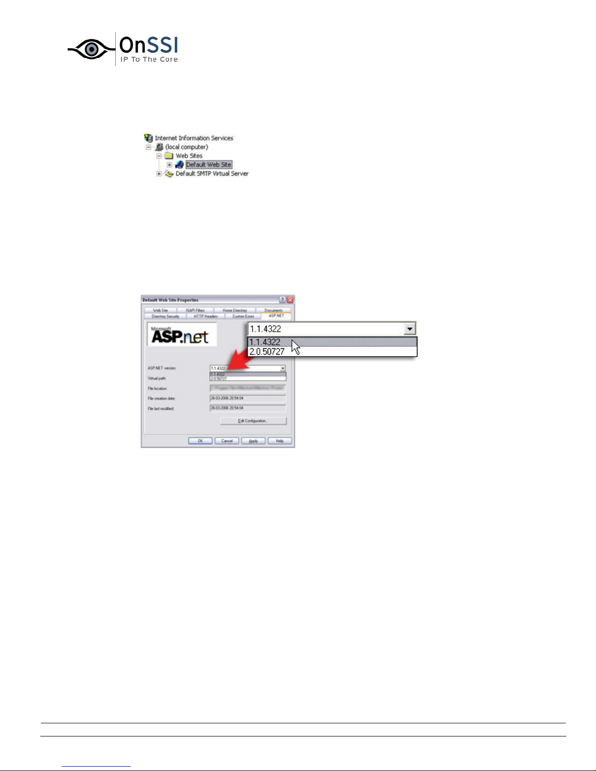
OnSSI NetDVMS Rev 6.5
System Requirements
4. In the Internet Information Services window's left pane, locate and right-click the Default
Web Site item:
Example only; content on
your server may be different
5. In the resulting menu, select Properties. This will open the Default Web Site Properties
dialog.
6. Select the dialog's ASP.NET tab.
The .Net Framework in use will be indicated in the ASP.NET version field.
7. If required, change the ASP.NET version to 1.1.4322:
Example only.
8. Click OK.
9. Close the Internet Information Services and Administrative Tools windows if still open.
On-Net Surveillance Systems, Inc. | 222 Route 59, Suite 303, Suffern, NY 10901 | T: 845-369-6400 | F: 845-369-8711 | www.onssi.com | [email protected] | page 6
Page 18

• NetPDA/NetCell Client
Operating
System
CPU Intel StrongARM or 100% compatible.
RAM Minimum 32 MB.
Network Ethernet (256 Kbit or higher recommended)
Microsoft Windows Pocket PC 2003/2003 SE/Mobile 5.0.
OnSSI NetDVMS Rev 6.5
System Requirements
Graphics
Minimum 320 x 200, 16 bit colors.
Adapter
Software Microsoft Windows Pocket PC 2003/2003 SE/Mobile 5.0.
• NetMatrix Monitor
Operating
System
CPU Intel Pentium 4, 2.4 GHz or higher.
RAM Minimum 512 Mbyte (1 GB recommended on Microsoft
Network Ethernet (100 Mbit or higher recommended).
Graphics
Adapter
Hard Disk
Space
Software DirectX 9.0 or newer
* Running as a 32 bit service/application.
Tip: To check which DirectX version is installed on a computer, click Start, select
Run..., and type dxdiag. When you click OK, the DirectX Diagnostic Tool window will
open; version information is displayed near the bottom of its System tab. Should the
server require a DirectX update, the latest versions of DirectX are available from
http://www.microsoft.com/downloads/
Microsoft Windows XP Professional (32 bit or 64 bit*) and
Windows Server 2003 (32 bit or 64 bit*), Windows Vista
Business (32 bit or 64 bit*), Windows Vista Enterprise (32 bit
or 64 bit*) and Windows Vista Ultimate (32 bit or 64 bit*).
Windows Vista).
AAGP or PCI-Express, minimum 1024 x 768, 16 bit colors.
Minimum 50 Mbyte free.
.
On-Net Surveillance Systems, Inc. | 222 Route 59, Suite 303, Suffern, NY 10901 | T: 845-369-6400 | F: 845-369-8711 | www.onssi.com | [email protected] | page 7
Page 19

OnSSI NetDVMS Rev 6.5
System Requirements
Important Port Numbers
NetDVMS uses particular ports when communicating with other computers, cameras, etc.
What is a port? A port is a logical endpoi n t for data traffic. Networks use different ports for different
types of data traffic. Therefore it is sometimes, but not always, necessary to specify which port to use for
particular data communication. Most ports are used automatically based on the types of data included in
the communication. On TCP/IP networks, port numbers range from 0 to 65536, but only ports 0 to 1024
are reserved for particular purposes. For example, port 80 is used for HTTP traffic which is used when
viewing web pages.
When using NetDVMS, make sure that the following ports are open for data traffic on your network:
• Port 20 and 21 (inbound and outbound): Used for FTP traffic. FTP (File Transfer Protocol) is a
standard for exchanging files across networks. FTP uses the TCP/IP standards for data transfer,
and is often used for uploading or downloading files to and from servers.
• Port 25 (inbound and outbound): Used for SMTP traffic. SMTP (Simple Mail Transfer Protocol) is a
standard for sending e-mail messages between servers. This port should be open since,
depending on configuration, some cameras may send images to the surveillance system server
via e-mail.
• Port 80 (inbound and outbound): Used for HTTP traffic between the surveillance server and
cameras, NetGuards and/or NetGuard-EVSs, and the default communication port for the
surveillance system's Image Server. HTTP (HyperText Transfer Protocol) is a standard for
exchanging files across networks; widely used for formatting and transmission of data on the
world wide web.
• Port 1024 and above (outbound only): Used for HTTP traffic between cameras and the
surveillance server.
• Any other port numbers you may have selected to use, for example if you have changed the
traffic.
Image Server's port from its default port number (80) to another port number.
Tip: Consult the administrator of your organization's firewall if in doubt about how to open ports for
Windows Vista Information
If you wish to install, configure and run NetDVMS on a Windows Vista computer, it is very important that
you have administrator rights. If you only have standard user rights, you will not be able to configure the
software or stop and start the Recording Server service. However, you are still able to view live and
recorded video via the NetGuard-EVS.
These restrictions are a part of the User Account Control, a security component in Windows Vista. Note,
however, that it is possible to disable the User Account Control. For more information visit
www.microsoft.com, and search for Vista User Account Control or similar.
On-Net Surveillance Systems, Inc. | 222 Route 59, Suite 303, Suffern, NY 10901 | T: 845-369-6400 | F: 845-369-8711 | www.onssi.com | [email protected] | page 8
Page 20
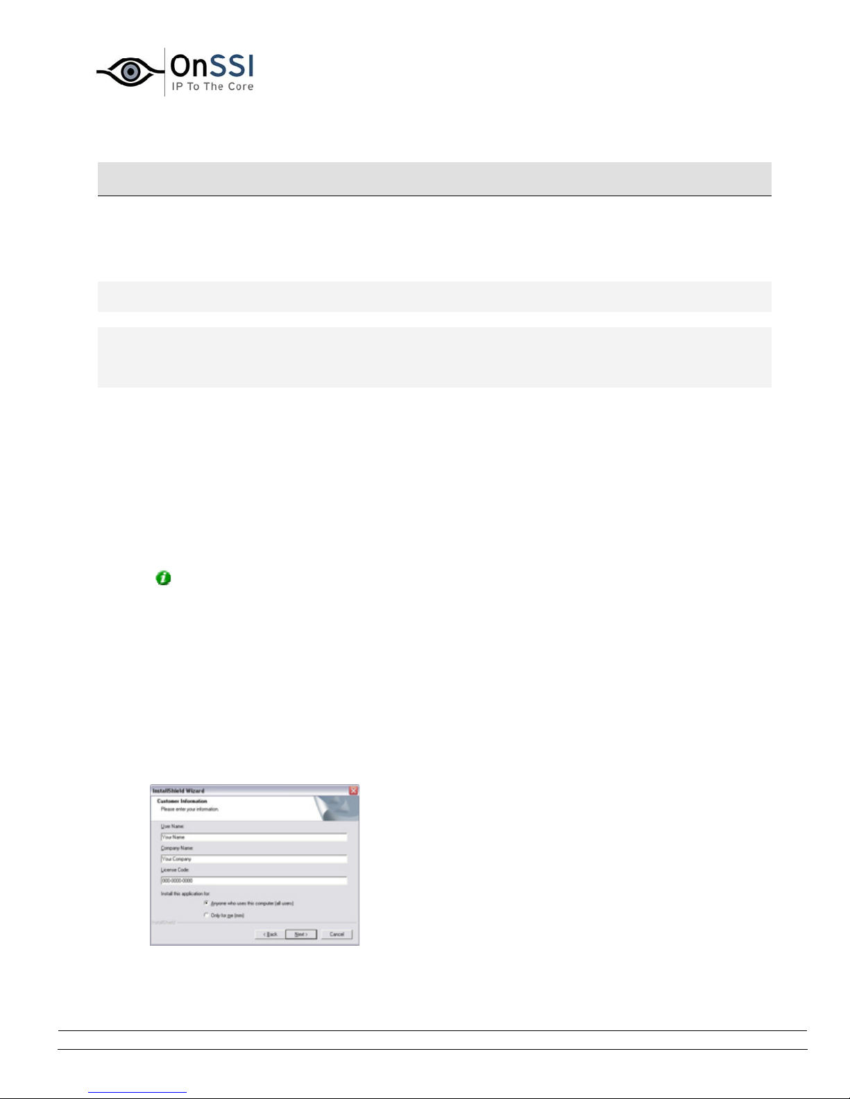
OnSSI NetDVMS Rev 6.5
Installation
Installation
Installing the Software
Note: Read the End User License Agreement on the Product License Sheet (enclosed with the software
CD) before installing NetDVMS.
Note: Do not install NetDVMS on a mounted drive (i.e. a drive attached to an empty folder on an NTFS
(NT File System) volume, with a label or name instead of a drive letter). If using mounted drives, critical
system features may not work as intended; you will, for example, not receive any warnings if the system
runs out of disk space.
To install NetDVMS, do the following:
Prerequisites: Shut down any existing OnSSI software running. If upgrading, it is highly recommended
that you remove any previous versions before upgrading.
1. Insert the NetDVMS software CD, wait for a short while, select required language, then click the
Install NetDVMS link.
Alternatively, if you are installing a version downloaded from the internet, run the file
NetDVMS.exe from the location you have saved it to.
Tip: Depending on your security settings, you may receive one or more security warnings (Do
you want to run or save this file?, Do you want to run this software?). When this is the case,
click the Run button.
2. When the installation wizard starts, click Next to continue the installation.
3. Read and accept the End User License Agreement.
4. Select required language version, and click Next.
5. Select the Licensed Version option, and click Next.
6. Type your Software License Code, as listed on your Product License Sheet.
You have the option of installing the software for anyone using the computer, or for yourself only.
On-Net Surveillance Systems, Inc. | 222 Route 59, Suite 303, Suffern, NY 10901 | T: 845-369-6400 | F: 845-369-8711 | www.onssi.com | [email protected] | page 9
Page 21

OnSSI NetDVMS Rev 6.5
Installation
If in doubt, select Anyone ...
Tip: If installing for yourself only, bear in mind that if your login is not an administrator login,
you will need to change the login name for the Image Server service so it matches your own login,
i.e. uses the same user name and password.
When ready, click Next.
7. Select required language for the NetGuard, one of NetDVMS's remote access clients.
Tip: You do not have to select a language version for the NetGuard-EVS during installation; the
NetGuard-EVS automatically comes with several languages, and users select their individual
language versions themselves.
When ready, click Next.
8. Follow the next few simple steps in the installation wizard until you are asked to select the setup
type that best suits your needs:
• If you want shortcuts to NetDVMS's various applications placed on the desktop
automatically, keep Add shortcut to desktop check box selected.
When ready, click Next.
9. Click Finish on the last step to complete the installation.
When the installation of NetDVMS has finished, the installation of the NetGuard-EVS will automatically
start. Follow the steps until the installation is finished.
Note: If the Administrator window appears on your screen during the installation simply close it by
clicking the Exit button.
Tip: For descriptions of how to install NetDVMS's various remote access clients, see information about
each individual client. A good starting point is the Remote Access Overview. Installation of the NetMatrix
Monitor software is covered in Installing the NetMatrix Monitor Software
.
On-Net Surveillance Systems, Inc. | 222 Route 59, Suite 303, Suffern, NY 10901 | T: 845-369-6400 | F: 845-369-8711 | www.onssi.com | [email protected] | page 10
Page 22
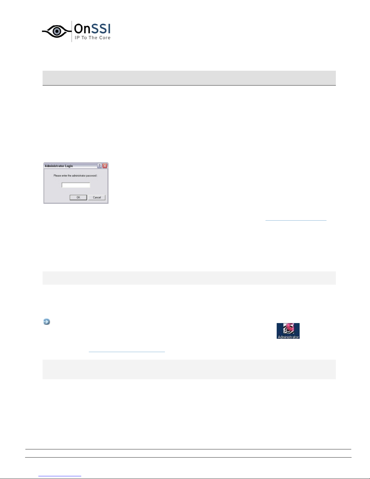
OnSSI NetDVMS Rev 6.5
Administration
Administration
Administrator Login Window
For users without administrator rights, access to certain features in NetDVMS may in some organizations
have been restricted.
When this is the case, you will be asked to specify the administrator password in the Administrator Login
window in order to get access to the restricted features.
The Administrator Login window
You will only be asked to specify the administrator password when you open the Administrator application,
by selecting it from Windows' Start menu or by clicking the Administrator shortcut on the desktop. This
will only be the case when access to the Administrator application has been password-protected.
Administrator Window
Note: Access to features in the Administrator application, including those described in the following, may
require administrator rights.
The Administrator window, the main window in the Administrator application, is used by the surveillance
system administrator for configuring NetDVMS upon installation or whenever configuration adjustments
are required, e.g. when adding new cameras to the system.
Access: You access the Administrator application by selecting it from
Window's Start menu or by clicking the Administrator shortcut on the
desktop.. Access to the Administrator application may be password
protected, in which case you will be asked to provide the administrator
password in the Administrator Login window
IMPORTANT: Changes you make in the Administrator application are not applied on your surveillance
system until you exit the Administrator application. This allows you to try out various settings before
making them take effect.
The Administrator window features a Device Manager section as well as a number of buttons providing
access to configuration:
.
Administrator
desktop shortcut
On-Net Surveillance Systems, Inc. | 222 Route 59, Suite 303, Suffern, NY 10901 | T: 845-369-6400 | F: 845-369-8711 | www.onssi.com | [email protected] | page 11
Page 23
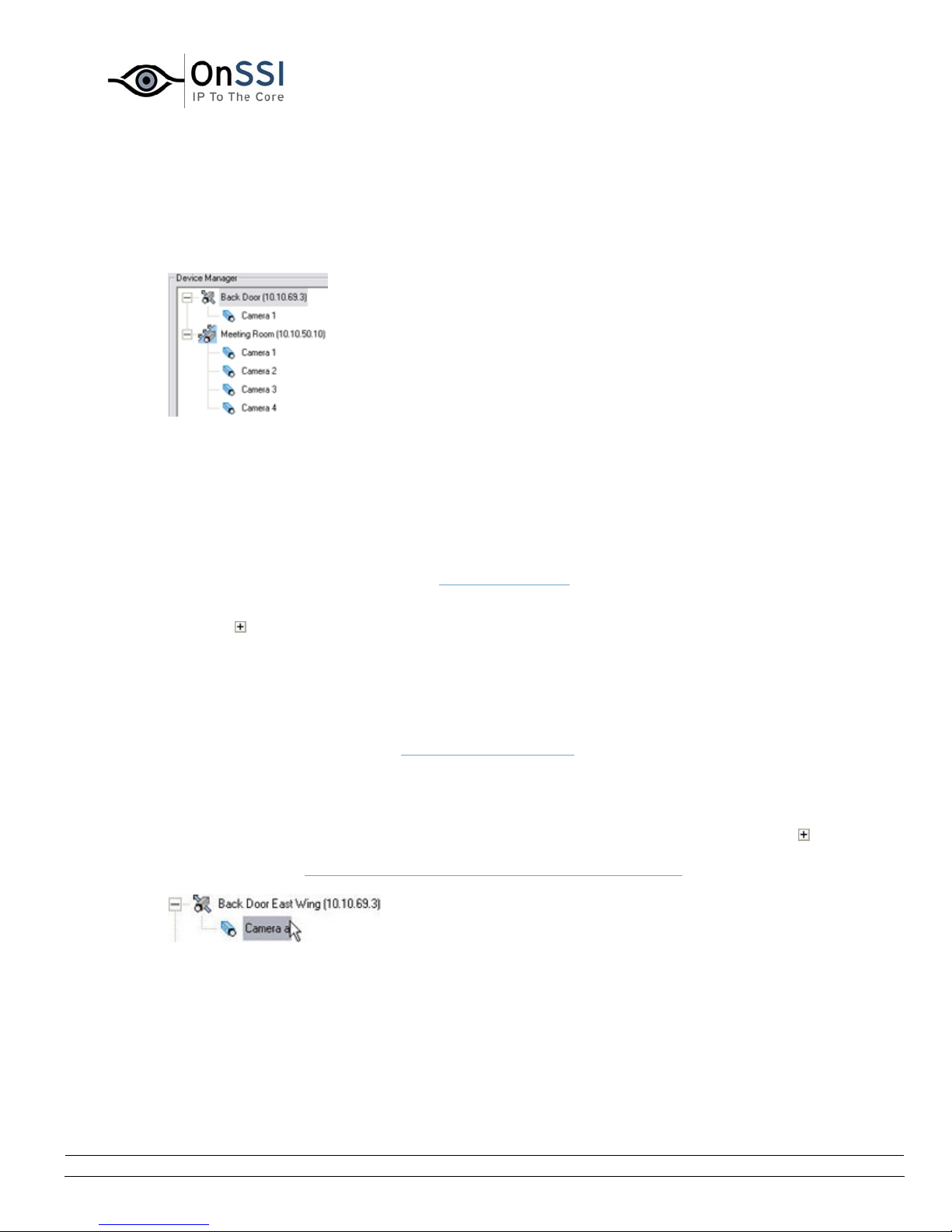
OnSSI NetDVMS Rev 6.5
Administration
• Device Manager Section
The Device Manager section—located in the middle of the Administrator window—lists all added
devices and attached cameras. The Device Manager section thus provides you with an overview
of your surveillance system.
Detail from the Administrator window's Device Manager section—two
devices have been added; the first device has a single camera
attached, whereas the second device has four cameras attached
Until you have added devices, the Device Manager section will be empty.
Adding Devices
You add devices through an intuitive Device Setup Wizard, available by clicking the Administrator
window’s Add Device button (see also
How to Add a Device).
When devices have been added, they will be listed in the Device Manager section. Clicking the
plus sign next to a device in the Device Manager section will list cameras attached to the
device.
Editing Settings for Devices
To edit settings for a device listed in the Device Manager section, select the device, then click the
Edit device... button to open the Edit device settings window.
Editing Settings for Cameras
To edit the settings for a camera listed in the Device Manager section, click the plus sign next
to the device to which the camera is attached, select the required camera, then click the Settings
button to open the
Camera Settings for [Device name] [Camera Name] window.
On-Net Surveillance Systems, Inc. | 222 Route 59, Suite 303, Suffern, NY 10901 | T: 845-369-6400 | F: 845-369-8711 | www.onssi.com | [email protected] | page 12
Page 24
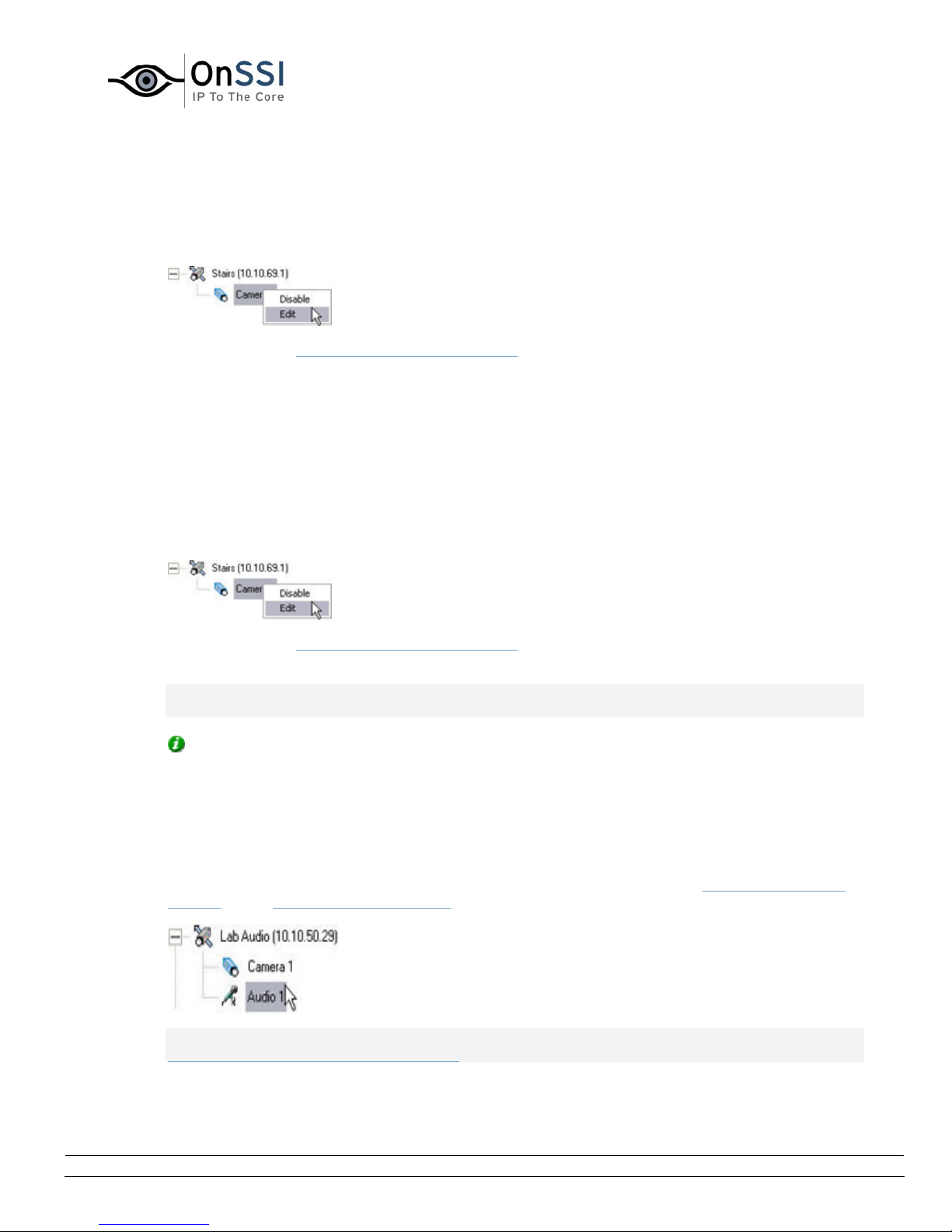
OnSSI NetDVMS Rev 6.5
Administration
Renaming a Camera
To rename a camera, right-click the camera name in question, then select Edit from the menu
that appears:
This will open the Camera Name and Number window, in which you are able to overwrite the existing
camera name with a new one.
Assigning Shortcut Numbers to Cameras
Users of the scname can take advantage of a range of keyboard shortcuts, some of which let the
users toggle between viewing different cameras. Such keyboard shortcuts include numbers, which
are used to identify each camera. These camera shortcut numbers are specified in the
Administrator.
To assign a shortcut number to a camera, right-click the camera name in question, then select
Edit from the menu that appears:
This will open the Camera Name and Number window, in which you are able to specify a shortcut
number to be used with the camera.
Note: Camera shortcut numbers are only used in the scname. In other applications, such as the
NetGuard, the camera shortcuts cannot be used.
Tip: More information about using keyboard shortcuts in the scname is available in Using
Standard Keyboard Shortcuts (described in the NetGuard-EVS's User Manual).
Editing Settings for Audio Sources
To edit the settings for an audio source (that is a microphone or a speaker) listed in the Device
Manager section, click the plus sign next to the device to which the audio source is attached,
select the required audio source, then click the Settings button to open the Microphone Settings
window or the Speaker Settings window.
IMPORTANT: The use of microphones will impact the database capacity for storing video; see
Important Information about Using Audio for more information.
On-Net Surveillance Systems, Inc. | 222 Route 59, Suite 303, Suffern, NY 10901 | T: 845-369-6400 | F: 845-369-8711 | www.onssi.com | [email protected] | page 13
Page 25
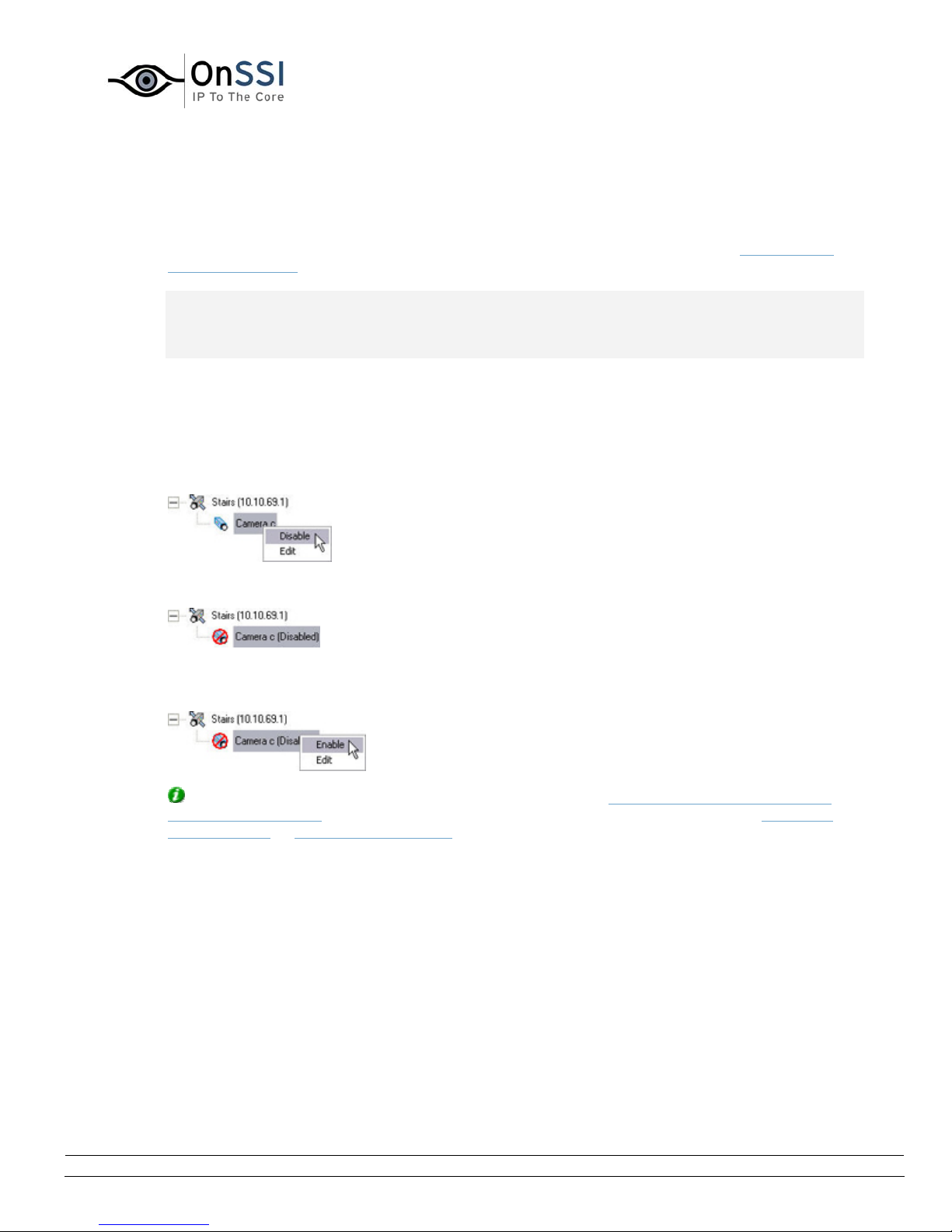
OnSSI NetDVMS Rev 6.5
Administration
Disabling/Enabling Cameras and Audio Sources
Individual cameras and audio sources listed in the Device Manager section are by default
disabled, meaning that video from cameras and audio from attached microphones is by default
transferred to NetDVMS—provided that the cameras are marked as online in the Camera/Alert
Scheduler Window (also default).
Note: On some devices, audio can also be enabled/disabled on the device itself, typically through
the device's own configuration web page. If audio on a device does not work after enabling it in
the Administrator application, you should thus verify whether the problem may be due to audio
being disabled on the device itself.
If required, you can disable individual cameras and audio sources listed in the Device Manager
section. When a camera or audio source is disabled, no images/audio will be transferred from the
camera/audio source to NetDVMS.
To disable a camera or audio source, right-click the required camera or audio source in the Device
Manager section, then select Disable:
When a camera or audio source is disabled, it will be indicated as follows:
To enable a previously disabled camera or audio source, simply right-click the required camera or
audio source in the Device Manager section, then select Enable:
Tip: Individual cameras can also be disabled/enabled in the Camera Settings for [Device Name]
[Camera Name] Window. Individual audio sources can also be disabled/enabled in the Microphone
Settings window or Speaker Settings window respectively.
On-Net Surveillance Systems, Inc. | 222 Route 59, Suite 303, Suffern, NY 10901 | T: 845-369-6400 | F: 845-369-8711 | www.onssi.com | [email protected] | page 14
Page 26
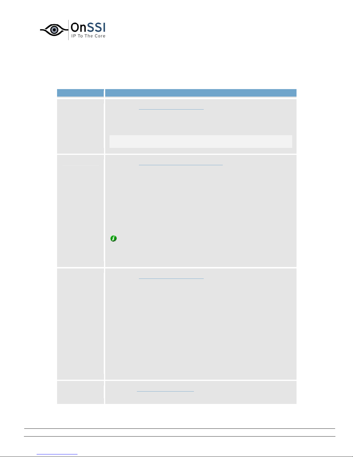
• Administrator Window's Buttons
The Administrator window features the following buttons:
Button Description
OnSSI NetDVMS Rev 6.5
Administration
Service
Manager...
Scheduler... Opens the Camera/Alert Scheduler window, in which you specify
Opens the Service Manager window, which lets you pause/resume
theRecording Server service. Pausing the service is necessary in
order to access some features, for example configuration of PTZ
(Pan/Tilt/Zoom) cameras.
IMPORTANT: While the service is paused, no video or audio will be
recorded.
online periods for each camera.
You are also able to specify if cameras should go online when
specific events occur (e.g. when a door is opened), and if e-mail or
sound alerts should be used if motion is detected during specific
periods of time (e.g. during working hours).
If using PTZ cameras with patrolling, you are furthermore able to
specify if certain patrol schemes should be used during specific
periods of time.
Tip: By default, all cameras are online at all times. You will only
need to modify scheduler settings if you require cameras to be
online only at specific times or events, or if you want to use specific
alerts or PTZ patrol schemes.
General
Settings...
Opens the General Settings window, in which you are able to specify
a number of settings related to:
• Administrator password
• User rights for the Administrator application
• NetCentral settings (if using the NetCentral centralized
monitoring solution in connection with NetDVMS)
• PTZ patrolling pause time out (if using PTZ cameras with
patrolling)
• E-mail settings (for alerts sent via e-mail)
• SMS settings (for alerts sent via SMS)
• Log file settings
• Other advanced settings
Archive
Setup...
On-Net Surveillance Systems, Inc. | 222 Route 59, Suite 303, Suffern, NY 10901 | T: 845-369-6400 | F: 845-369-8711 | www.onssi.com | [email protected] | page 15
Opens theArchive setup window, in which you specify NetDVMS's
archiving settings.
Page 27
OnSSI NetDVMS Rev 6.5
Archiving lets you keep recordings for as long as required, limited
only be the available hardware storage capacity.
Administration
Import
DLKs...
Lets you import all required Device License Keys (DLKs) in one go,
thus avoiding the need to specify each DLK manually when adding
devices.
See also How to Import Device License Keys.
NetMatrix... Lets you access NetMatrix configuration. NetMatrix is an integrated
product for forcing video from any camera to any monitor on a
network operating with NetDVMS.
trname... Note: The trname button is not functional. If trname (add-on
product for handling loss prevention through video evidence
combined with time-linked POS or ATM transaction data) is installed
on the server, use Windows' Start menu or the trname Administrator
desktop shortcut to access the trname Administrator. Use with
trname versions earlier than 2.1 is not supported.
Add
Device...
Starts the Device Setup Wizard, which guides you through the
process of adding a new device.
See also How to Add a Device.
Edit
Device...
When you have selected a device in the Administrator window's
Device Manager section, clicking the Edit Device... button lets you
edit settings for the selected device in the Edit device settings
window.
Remove
Device
Lets you remove a device selected in the Administrator window's
Device Manager section.
In order to prevent accidental removal of devices, you will be asked
to confirm that you want to remove the device.
Settings... Lets you specify settings for a selected camera or audio source:
On-Net Surveillance Systems, Inc. | 222 Route 59, Suite 303, Suffern, NY 10901 | T: 845-369-6400 | F: 845-369-8711 | www.onssi.com | [email protected] | page 16
• Cameras: When you have selected a camera in the
Administrator window's Device Manager section, clicking the
Settings button will open the Camera Settings for [Device
Name] [Camera Name]... window, in which you specify
camera settings.
• Audio sources: When you have selected an audio source in
the Administrator window's Device Manager section, clicking
Page 28
OnSSI NetDVMS Rev 6.5
Administration
the Settings button will open the Microphone Settings
window (if the selected audio source is a microphone) or
Speaker Settings window (if the selected source is a
speaker), in which you can enable/disable the audio source
and change its name if required.
I/O Setup... Opens the I/O Setup window, in which you are able to define events
based on input events (for example when a door sensor detects that
a door is opened) and VMD (Video Motion Detection). The I/O Setup
window also lets you specify output (e.g. a siren).
When defined, events can be used for a variety of purposes. For
example, an input event can be used for triggering output, for
starting a particular camera, and for triggering that an e-mail or
SMS message is sent to a particular user, notifying the user of the
recorded event.
See also the description of the I/O Control... button.
Event
Buttons...
Opens the Event Buttons window, in which you are able to define
events for use on event buttons.
Event buttons can used in the NetGuard-EVS for manually triggering
events.
Generic
Events...
Opens the Generic Events window, in which you are able to define
events based on input from external sources using the TCP and UDP
protocols.
I/O
Control...
Opens the I/O Control window, in which you are able to attach
outputs to input events.
This way you can, for example, define that a siren should sound
when a sensor detects that a door is opened.
Exit Closes the Administrator application.
Tip: Clicking the icon in the left corner of the Administrator window's title bar, gives you access
to a small menu. Selecting About Adm ... from the menu will display a dialog with your system's
version number and software license code; this is valuable information, should you ever need to
contact product support.
On-Net Surveillance Systems, Inc. | 222 Route 59, Suite 303, Suffern, NY 10901 | T: 845-369-6400 | F: 845-369-8711 | www.onssi.com | [email protected] | page 17
Page 29

OnSSI NetDVMS Rev 6.5
Administration
Import of DLKs
How to Import Device License Keys
Note: Access to features in the Administrator application, including those described in the following, may
require administrator rights.
You must have a Device License Key (DLK) for every device (IP network camera or IP video server)
installed on your NetDVMS surveillance system.
Remember that you are allowed to install and use only the number of cameras listed on your
organization's license sheet; regardless of you number of available DLKs. For example, a fully used fourport video encoder counts as four cameras even though the cameras are connected through a single
device—therefore a fully used four-port video encoder will use four licenses.
System administrators obtain DLKs as part of the software registration process.
You are able to specify each DLK manually when
available by clicking the Add Device... button in the
to specify each DLK manually by using the following procedure to import all received DLKs into NetDVMS
in one go:
Prerequisites: The DLKs, received in a .dlk file, must have been saved at a location accessible by the
surveillance server, for example on a network drive or on a USB stick.
1. Open the
Administrator window.
2. In the Administrator window, click the Import DLKs... button.
3. Browse to the location at which you have saved the received .dlk file.
Select the file, and click Open.
All DLKs are now automatically imported, and the relevant DLK will automatically appear when
you
add a device through the Device Setup Wizard.
adding a device through the Device Setup Wizard,
Administrator window. However, you can avoid having
On-Net Surveillance Systems, Inc. | 222 Route 59, Suite 303, Suffern, NY 10901 | T: 845-369-6400 | F: 845-369-8711 | www.onssi.com | [email protected] | page 18
Page 30
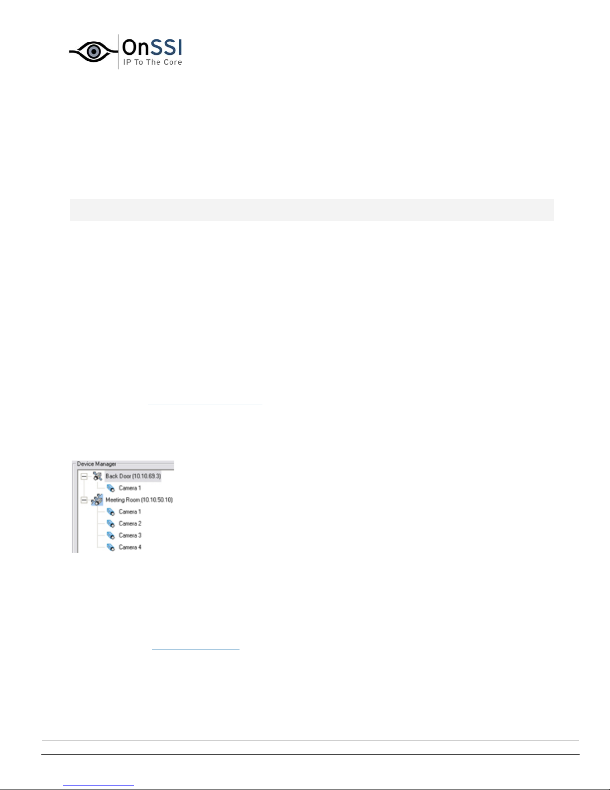
OnSSI NetDVMS Rev 6.5
Administration
Device Administration
How to Add a Device
Note: Access to features in the Administrator application, including those described in the following, may
require administrator rights.
In NetDVMS you add devices (IP video camera devices, IP video encoder devices or digital video recorder
devices (DVR devices)) rather than actual cameras. This is because devices have their own IP addresses
or host names. Being IP-based, NetDVMS primarily identifies units on the surveillance system based on
their IP addresses or host names.
Even though each device has its own IP address or host name, several cameras can be attached to a
single device and thus share the same IP address or host name. This is typically the case with cameras
attached to video encoder devices or DVR devices.
You can of course configure and use each camera individually, even when several cameras are attached
to a single device.
In addition to IP video camera devices, IP video encoder devices and DVR devices it is possible to add a
number of dedicated I/O (input/output) devices to NetDVMS. When such I/O devices are added, they can
be used in events-based system setup in the same way as a camera. For more information about using
I/O devices, see
to the release note.
Once a device is added in NetDVMS, any cameras attached to the device are automatically recognized by
the software, and listed in the Administrator window's Device Manager section:
Using Dedicated I/O Devices. For information about which I/O devices are supported, refer
Detail from the Administrator window's Device Manager section—two
devices have been added; the first device has a single camera
attached, whereas the second device has four cameras attached
To add a device, use the following procedure:
Prerequisites: You must have configured IP address, password, etc. on the device itself, as described by
the manufacturer.
1. Open the
Administrator window.
2. In the Administrator window, click the Add Device... button. This will start the Device Setup
Wizard.
On-Net Surveillance Systems, Inc. | 222 Route 59, Suite 303, Suffern, NY 10901 | T: 845-369-6400 | F: 845-369-8711 | www.onssi.com | [email protected] | page 19
Page 31
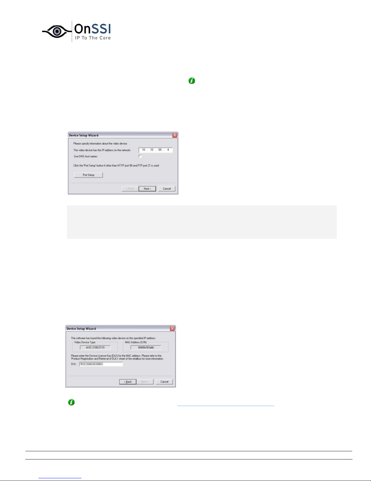
3. On the first step of the wizard, identify the required device, either by
• Typing the IP address of the device. Tip: To jump to the next IP address segment in
the field, press SPACE on your keyboard.
- or -
• Typing the DNS host name of the device. This requires that you select the Use DNS host
names box
OnSSI NetDVMS Rev 6.5
Administration
Specifying the IP address of a device
Note: By default, HTTP port 80 and FTP port 21 will be used for the device. If the device you are
adding uses other port numbers, click the Port Setup button and specify required port numbers.
The need for specifying different ports may often apply if the device is located behind a NATenabled router or a firewall. When this is the case, also remember to configure the
router/firewall so it maps the ports and IP address used by the device.
When ready, click Next to go to the second step of the wizard.
4. If a password is used for the device, type the password for the device's administrator account
(called a ”admin” or ”root” account on some devices).
Leave the Autodetect Device option selected.
Click Next.
5. When the device has been detected, type the Device License Key (DLK) for the device in the DLK
field.
Specifying DLK for the device
Tip: If you have imported DLKs (see How to Import Device License Keys), the DLK field will
already be filled with the DLK for the device.
On-Net Surveillance Systems, Inc. | 222 Route 59, Suite 303, Suffern, NY 10901 | T: 845-369-6400 | F: 845-369-8711 | www.onssi.com | [email protected] | page 20
Page 32
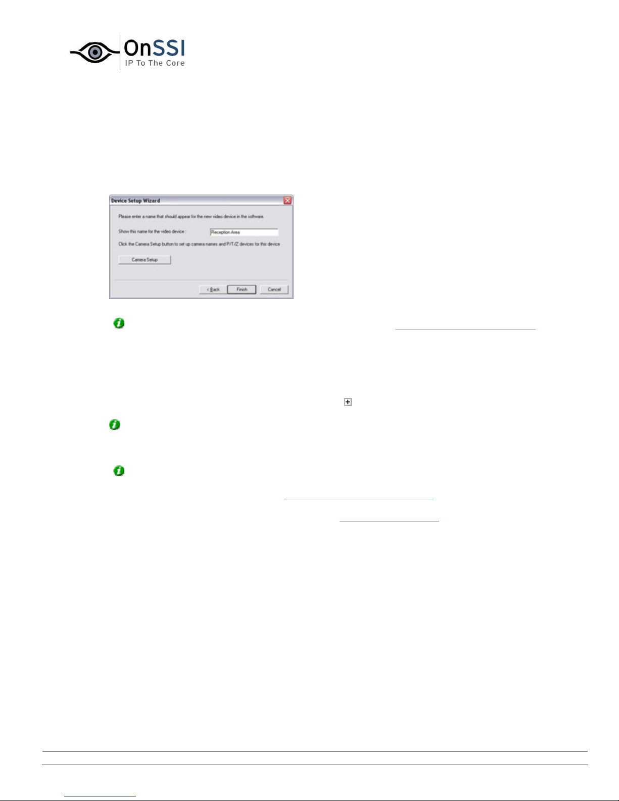
OnSSI NetDVMS Rev 6.5
Administration
Click Next.
6. Assign a unique and descriptive name to the device.
Upon completion of the wizard, the name will be used when listing devices and associated
cameras in the Administrator window's Device Manager section. The name may, for example,
refer to the physical location of the camera(s) attached to the device.
Assigning a name to the device
Tip: You may click the Camera Setup button to access the Camera Settings for … window, in
which you are able to specify certain settings related to camera name and PTZ control. The latter
requires that the camera is a PTZ (Pan/tilt/Zoom) camera.
7. Click Finish.
8. The device will be listed in the Administrator window's Device Manager section. To view a list of
cameras attached to the device, click the plus sign
next to the device name.
Tip: Cameras are listed for each device with default names, such as 'Camera 1,' etc. If you
want to change the name of a camera, right-click the camera name in question, then select Edit
from the menu that appears.
Tip: Individual cameras listed in the Device Manager section are by default enabled, meaning
that images from the cameras are by default transferred to NetDVMS—provided that the
cameras are marked as online in the Camera/Alert Scheduler Wi
ndow (also default). If required,
you can disable a camera listed in the Device Manager section by right-clicking the name of the
camera in question. See more information under Administrator window
.
On-Net Surveillance Systems, Inc. | 222 Route 59, Suite 303, Suffern, NY 10901 | T: 845-369-6400 | F: 845-369-8711 | www.onssi.com | [email protected] | page 21
Page 33
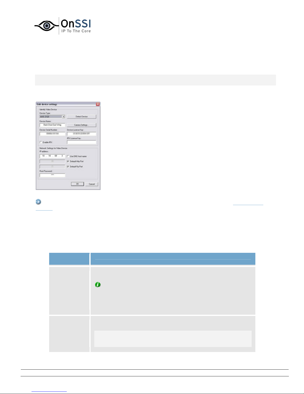
OnSSI NetDVMS Rev 6.5
Administration
Edit Device Settings Window
Note: Access to features in the Administrator application, including those described in the following, may
require administrator rights.
The Edit device settings window lets you edit the settings of an already installed device.
The Edit device settings window
Access: To access the Edit device settings window, select the required device in the Administrator
window's Device Manager section, and click the Edit Device... button.
The Edit device settings window is divided into two sections:
• Identify Video Device Section
The Identify Video Device section contains the following fields, buttons, etc.:
Field,
Button, ...
Device Type Select required device type from list.
Detect
Device
Description
Tip:NetDVMS is able to automatically detect device type as well
as serial number, provided the IP address/hostname and password
of the device have been specified in the IP-address/DNS Host Name
and Root Password fields: Simply click the Detect Device button to
auto-detect device type and serial number.
Click button to auto-detect device type and serial number.
Note: Use of the auto-detect feature requires that the IP address
and password of the device have been specified in the IP-address
and Root Password fields.
On-Net Surveillance Systems, Inc. | 222 Route 59, Suite 303, Suffern, NY 10901 | T: 845-369-6400 | F: 845-369-8711 | www.onssi.com | [email protected] | page 22
Page 34
OnSSI NetDVMS Rev 6.5
Administration
Device
Name
Camera
Settings...
Device
Serial
Number
Name used to identify the device.
Tip: To enable easy identification of devices, it is often a good
idea to use a device name that refers to the physical area covered
by the cameras attached to the device (examples: Reception Area,
Car Park B, Entrance Door, ...).
Note: Device names must be unique; you cannot use the same
name for several devices.
Opens the Camera Settings for [Device Name] window, in which you
are able to specify a number of settings for cameras attached to the
device, including:
• Port through which PTZ (Pan/Tilt/Zoom) cameras are
controlled
• Camera names, types, and ports
Note: The number of settings available in the Camera Settings for
[Device Name] window may be limited if cameras are not PTZ
cameras or connected to a video encoder device.
Serial number of device; usually identical to the 12-character MAC
address of the device (example: 0123456789AF).
Tip:NetDVMS is able to automatically detect serial number as well
as device type, provided the IP address/host name and password of
the device have been specified in the IP-address/DNS Host Name
and Root Password fields: Simply click the Detect Device button to
auto-detect device type and serial number.
Device
License Key
A 16-character license key (DLK) for the device, obtained when
registering the software.
Enable iPIX Enables the use of IPIX, a technology that allows viewing of 360-
degree panoramic images.
Note: Use of the IPIX technology requires either a dedicated IPIX
camera or a regular camera equipped with a special IPIX camera
lens for which a special IPIX license key is required. If the device in
question is for a dedicated IPIX camera, the check box is selected by
default, and you do not have to enter an IPIX license key in the
neighboring field.
iPIX License
Key
License key for using the IPIX technology, obtained when registering
the software.
Note: This information is only required if the Enable iPIX check box
is selected manually.
On-Net Surveillance Systems, Inc. | 222 Route 59, Suite 303, Suffern, NY 10901 | T: 845-369-6400 | F: 845-369-8711 | www.onssi.com | [email protected] | page 23
Page 35

• Network Settings for Video Device Section
The Network Settings for Video Device section contains the following fields:
Field Description
OnSSI NetDVMS Rev 6.5
Administration
IP-address
-or-
DNS Host
Name
Use DNS
host name
Default
Http Port
Default Ftp
Port
IP address or DNS host name of the device in question.
Note: If Use DNS host name check box is selected, the name
of the IP-address field changes to DNS/Host Name in order to
accommodate a DNS host name rather than an IP address.
By selecting the check box you are able to use a DNS host
name for identifying the device instead of using the device's
IP address.
When check box is selected, the IP-address field changes its
name to DNS/Host Name, ready to accommodate a DNS host
name rather than an IP address.
When selected, HTTP traffic to the device will go through the
default port, port 80.
If you want to use another port for HTTP traffic to the device,
clear the check box, and specify required port number in the
field to the left of the check box.
When selected, FTP traffic to the device will go through the
default port, port 21.
If you want to use another port for FTP traffic to the device,
clear the check box, and specify required port number in the
field to the left of the check box.
Root
Password
On-Net Surveillance Systems, Inc. | 222 Route 59, Suite 303, Suffern, NY 10901 | T: 845-369-6400 | F: 845-369-8711 | www.onssi.com | [email protected] | page 24
Password required in order to log in to the device using the
root account (occasionally known as an admin or
administrator account).
Page 36
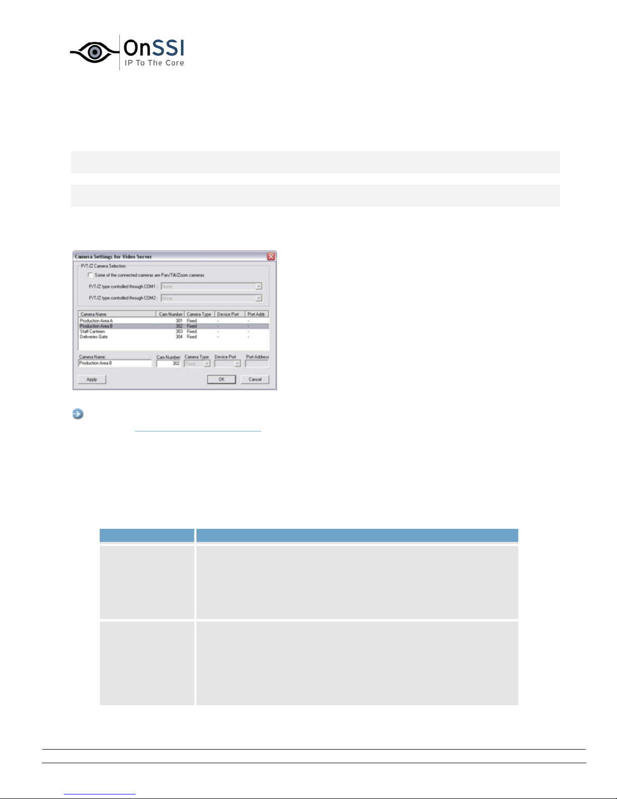
OnSSI NetDVMS Rev 6.5
Administration
Camera Settings for [Device Name] Window
Note: Access to features in the Administrator application, including those described in the following, may
require administrator rights.
Note: The number of settings available in the Camera Settings for [Device Name] window may be limited
if cameras are not PTZ (Pan/Tilt/Zoom) cameras or connected to a video encoder device.
The Camera Settings for [Device Name] window lets you specify certain information about a device's
cameras. This is primarily interesting for PTZ cameras and cameras attached to a video encoder device.
The Camera Settings for [Device Name] window
Access: You access the Camera Settings for [Device Name] window by clicking the Camera Settings...
button in the Edit device settings window.
The Camera Settings for [Device Name] window is divided into a P/T/Z Camera Selection section and a
camera list:
• P/T/Z Camera Selection Section
The P/T/Z Camera selection section contains the following fields:
Field Description
Some of the
connected
cameras are
Pan/Tilt/Zoom
cameras
P/T/Z type
controlled
through COM1
Select check box if any of the cameras attached to the video
encoder device is a PTZ camera.
If the check box is not available, PTZ is not supported for the
device in question.
Field available only if Some of the connected cameras are
Pan/Tilt/Zoom cameras check box is selected.
If a PTZ camera is controlled through the COM1 port on the video
encoder device, select the required PTZ camera type from the list.
On-Net Surveillance Systems, Inc. | 222 Route 59, Suite 303, Suffern, NY 10901 | T: 845-369-6400 | F: 845-369-8711 | www.onssi.com | [email protected] | page 25
Page 37
OnSSI NetDVMS Rev 6.5
If no PTZ cameras are controlled through the COM1 port, select
None.
Administration
P/T/Z type
controlled
through COM2
Field available only if Some of the connected cameras are
Pan/Tilt/Zoom cameras check box is selected.
If a PTZ camera is controlled through the COM2 port on the video
encoder device, select the required PTZ camera type from the list.
If no PTZ cameras are controlled through the COM2 port, select
None.
• Camera List and Fields
The camera list contains a line for each camera channel on the device. First line from the top
corresponds to camera channel 1, second line from the top corresponds to camera channel 2, etc.
To change camera settings, select the required camera channel from the list, specify required
information in the following fields, and click the Apply button:
Field Description
Camera
Name
Name used to identify the selected camera.
Existing names, such as the default camera names Camera 1,
Camera 2, etc. can be changed by overwriting the existing names.
Note: Camera names must be unique for each device.
Cam
Number
Users of the NetGuard-EVS can take advantage of a range of
keyboard shortcuts, some of which let the users toggle between
viewing different cameras. Such shortcuts include numbers, which
are used to identify each camera. Each camera's shortcut number is
specified in the Cam Number field.
A camera shortcut number must not contain any letters or special
characters, and must be no longer than eight digits. Examples of
correct camera shortcut numbers: 3, 12345678. Examples of
incorrect camera shortcut numbers: A*3, 123456789.
It is highly recommended that you use a unique camera shortcut
number for each camera.
Note: Camera shortcut numbers are only used in the NetGuard-EVS.
In other applications, such as the NetGuard, the camera shortcuts
cannot be used.
Tip: You can also assign shortcut numbers to cameras in the
Camera Name and Number window.
On-Net Surveillance Systems, Inc. | 222 Route 59, Suite 303, Suffern, NY 10901 | T: 845-369-6400 | F: 845-369-8711 | www.onssi.com | [email protected] | page 26
Page 38
OnSSI NetDVMS Rev 6.5
Tip: More information about using keyboard shortcuts in the
scname is available in Using Standard Keyboard Shortcuts.
Administration
Camera
Type
Lets you select whether the camera on the selected camera channel
is Fixed or Moveable:
• Fixed: Camera mounted in a fixed position
• Moveable: PTZ camera
Device Port Available only if Moveable is selected in the Camera Type field.
Lets you select which control port on the video encoder should be
used for controlling PTZ functionality on the camera.
Port
Address
Available only if Moveable is selected in the Camera Type field.
Lets you specify port address of the camera.
The port address would normally be 0 or 1. If using daisy chained
PTZ cameras, the port address will identify each of them, and you
should verify your settings with those recommended in the cameras'
manuals.
Using DVR Devices
You can easily use DVR (Digital Video Recorder) devices with your NetDVMS application. A DVR device is
added like any other device.
The user of NetGuard-EVS will experience no difference from viewing video from a camera attached to at
DVR than viewing video from any other camera. When the user views recordings, the recordings will be
viewed from the DVRs own hard disk instead of a database in your NetDVMS application.
As an administrator you will notice that a DVR device is displayed the same way in the Administrator
window as a video encoder. However, the use of PTZ cameras is not supported by DVR devices.
On-Net Surveillance Systems, Inc. | 222 Route 59, Suite 303, Suffern, NY 10901 | T: 845-369-6400 | F: 845-369-8711 | www.onssi.com | [email protected] | page 27
Page 39

OnSSI NetDVMS Rev 6.5
Administration
Camera Administration
About Camera Administration ...
Note: Access to features in the Administrator application, including those described in the following, may
require administrator rights.
Adding Cameras
In NetDVMS you do not have to worry about having to add individual cameras to the system:
Cameras are connected to devices, so once you have added the required devices to your NetDVMS
system (see
well.
How to Add a Device), all cameras connected to the devices are connected to the system as
Configuring Cameras
You are able to specify a wide variety of settings for each camera connected to the NetDVMS system.
Your entry point for such camera configuration is the
To configure a camera, select the required camera in the Administrator window's Device Manager section,
then click the Administrator window's Settings... button.
This will open the
settings for the camera in question, including:
Camera Settings for [Device Name] [Camera Name] window, in which you have access to
• How the camera should record (frame rate, image quality, etc.)
• Where and when to store recorded images from the camera
• Motion detection sensitivity
• Triggering of notifications and external output
• ... and more
This also applies if you want to edit the settings for an already configured camera.
Administrator window.
On-Net Surveillance Systems, Inc. | 222 Route 59, Suite 303, Suffern, NY 10901 | T: 845-369-6400 | F: 845-369-8711 | www.onssi.com | [email protected] | page 28
Page 40
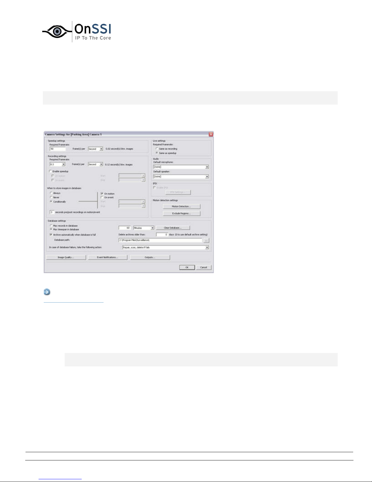
OnSSI NetDVMS Rev 6.5
Administration
Camera Settings for [Device Name] [Camera Name] Window
Note: Access to features in the Administrator application, including those described in the following, may
require administrator rights.
The Camera Settings for [Device Name] [Camera Name] window lets you specify settings for a particular
camera.
Example: The Camera Settings for [Device Name]
[Camera Name] window for a PTZ camera
Access: You access the Camera Settings for [Device Name] [Camera Name] window from the
Administrator window
, by selecting a camera in the Device Manager section, then clicking the Settings...
button.
The Camera Settings for [Device Name] [Camera Name] window contains the following sections and
buttons:
• Speedup Settings
Note: Special settings apply for cameras using MPEG. Read more at the end of the description of
this section.
The Speedup Settings section lets you specify the required number of frames to be used when
motion is detected and/or an event occurs in this field.
• Required framerate: Specify required number of frames in the first field, and select
required unit (per Second, per Minute, or per Hour) from the list.
The frame rate must be higher than the frame rate specified in the Required framerate field in the
Recording settings section which is described in the following.
On-Net Surveillance Systems, Inc. | 222 Route 59, Suite 303, Suffern, NY 10901 | T: 845-369-6400 | F: 845-369-8711 | www.onssi.com | [email protected] | page 29
Page 41

OnSSI NetDVMS Rev 6.5
Administration
Tip: When you specify a frame rate, the interval between images is automatically calculated
and displayed to the right of the frame rate fields.
Specifically for cameras using MPEG
For MPEG cameras you can select predefined frame rates, and it is not possible to select unit. The
number of seconds between each image is still calculated.
• Recording Settings
Note: Special settings apply for cameras using MPEG. Read more at the end of the description of
this section.
The Recording Settings section lets you specify the camera's recording settings in the following
fields:
• Required framerate: Specify required number of frames in the first field, and select
required unit (per Second, per Minute, or per Hour) from the list.
Tip: When you specify a frame rate, the interval between images is automatically
calculated and displayed to the right of the frame rate fields.
• Enable speedup: NetDVMS is able to increase the frame rate of a camera if motion is
detected, or if an event occurs.
Select the check box to enable increased frame rate on motion detection or on an event,
then specify the required conditions in the following fields.
Tip: In the Camera/Alert Scheduler window you can specify periods in which the
camera should always speedup.
o On motion: Available only if the Enable speedup check box is selected.
Select this check box to use a higher frame rate when motion is detected.
Remember to specify the required higher frame rate in the Speedup settings
section.
The camera will return to the original frame rate two seconds after the last
motion is detected.
o On event:Available only if the Enable speedupcheck box is selected.
Select the check box to use a higher frame rate when an event occurs and until
another event occurs, then select required start and stop events in the Start
and Stop lists.
The camera will increase its frame rate when the start event occurs, and return
to the original frame rate when the stop event occurs.
Remember to specify the required higher frame rate in the Speedup settings
section.
On-Net Surveillance Systems, Inc. | 222 Route 59, Suite 303, Suffern, NY 10901 | T: 845-369-6400 | F: 845-369-8711 | www.onssi.com | [email protected] | page 30
Page 42

OnSSI NetDVMS Rev 6.5
Administration
Note: Use of speedup on event requires that events have been defined in the
I/O Setup window, accessed by clicking the I/O Setup... button in the
Administrator window.
• When to store images in the database:Select when images received from the camera
should be stored in the database:
o Always: Always store all received images in the database.
o Never: Never store any received images in the database. Live images will be
displayed, but, since no images are kept in the database, users will not be able to
browse images from the camera.
o Conditionally: Store received images in the database when certain conditions are
met. When you select this option, specify required conditions in the following
fields.
On motion: Available only when the option Conditionally is selected,
i.e. when images received from the camera should be stored in the
database on certain conditions only.
Select the check box to store all images in which motion is detected.
On event: Available only when the option Conditionally is selected, i.e.
when images received from the camera should be stored in the
database on certain conditions only.
Select the check box to store all images, regardless of motion, when an
external event occurs and until another external event occurs, then
select required start and stop events in the Start and Stop lists.
Note: Use of storage on event requires that events have been defined. Read
more about events in About Input, Events & Output ...
[Number of] seconds pre/post recordings on event: Available only when the
option Conditionally is selected, i.e. when images received from the camera
should be stored in the database on certain conditions only.
You are able to store recordings from periods preceding and following detected
motion and/or specified events. Using such a pre/post buffer can be
advantageous: If, for example, you have defined that images should be stored
when a door is opened, being able to see what happened immediately prior to
the door being opened may be important.
Specify the number of seconds for which you want to store images from before
and after the storage conditions are met.
Example: You have specified that images should be stored conditionally on
event, with a start event called Door Opened and a stop event called Door
Closed. With a pre/post buffer of three seconds, images will be stored from
three seconds before Door Opened occurs to three seconds after Door Closed
occurs.
Note: Pre/post recording periods cannot be displayed in the timelines of the
NetGuard-EVS's timeline browser. The fact that these periods cannot be
displayed in the timeline browser's timelines does not affect recording.
On-Net Surveillance Systems, Inc. | 222 Route 59, Suite 303, Suffern, NY 10901 | T: 845-369-6400 | F: 845-369-8711 | www.onssi.com | [email protected] | page 31
Page 43

OnSSI NetDVMS Rev 6.5
Administration
Specifically for cameras using MPEG
Instead of choosing the required frame rate, you can choose a Frame Type.
Select All to record everything. That is similar to having the same frame rate for speedup and for
recording.
Select Key frame if you wish only to record key frames and ignore changes between the key
frames. That means, that you typically record one frame per second.
• Live Settings
Note: This section is not available for cameras using MPEG. Viewing live video will take place with
the same frame rate as specified for speedup.
The Live settings section lets you specify from where the camera should inherent its frame rate
during live video. Select either Same as recording or Same as speedup.
That means, that when you view live video in one of your access clients e.g. the NetGuard-EVS,
you will always view it either at the frame rate defined for speedup or recording.
• Audio
In the Audio section you are able to associate a microphone and/or a speaker with the selected
camera.
Note: The ability to associate a microphone and/or a speaker with the selected camera requires
that at least one microphone and/or speaker has been attached to a device on the surveillance
system.
When a microphone and/or a speaker is associated with a camera, audio from the source will
automatically be used when images from the camera are viewed. Note that you are able to select
a microphone and/or a speaker attached to another device than the selected camera.
To associate a microphone and/or a speaker with the selected camera, simply select the required
microphone and/or speaker from the Default microphone and Default speaker lists.
For cameras attached to the same device as a microphone and/or a speaker, the microphone
and/or speaker is automatically selected and cannot be changed.
On-Net Surveillance Systems, Inc. | 222 Route 59, Suite 303, Suffern, NY 10901 | T: 845-369-6400 | F: 845-369-8711 | www.onssi.com | [email protected] | page 32
Page 44
OnSSI NetDVMS Rev 6.5
Administration
• IPIX
Note: Functionality in the IPIX section is only available if the use of IPIX technology has been
enabled for the device to which the camera is attached. For dedicated IPIX cameras, the use of
IPIX technology is automatically enabled. If not dealing with a dedicated IPIX camera, you enable
use of IPIX technology for a device in the Edit device settings window, accessed by selecting the
required device in the Administrator window's Device Manager section, then clicking the
Administrator window's Edit Device... button.
The IPIX section contains the following fields and buttons:
• Enable IPIX: Select check box to enable the use of IPIX, a technology that allows viewing
of 360-degree panoramic images through an advanced fish eye lens on the particular
camera.
• IPIX Settings...:Opens the IPIX Camera Configuration window, in which you configure
the camera's IPIX functionality.
• Motion Detection Settings
The Motion Detection Settings section contains two buttons for configuring the camera's motion
detection:
• Motion Detection...:Opens the Adjust Motion Detection window, in which you are able to
specify motion detection sensitivity levels.
• Exclude Regions...:Opens the Define Exclusion Regions window in which you are able to
disable motion detection in specific areas of the camera's images.
Disabling motion detection in certain areas may help you avoid detection of irrelevant
motion, for example if the camera covers an area where a tree is swaying in the wind or
where cars regularly pass by in the background.
• Database Settings
The database for each camera is capable of containing a maximum of 600.000 records or 40 GB
per day.
Note that camera databases also store recorded audio from associated audio sources; see
Important Information about Using Audio
Tip: By using archiving it is possible to store recordings beyond the capabilities of the camera's
database.
The Database settings section lets you specify database settings for the camera, such as where
the database containing the camera's recordings should be kept, how much to store, etc. You
specify this information in the following fields:
for more information.
• Max records in database:Select this option to limit the database size based on a
maximum allowed number of records in the database.
Specify required maximum number of records in the neighboring field.
On-Net Surveillance Systems, Inc. | 222 Route 59, Suite 303, Suffern, NY 10901 | T: 845-369-6400 | F: 845-369-8711 | www.onssi.com | [email protected] | page 33
Page 45

OnSSI NetDVMS Rev 6.5
Administration
When the database reaches the maximum number of records, the oldest record in the
database will automatically be overwritten.
A database can contain up to 600,000 records.
• Max timespan in database: Select this option to limit the database size based on the
age of records in the database.
Specify the required number in neighboring field, and select required unit (Minutes,
Hours, or Days) from the list.
When records become older than the specified number of minutes, hours, or days, they
will automatically be deleted.
Note: A database can contain no more than 600,000 records, regardless of what
maximum age has been defined.
• Clear Database... :Click button to delete all records stored in the database for the
camera in question.
WARNING: Use with caution; all records in the database for the camera will be
permanently deleted. As a security measure, you will be asked to confirm that you want
to permanently delete all stored records for the camera.
Records stored in archived databases will not be affected.
Note: If the Recording Server service is running, the button will not be available. To
make the button available, pause the Recording Server service by clicking the
Administrator window's Service Manager button, then clicking the Pause button or by
stopping the service from the Recording Server Manager icon.
IMPORTANT: No video or audio will be recorded while the Recording Server service is
paused or stopped.
• Archive automatically when database is full: Select this check box if you wish to
automatically archive the database when it is full.
• Delete archives older than [n] days (0 to use default archive setting):In this field
you can specify after how many days archives for the camera should be deleted.
Note: What you specify here overwrites what you have specified in the Archive Setup
Window. Type 0 to use same number of days as specified the Archive Setup window.
• Database path:Specify which local directory the database for the camera should be kept
in.
Example: C:\Program Files\mysurveillancesoftware\
To browse for a folder, click the browse button next to the Database path field.
Note: Even though it is possible to specify a path to a network drive, it is highly
recommended that you specify a path to a local drive. If using a path to a network drive,
it will not be possible to save to the database should the network drive become
unavailable.
On-Net Surveillance Systems, Inc. | 222 Route 59, Suite 303, Suffern, NY 10901 | T: 845-369-6400 | F: 845-369-8711 | www.onssi.com | [email protected] | page 34
Page 46

OnSSI NetDVMS Rev 6.5
Administration
Tip: If you have several cameras, and several local drives are available, performance
can be improved by distributing the databases of individual cameras across the local
drives.
• In case of database failure, take the following action:Select which action to take if
the database becomes corrupted.
The number of available actions depends on whether archiving has been enabled. You
enable archiving for a camera in the Archive setup window
Administrator window
by clicking the Archive Setup... button.
, accessed from the
o Repair, Scan, Delete if fails: Default action. If the database becomes corrupted,
two different repair methods will be attempted: a fast repair and a thorough
repair. If both repair methods fail, the contents of the database will be deleted.
o Repair, Delete if fails: If the database becomes corrupted, a fast repair will be
attempted. If the fast repair fails, the contents of the database will be deleted.
o Repair, Archive if fails: Available only if archiving is enabled for the camera. If the
database becomes corrupted, a fast repair will be attempted. If the fast repair
fails, the contents of the database will be archived. This action is recommended if
archiving is enabled for the camera.
o Delete (no repair): If the database becomes corrupted, the contents of the
database will be deleted.
o Archive (no repair): Available only if archiving is enabled for the camera. If the
database becomes corrupted, the contents of the database will be archived.
Tip: An archived corrupt database can be repaired by the Viewer: Open the
Viewer and attempt to browse the archived recordings from the camera in
question. Browsing will initially fail, but this will make the Viewer start repairing
the corrupt database.
When the contents of the local database for the camera are either deleted or archived,
the database is reset and will be ready for storing new recordings.
Note: No images can be recorded while the database is being repaired. For large
installations, a repair may take several hours, especially if the Repair, Scan, Delete if
fails action involving two different repair methods is selected, and the first repair method
(fast repair) fails.
Note: In case recordings for a camera get bigger than expected, or the available drive space is
suddenly reduced in another way, an advanced database resizing procedure will automatically
take place:
If archives are present on the same drive as the camera's database, the oldest archive for all
cameras archived on that drive will be deleted
If no archives are present on the drive containing the camera's database, the size of all camera
databases on the drive will be reduced by deleting a percentage of their oldest recordings, thus
temporarily limiting the size of all databases
On-Net Surveillance Systems, Inc. | 222 Route 59, Suite 303, Suffern, NY 10901 | T: 845-369-6400 | F: 845-369-8711 | www.onssi.com | [email protected] | page 35
Page 47

OnSSI NetDVMS Rev 6.5
Administration
When the recording server is restarted upon such database resizing, the original database sizes
will be used. You should therefore make sure the drive size problem is solved, or adjust camera
database sizes to reflect the altered drive size.
Tip: Should the database resizing procedure take place, you will be informed on-screen, in log
files, and (if set up) through an e-mail and/or SMS alert.
• Image Quality...
The Image Quality... button opens the Configure Device
configure image resolution, compression, etc. for the camera.
window, in which you are able to
• Event Notifications
The Event Notifications... button opens the Setup Notifications on Events window
are able to select events for triggering event indications for the camera when displayed in the
NetGuard
Note: The use of event notifications requires that at least one event has been specified for a
device on your NetDVMS system; the event does not have to be specified for the particular
camera. Read more about events in About Input, Events & Output ....
or NetGuard-EVS.
, in which you
• Outputs...
The Outputs... button opens the Output Settings for [Device Name] [Camera Name]
which you are able to specify which outputs (e.g. the sounding of a siren or the switching on of
the lights) should be associated with motion detection and/or with output buttons for manually
triggering output when the camera is selected in the NetGuard
Note: The use of outputs requires that at least one event has been specified for a device on your
NetDVMS system; the event does not have to be specified for the particular camera. You specify
output events in the I/O Setup window, accessed by clicking the I/O Setup... button in the
Administrator window.
or NetGuard-EVS.
window, in
• PTZ Preset Positions... (PTZ Cameras Only)
Available only if the camera is a PTZ (Pan/Tilt/Zoom) camera supporting PTZ preset positions, the
PTZ Preset Positions... button opens PTZ Preset Positions for [Device Name] [Camera Name]
window
Note: If the Recording Server service is running, the button will not be available. To make the
button available, pause the Recording Server service by clicking the Administrator window's
Service Manager... button, then clicking the Pause button.
IMPORTANT: No video or audio will be recorded while the Recording Server service is paused.
, in which you are able to specify preset positions and patrolling for the camera.
On-Net Surveillance Systems, Inc. | 222 Route 59, Suite 303, Suffern, NY 10901 | T: 845-369-6400 | F: 845-369-8711 | www.onssi.com | [email protected] | page 36
Page 48
OnSSI NetDVMS Rev 6.5
Administration
Configure Device Window
Note: Access to features in the Administrator application, including those described in the following, may
require administrator rights.
Note: Settings in the Configure Device window are to a large extent camera-specific. The window's
contents will therefore vary from camera to camera; descriptions in the following are thus for guidance
only.
The Configure Device window lets you specify image quality settings, such as compression, resolution,
etc. for a specific camera.
Example of the Configure Device
window, with a preview image
Access: You access the Configure Device window by clicking the Image Quality... button in the Camera
Settings for [Device Name] [Camera Name] window.
The Configure Device window is divided into a Camera Settings section and a preview image section:
• Camera Settings Section
The Camera Settings section will typically contain controls for compression, bandwidth,
resolution, color, contrast, brightness, image rotation, and similar.
Include Date and Time in Image
The Camera Settings section may feature an Include Date and Time in Image check box. When
selected, date and time
Note: As cameras are separate units which may have separate timing devices, power supplies,
etc., camera time and NetDVMS system time may not correspond fully, and this may occasionally
lead to confusion.
As all images are time-stamped by NetDVMS upon reception, and exact date and time
information for each image is thus already known, it is recommended that you keep the Include
Date and Time in Image check box cleared.
Should you want to use the Include Date and Time in Image feature, it is recommended that you
click the Synchronize Time button, if available. Clicking the Synchronize Time button will set
camera time to system time, but does not guarantee that camera time will match system time
indefinitely.
Tip: For consistent synchronization, you may, if supported by the camera, auto-synchronize
camera and system time via a time server.
from the camera will be included in images from the camera.
On-Net Surveillance Systems, Inc. | 222 Route 59, Suite 303, Suffern, NY 10901 | T: 845-369-6400 | F: 845-369-8711 | www.onssi.com | [email protected] | page 37
Page 49
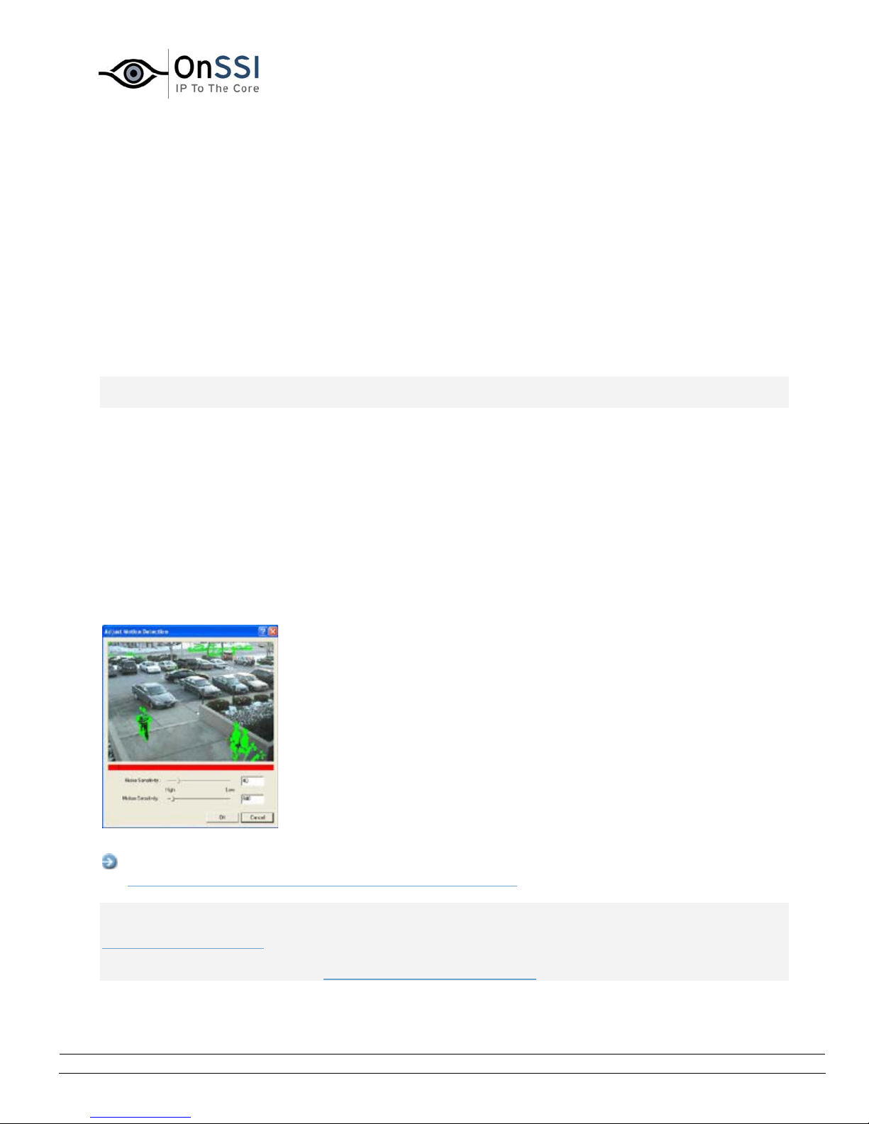
OnSSI NetDVMS Rev 6.5
Administration
• Preview Image
When adjusting camera settings, you are able to view the effect of your settings by clicking the
Preview Image button, located at the bottom of the window.
Clicking the Preview Image button will provide you with an image from the camera in question, as
it would look with the settings specified in the Camera Settings section.
When you have found the best possible camera settings, click OK to apply the settings for the
camera.
Adjust Motion Detection Window
Note: Access to features in the Administrator application, including those described in the following, may
require administrator rights.
The Adjust Motion Detection window lets you specify motion detection sensitivity for a specific camera.
Depending on your configuration, motion detection sensitivity settings may determine when recordings
from the camera are transferred to the surveillance system, when alerts are generated, when external
outputs (such as lights or sirens) are triggered, etc.
Motion detection sensitivity is therefore a key element in your NetDVMS surveillance solution, and time
spent on finding the best possible motion detection settings for each camera may help you later avoid
unnecessary alerts, etc.
Depending on the physical location of the camera, it may be a very good idea to test motion detection
settings under different physical conditions (day/night, windy/calm weather, etc.).
The Adjust Motion Detection window
Access: You access the Adjust Motion Detection window by clicking the Motion Detection... button in
the Camera Settings for [Device Name] [Camera Name] window
Note: Before you configure motion detection sensitivity for a camera, it is highly recommended that you
have configured the camera's image quality settings, such as resolution, compression, etc., in the
Configure Device window, and that you have specified any areas to be excluded from motion detection
(for example if the camera covers an area where a tree is swaying in the wind or where cars regularly
pass by in the background) in the Define Exclusion Regions window. If you later change image quality
On-Net Surveillance Systems, Inc. | 222 Route 59, Suite 303, Suffern, NY 10901 | T: 845-369-6400 | F: 845-369-8711 | www.onssi.com | [email protected] | page 38
.
Page 50

OnSSI NetDVMS Rev 6.5
Administration
settings and/or exclusion area settings, you should always test motion detection sensitivity settings
afterwards.
The Adjust Motion Detection window features two sliders; one for setting Noise Sensitivity and one for
setting Motion Sensitivity:
• Noise Sensitivity
Noise is insignificant changes in individual pixels which should not be regarded as motion.
The Noise Sensitivity slider determines how much each pixel must change before it is regarded as
motion. Insignificant changes, which should not be regarded as motion, are considered
acceptable noise, hence the name of the slider.
With a high noise sensitivity, very little change in a pixel is required before it is regarded as
motion.
Areas in which motion is detected are highlighted in the preview image. Select a slider position in
which only detections you consider motion are highlighted.
As an alternative to using the slider, you may specify a value between 0 and 256 in the field next
to the slider to control the noise sensitivity setting.
Tip: If you find the concept of noise sensitivity difficult to grasp, try dragging the slider to the
left towards the High position: The more you drag the slider towards the High position, the more
of the preview image becomes highlighted. This is because with a high noise sensitivity even the
slightest change in a pixel will be regarded as motion.
• Motion Sensitivity
The Motion Sensitivity slider determines how many pixels must change in the image before it is
regarded as motion.
The selected motion sensitivity level is indicated by the black vertical line in the motion level
indication bar below the preview image. The black vertical line serves as a threshold: When
detected motion is above the selected sensitivity level, the bar changes color from green to red,
indicating a positive detection.
As an alternative to using the slider, you may specify a value between 0 and 10,000 in the field
next to the slider to control the motion sensitivity setting.
On-Net Surveillance Systems, Inc. | 222 Route 59, Suite 303, Suffern, NY 10901 | T: 845-369-6400 | F: 845-369-8711 | www.onssi.com | [email protected] | page 39
Page 51
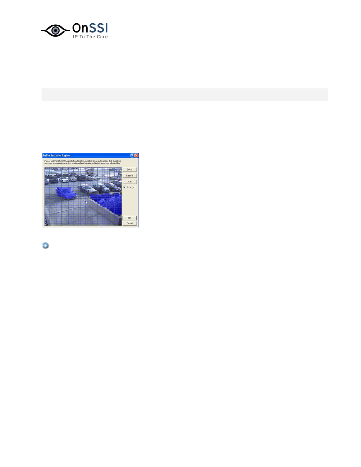
OnSSI NetDVMS Rev 6.5
Administration
Define Exclusion Regions Window
Note: Access to features in the Administrator application, including those described in the following, may
require administrator rights.
The Define Exclusion Regions window lets you disable motion detection in specific areas of a camera's
images.
Disabling motion detection in certain areas may help you avoid detection of irrelevant motion, for
example if the camera covers an area where a tree is swaying in the wind or where cars regularly pass by
in the background.
The Define Exclusion Regions window, with
an exclusion area highlighted in blue
Access: You access the Define Exclusion Regions window by clicking the Exclude Regions... button in
the Camera Settings for [Device Name] [Camera Name] window.
• Defining Areas in which Motion Detection Should Be
Disabled
The Define Exclusion Regions window features a preview image from the camera. You define the
areas in which motion detection should be disabled in the preview image, which is divided into
small sections by a grid.
To define areas in which motion detection should be disabled, drag the mouse pointer over the
required areas in the preview image while pressing the mouse button down. Left mouse button
selects a grid section; right mouse button clears a grid section. Selected areas are highlighted in
blue.
On-Net Surveillance Systems, Inc. | 222 Route 59, Suite 303, Suffern, NY 10901 | T: 845-369-6400 | F: 845-369-8711 | www.onssi.com | [email protected] | page 40
Page 52
OnSSI NetDVMS Rev 6.5
Administration
• Define Exclusion Regions Window's Buttons and Check
Boxes
The Define Exclusion Regions window features the following buttons:
Button,
Check Box
Set All Lets you quickly select all grid sections in the preview image.
Clear All Lets you quickly clear all grid sections in the preview image.
Auto By clicking the Auto button you can make NetDVMS automatically
Description
This may be advantageous if you want to disable motion detection in
most areas of the image, in which case you can simply clear the few
sections in which you do not want to disable motion detection.
detect areas with noise (insignificant changes in individual pixels
which should not be regarded as motion) in the image, and
automatically mark such areas as areas in which motion detection
should be disabled.
As the automatic detection is based on an analysis of a number of
images, it may take a few seconds from you click the Auto button to
noisy areas are detected and marked as areas in which motion
detection should be disabled.
Note: The automatic detection of noisy areas happens according to
the noise sensitivity setting specified in the Adjust Motion Detection
window. In order for the automatic detection of noisy areas to work
as intended, it is recommended that you specify a noise sensitivity
setting that matches your requirements before you make use of the
automatic detection feature.
Show Grid With the Show grid check box selected (default), the preview image
contains a grid indicating the division of the preview image into
selectable sections.
With the Show grid check box cleared, the grid in the preview image
is removed. This may provide a less obscured view of the preview
image. Selection of areas in which motion detection should be
disabled takes place the same way as when the grid is visible.
On-Net Surveillance Systems, Inc. | 222 Route 59, Suite 303, Suffern, NY 10901 | T: 845-369-6400 | F: 845-369-8711 | www.onssi.com | [email protected] | page 41
Page 53
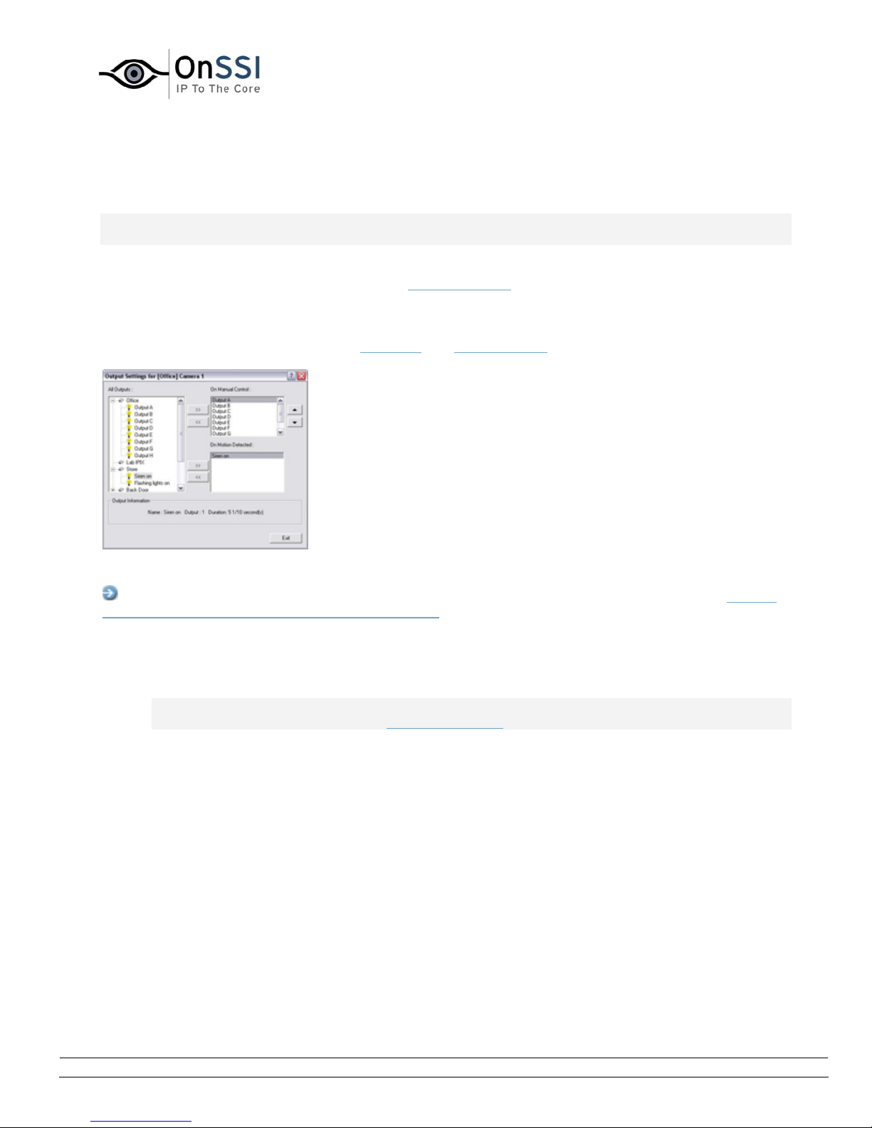
OnSSI NetDVMS Rev 6.5
Administration
Output Settings for [Device Name] [Camera Name] Window
Note: Access to features in the Administrator application, including those described in the following, may
require administrator rights.
In the Output Settings for [Device Name] [Camera Name] window you are able to associate a camera
with particular external outputs, defined in the
the switching on of lights.
The associated outputs can be triggered automatically when motion is detected as well as manually
through output buttons available in the NetGuard
I/O Setup window, for example the sounding of a siren or
and NetGuard-EVS.
The Output Settings for [Device Name]
[Camera Name] window
Access: You access the Output Settings for [Device Name] [Camera Name] window from the Camera
Settings for [Device Name] [Camera Name] window, by clicking the Outputs... button.
• Associating Outputs with Manual Control and Detected
Motion
Note: Use of features in the Output Settings for [Device Name] [Camera Name] window requires
that output has been defined in the I/O Setup window.
You have a high degree of flexibility when associating a camera with particular outputs:
• You are able to select between all available outputs, i.e. outputs defined as output events
for the camera itself as well as outputs defined as output events for other devices on the
NetDVMS system
• The same output may be used for manual control through an output button as well as
for automatic triggering when motion is detected
On-Net Surveillance Systems, Inc. | 222 Route 59, Suite 303, Suffern, NY 10901 | T: 845-369-6400 | F: 845-369-8711 | www.onssi.com | [email protected] | page 42
Page 54

OnSSI NetDVMS Rev 6.5
Administration
Selecting Output for Manual Control
You are able to specify outputs to be triggered manually from a list in the NetGuard or NetGuardEVS.
To specify an output for manual triggering in the NetGuard/NetGuard-EVS, do the following:
1. Select the required output in the All Outputs list in the left side of the Output Settings for
[Device Name] [Camera Name] window.
Tip: When you select an output in the All Outputs list, you can view detailed
information about the selected output under Output Information in the lower part of the
window.
2. Click the >> button located between the All Outputs list and the On Manual Control list.
This will copy the selected output to the On Manual Control list.
An unlimited number of outputs may be selected this way.
You are able to determine each output’s position in the NetGuard’s and NetGuard-EVS’s output
list by moving the selected output up or down in the On Manual Control list with the up and down
buttons located to the right of the list. The selected output is moved up one step each time you
click the up button. Likewise, each time you click the down button, the selected output is moved
down one step.
To remove an output from the On Manual Control list, simply select the required output, and click
the << button located between the All Outputs list and the On Manual Control list.
Selecting Output for Use on Motion Detection
You are able to select outputs to be triggered automatically when motion is detected in images
from the camera.
Tip: This feature does not require that a VMD (Video Motion Detection) event has been defined
for the camera in the I/O Setup window.
To select an output for use when motion is detected in images from the camera:
3. Select the required output in the All Outputs list in the left side of the Output Settings for
[Device Name] [Camera Name] window.
Tip: When you select an output in the All Outputs list, you can view detailed
information about the selected output under Output Information in the lower part of the
window.
4. Click the >> button located between the All Outputs list and the On Motion Detected list.
This will copy the selected output to the On Motion Detected list.
To remove an output from the On Motion Detected list, simply select the required output, and
click the << button located between the All Outputs list and the On Motion Detected list.
On-Net Surveillance Systems, Inc. | 222 Route 59, Suite 303, Suffern, NY 10901 | T: 845-369-6400 | F: 845-369-8711 | www.onssi.com | [email protected] | page 43
Page 55
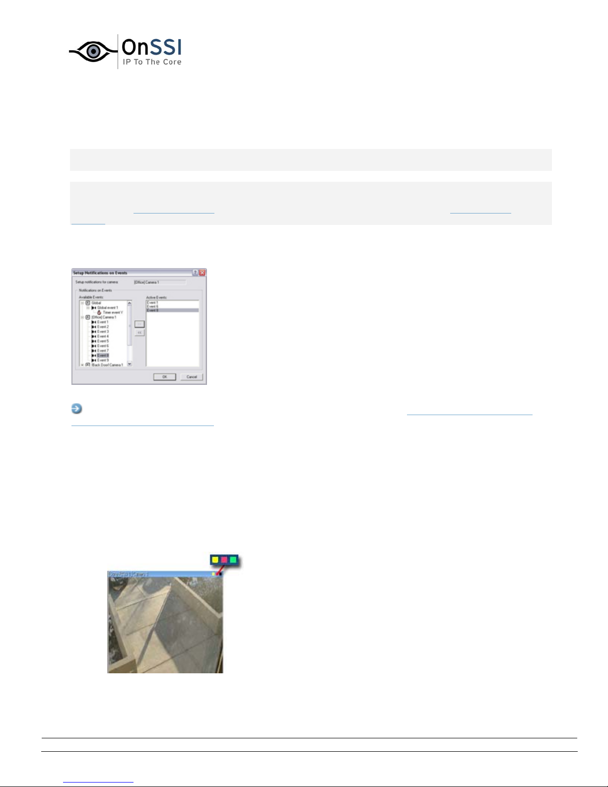
OnSSI NetDVMS Rev 6.5
Administration
Setup Notifications on Events Window
Note: Access to features in the Administrator application, including those described in the following, may
require administrator rights.
Note: The use of event notifications requires that at least one event has been specified for a device on
your NetDVMS system; the event does not have to be specified for the particular camera. You specify
events in the I/O Setup window, accessed by clicking the I/O Setup... button in the Administrator
window.
The Setup Notifications on Events window lets you select events for triggering event indications for the
camera when displayed in NetGuard and NetGuard-EVS.
The Setup Notifications on Events window
Access: You access the Setup Notifications on Events window from the Camera settings for [Device
Name] [Camera Name] window, by clicking the Event Notifications button.
• What Is an Event Indication?
In the NetGuard/NetGuard-EVS, three different color indicators are available for each camera: a
yellow indicator, a red indicator, and a green indicator. When event indication is used for a
camera, the yellow indicator will light up when the specified events have occurred.
Event indications can be valuable for camera operators, as they will be able to quickly detect that
an event has occurred, even though their focus was perhaps on something else the moment the
event occurred.
Available indicators; the yellow
indicator serves as the event
indicator
On-Net Surveillance Systems, Inc. | 222 Route 59, Suite 303, Suffern, NY 10901 | T: 845-369-6400 | F: 845-369-8711 | www.onssi.com | [email protected] | page 44
Page 56

OnSSI NetDVMS Rev 6.5
Administration
Tip: The other two indicators serve the following purposes: The red indicator lights up when
motion has been detected, and the green indicator is used for indicating that images are received
from a camera.
• Specifying Events for which Event Indication Should Be
Used
To specify which events should trigger an event indication for the camera, do the following for
each required event:
1. In the Available Events list, select the required event.
2. Click the >> button to copy the selected event to the Active Events list.
3. Repeat for each required event.
To remove an event from the Active Events list, select the event in question, and click the <<
button.
PTZ Pre
Tip: You are not limited to events associated with a particular device: You are able to
select between all available events (input events, timer events, event buttons) from all
cameras on the NetDVMS surveillance system.
When an event listed in the Active Events list occurs, the event indicator will light up.
On-Net Surveillance Systems, Inc. | 222 Route 59, Suite 303, Suffern, NY 10901 | T: 845-369-6400 | F: 845-369-8711 | www.onssi.com | [email protected] | page 45
Page 57
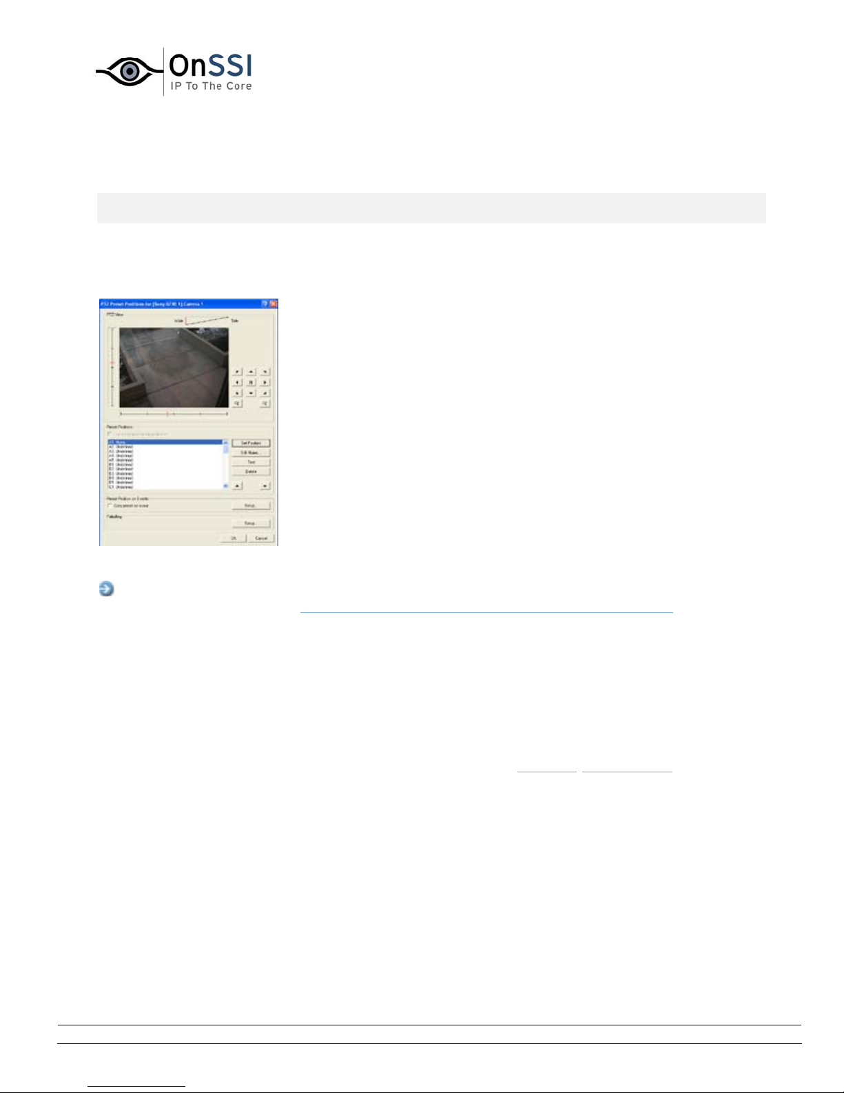
OnSSI NetDVMS Rev 6.5
Administration
set Positions for [Device Name] [Camera Name] Window
Note: Access to features in the Administrator application, including those described in the following, may
require administrator rights.
Available only when dealing with a PTZ (Pan/Tilt/Zoom) camera supporting PTZ preset positions, the PTZ
Preset Positions for [Device Name] [Camera Name] window lets you view and—for many, but not all, PTZ
cameras—define preset positions for the PTZ camera.
The PTZ Preset Positions for [Device
Name] [Camera Name] window
Access: To access the PTZ Preset Positions for [Device Name] [Camera Name] window, click the PTZ
Preset Positions... button in the Camera Settings for [Device Name [Camera Name] window. The button
is only available if the camera supports PTZ preset positions. Note that if the Recording Server service is
running, the button will not be available; see the description of the Camera Settings for [Device Name
[Camera Name] window for information about how to make the button available.
• Why Use Preset Positions?
Defined preset positions can be used for making the PTZ camera automatically go to particular
preset positions when particular events occur, and for specifying PTZ patrolling schemes.
Defined preset positions will also become selectable in the NetGuard
/NetGuard-EVS, allowing
users of these applications to move the PTZ camera to the preset positions.
• Absolute and Relative Positioning PTZ Cameras
Your configuration options depend on whether the PTZ camera in question is of the absolute
positioning or relative positioning kind:
• Absolute: For an absolute positioning PTZ camera, you are able to define up to 50 preset
positions.
You define a preset position by moving the PTZ camera to the required position with the
controls in the PTZ View section, then naming the position in the window's Preset
On-Net Surveillance Systems, Inc. | 222 Route 59, Suite 303, Suffern, NY 10901 | T: 845-369-6400 | F: 845-369-8711 | www.onssi.com | [email protected] | page 46
Page 58

OnSSI NetDVMS Rev 6.5
Administration
Positions section.
• Relative: For a relative positioning PTZ camera, the number of preset positions will
depend on the camera/video encoder and PTZ driver used.
For some relative positioning PTZ cameras you will only be able to use preset positions
defined on the camera/video encoder itself (when this is the case, the preset positions are
typically defined through the camera/video server's “built-in” web page).
For relative positioning PTZ cameras allowing definition of preset positions through the
NetDVMS system, you define a preset position by moving the PTZ camera to the required
position with the controls in the PTZ View section, then naming the position in the
window's Preset Positions section.
• How to Define a Preset Position
To define a preset position, do the following:
Note: Some PTZ cameras of the relative positioning kind do not allow you to define preset
positions as described in the following; for such cameras, you should define preset positions on
the camera/video encoder itself.
1. First use the controls in the PTZ Preset Positions for [Device Name] [Camera Name]
window's PTZ View section to move the PTZ camera to the required position.
2. Having moved the PTZ camera to the required position, select an undefined item (may be
labeled Undefined or with a position number) in the Preset Positions section's list of
preset position names, and click the Set Position button to define a name for the preset
position.
For detailed information about the functionality of PTZ Preset Positions for [Device Name]
[Camera Name] window—such as the ability to test your preset positions, the ability to
combine preset positions with events, or the ability to use preset positions in PTZ
patrolling schemes—see Preset Positions for [Device Name] [Camera Name] window's
sections in the following.
You are able to define up to 50 preset positions.
• PTZ Preset Positions for [Device Name] [Camera
Name] Window's Sections
Each of the PTZ Preset Positions for [Device Name] [Camera Name] window's sections are
described in the following:
• PTZ View Section
The PTZ View section lets you control the PTZ camera, and watch the PTZ
camera's movements. You use this section to move the PTZ camera to the
positions you then define as presets positions in the Preset Positions section.
To move the PTZ camera, simply click the required position in the preview picture.
On-Net Surveillance Systems, Inc. | 222 Route 59, Suite 303, Suffern, NY 10901 | T: 845-369-6400 | F: 845-369-8711 | www.onssi.com | [email protected] | page 47
Page 59
OnSSI NetDVMS Rev 6.5
Administration
The PTZ View section also features sliders allowing you to move the PTZ camera
along each of its axes: the X-axis (allowing you to pan left/right), the Y-axis
(allowing you to tilt the camera up/down), and the Z-axis (enabling you to zoom
in and out; the camera will zoom in when you move the slider towards Tele, and
zoom out when you move the slider towards Wide).
As an alternative to clicking the required position in th e preview or using the sliders, you
can use the PTZ camera navigation buttons:
Moves the PTZ camera up and to the left
Moves the PTZ camera up
Moves the PTZ camera up and to the right
Moves the PTZ camera to the left
Moves the PTZ camera to its home position
Moves the PTZ camera to the right
Moves the PTZ camera down and to the left
Moves the PTZ camera down
Moves the PTZ camera down and to the right
Zoom out (one zoom level per click)
Zoom in (one zoom level per click)
On-Net Surveillance Systems, Inc. | 222 Route 59, Suite 303, Suffern, NY 10901 | T: 845-369-6400 | F: 845-369-8711 | www.onssi.com | [email protected] | page 48
Page 60
OnSSI NetDVMS Rev 6.5
• Preset Positions Section
Having specified a camera position in the PTZ View section, you define the
required position as a preset in the Preset Positions section:
Button,
Check
Box
Description
Administration
Use
preset
positions
from
device
Set
Position
Available only for cameras supporting this feature.
Check box to use preset positions defined on the
camera or video encoder device.
Using preset positions from the camera or video
encoder device will clear any preset positions you have
defined for the PTZ camera; you will therefore be asked
to confirm your selection.
Note: In order for preset positions from the camera or
video encoder device to work with NetDVMS, the names
of the preset positions must contain only the characters
A-Z, a-z and 0-9, and must not contain spaces. If
preset position names on the camera or video encoder
device contain other characters, or spaces, change the
preset position names on the device before selecting
the Use preset positions from device feature.
Associates the preset position selected in the list with
the position specified in the PTZ View section.
If the preset position selected in the list is yet
undefined, you will be asked to specify a name for the
preset position.
Edit
Name...
Test Lets you test a defined preset position.
Delete Lets you delete a preset position selected in the list.
On-Net Surveillance Systems, Inc. | 222 Route 59, Suite 303, Suffern, NY 10901 | T: 845-369-6400 | F: 845-369-8711 | www.onssi.com | [email protected] | page 49
Lets you edit a preset position name selected in the list.
Only works for an already defined preset position name.
Select the required preset position in the list, then click
the Test button. The effect is displayed instantly in the
PTZ View section.
When a preset position name is deleted, it will appear
as undefined in the list.
Page 61

OnSSI NetDVMS Rev 6.5
Administration
[Move
up]
[Move
down]
Lets you move a preset position selected in the list up
and down respectively.
The selected preset position is moved one step per
click.
By moving preset position up or down, you are able to
control the sequence in which available preset positions
are presented in the NetGuard andNetGuard-EVS:
In the NetGuard andNetGuard-EVS, users select preset
positions from a list. By moving a preset position up or
down in the Preset Positions section's list, you can thus
determine the sequence in which preset positions are
presented in the NetGuard's or NetGuard-EVS's list.
Display of preset positions in . Administrators are able to specify the
sequence in which available preset positions are displayed.
• Preset Position on Events Section
If you have specified input or VMD events
,event buttons or generic events, you
are able to make the PTZ camera automatically go to particular preset positions
when particular events occur.
To configure the use of preset positions on events, click the Setup... button. This
will open the Event window (for preset positions on event), in which you are able to
associate particular preset positions with particular events.
To use preset positions on event, select the Goto preset on event check box.
• Patrolling Section
To configure PTZ patrolling (the automatic movement of a PTZ camera between
several preset positions), click the Setup... button to go to the
.
window
PTZ patrolling requires that at least two preset positions have been defined.
Setup PTZ Patrolling
On-Net Surveillance Systems, Inc. | 222 Route 59, Suite 303, Suffern, NY 10901 | T: 845-369-6400 | F: 845-369-8711 | www.onssi.com | [email protected] | page 50
Page 62
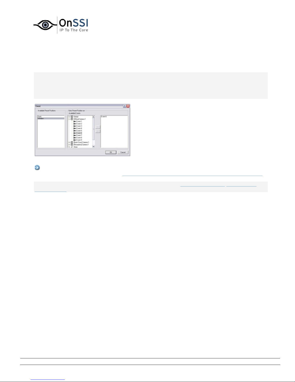
OnSSI NetDVMS Rev 6.5
Administration
Event Window (for PTZ Preset Positions on Event)
Note: Access to features in the Administrator application, including those described in the following, may
require administrator rights. Available only when dealing with a PTZ (Pan/Tilt/Zoom) camera, the Event
window (for preset positions on events) lets you associate particular preset positions with particular
events, timer events or event buttons. You are thus able to make the PTZ camera automatically go to a
particular preset position when a particular event occurs.
The Event window (for preset positions on events)
Access: To access the Event window (for preset positions on events), click the Setup... button in
Preset Position on Events section of the PTZ Preset Positions for [Device Name] [Camera Name] window
Note: To use preset positions on events, you must have specified input or VMD events,event buttons or
generic events. Only one PTZ preset position can be defined per event per camera.
• Associating Preset Positions with Particular Events
When associating a preset position from a particular PTZ camera with one or more events, you
are able to select between all events defined on the NetDVMS system; you are not limited to
selecting events defined on a particular device. To associate a particular preset position with a
particular event, do the following:
1. Select the required preset position in the Available Preset Positions list in the left side of
the Event window.
2. Select the required event in the list of available events (the list in the middle of the
window).
3. Click the >> button located to the right of the Available Events list.
This will copy the selected event to the window's rightmost list, in which events
associated with the selected preset position are listed. When the selected event occurs, or
when the selected event button is clicked, the PTZ camera will automatically move to the
required preset position.
You are able to associate a preset position with more than one event: Simply repeat the process
for each required association.
To end the association between a particular preset position and a particular event, simply select
the required event in the window's rightmost list, and click the << button.
.
On-Net Surveillance Systems, Inc. | 222 Route 59, Suite 303, Suffern, NY 10901 | T: 845-369-6400 | F: 845-369-8711 | www.onssi.com | [email protected] | page 51
Page 63
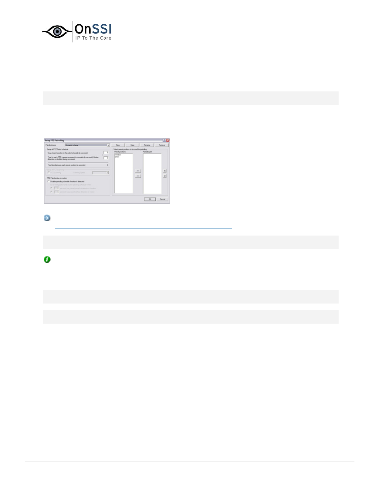
OnSSI NetDVMS Rev 6.5
Administration
Setup PTZ Patrolling Window
Note: Access to features in the Administrator application, including those described in the following, may
require administrator rights.
Available only when dealing with a PTZ (Pan/Tilt/Zoom) camera, the Setup PTZ Patrolling window lets you
configure patrol schemes for PTZ patrolling (the automatic movement of a PTZ camera between several
preset positions) for the camera.
The Setup PTZ Patrolling window
Access: To access the Setup PTZ Patrolling window, click the Setup... button in Patrolling section of
the PTZ Preset Positions for [Device Name] [Camera Name] window.
Note: To use patrolling, you must have specified at least two preset positions for the PTZ camera in
question.
Tip: Although it is technically not patrolling, specifying a patrol scheme with only one preset position is
possible. A patrol scheme with only one preset position can, when combined with scheduling, be useful in
two cases: For moving a PTZ camera to a specific position at a specific time, and for moving a PTZ
camera to a specific position upon manual PTZ control of the camera.
Note: When you have defined your patrol schemes, also remember to schedule use of the patrol
schemes in the Camera/Alert Scheduler window.
Note: Bear in mind that patrolling can be overridden if operators (with the necessary user rights)
manually control PTZ cameras.
• Patrol Scheme
A PTZ camera may patrol according to several different patrol schemes. For example, a PTZ
camera in a supermarket may patrol according to one patrol scheme during opening hours, and
according to another patrol scheme when the supermarket is closed.
The Patrol scheme list lets you select which patrol scheme to configure.
Defining a New Patrol Scheme
To define a new patrol scheme, click the New button. This will add a New patrol scheme listing to
the Patrol scheme list.
On-Net Surveillance Systems, Inc. | 222 Route 59, Suite 303, Suffern, NY 10901 | T: 845-369-6400 | F: 845-369-8711 | www.onssi.com | [email protected] | page 52
Page 64

OnSSI NetDVMS Rev 6.5
Administration
To change the name from New patrol scheme to a name of your choice, select the New patrol
scheme listing, and click the Rename button.
Copying an Existing Patrol Scheme
If you want to create a new patrol scheme based on an existing one, you can copy the existing
patrol scheme.
To copy an existing patrol scheme, select the required patrol scheme in the Patrol scheme list,
and click the Copy button. This will add a copy of the selected patrol scheme to the list.
The copy will initially be named Copy of [Patrol Scheme Name]. To change the name to a name of
your choice, select the Copy of [Patrol Scheme Name] listing, and click the Rename button.
Renaming an Existing Patrol Scheme
To change the name of an existing patrol scheme, select the required patrol scheme in the Patrol
scheme list, and click the Rename button.
Removing an Existing Patrol Scheme
To remove an existing patrol scheme, select the required patrol scheme in the Patrol scheme list,
and click the Remove button.
Note: The selected patrol scheme will be removed from the list without further warning.
• Selecting Preset Positions to Be Used for a PTZ Patrol
Scheme
Having selected a patrolling scheme in the Patrol scheme list, you are able to specify which of the
PTZ camera's preset positions should be used for the selected patrolling scheme:
1. In the Preset Positions list, select the names of the preset positions you want to use.
2. Click the >> button to copy the selected preset positions to the Patrolling list.
3. The camera will move between preset positions in the sequence they appear in the
To remove a preset position from the Patrolling list, select the preset position in question, and
click the << button.
A preset position can be used more than once in a patrol scheme, for example if the
preset position covers an especially important location.
Tip: By pressing the CTRL or SHIFT buttons on your keyboard while selecting from the
Preset Positions list, you are able to select several or all of list's preset positions in one
go.
Patrolling list, starting at the preset position listed first.
If you want to change the sequence of preset positions in the Preset Positions list, select
a preset position name, and use the move up or move down buttons to move the selected
preset position name.
On-Net Surveillance Systems, Inc. | 222 Route 59, Suite 303, Suffern, NY 10901 | T: 845-369-6400 | F: 845-369-8711 | www.onssi.com | [email protected] | page 53
Page 65

OnSSI NetDVMS Rev 6.5
Administration
• Specifying Timing Settings for a PTZ Patrol Scheme
Having selected a patrolling scheme in the Patrol scheme list, you are able to specify timing
settings for the patrol scheme:
1. In the Stay at each position in the patrol schedule field, specify the number of seconds for
which the PTZ camera should stay at each preset position.
2. In the Time for each PTZ camera movement to complete field, specify the number of
seconds required for the PTZ camera to move between preset positions.
In order not to generate false motion alarms, motion detection for the PTZ camera is
automatically disabled while the camera moves between two preset positions. After the
specified number of seconds, motion detection is automatically enabled again.
It is thus important that the camera is able to reach all of the patrolling scheme's preset
positions within the number of seconds you specify. If not, false motion is likely to be
detected.
Bear in mind that it takes longer for the PTZ camera to move between positions that are
located physically far apart (e.g. from an extreme left position to an extreme right
position) than between positions that are located physically close together.
3. The total number of seconds between each preset position will be listed below the two
fields.
• PTZ Patrolling Actions on Detected Motion
You are able to combine a PTZ patrol scheme with motion detection, so that when motion is
detected, the PTZ camera will pause its patrolling and remain at the position where motion was
detected for a specified period of time.
To use this feature, do the following:
1. Select the Disable patrolling schedule if motion is detected check box.
2. Select whether the PTZ camera should resume patrolling:
• When a certain number of seconds has passed since first detection of motion,
regardless whether further motion is detected, or,
• When a certain number of seconds has passed without further detection of motion
3. Specify the required number of seconds for selected option.
Example: You may specify that the PTZ camera should go to the next preset position and
resume patrolling when 10 seconds has passed without detection of motion.
• PTZ Scanning
PTZ scanning is supported on a few devices only. If your device supports PTZ scanning, the Setup
of PTZ Scanning section lets you enable PTZ scanning and select a PTZ scanning speed.
On-Net Surveillance Systems, Inc. | 222 Route 59, Suite 303, Suffern, NY 10901 | T: 845-369-6400 | F: 845-369-8711 | www.onssi.com | [email protected] | page 54
Page 66
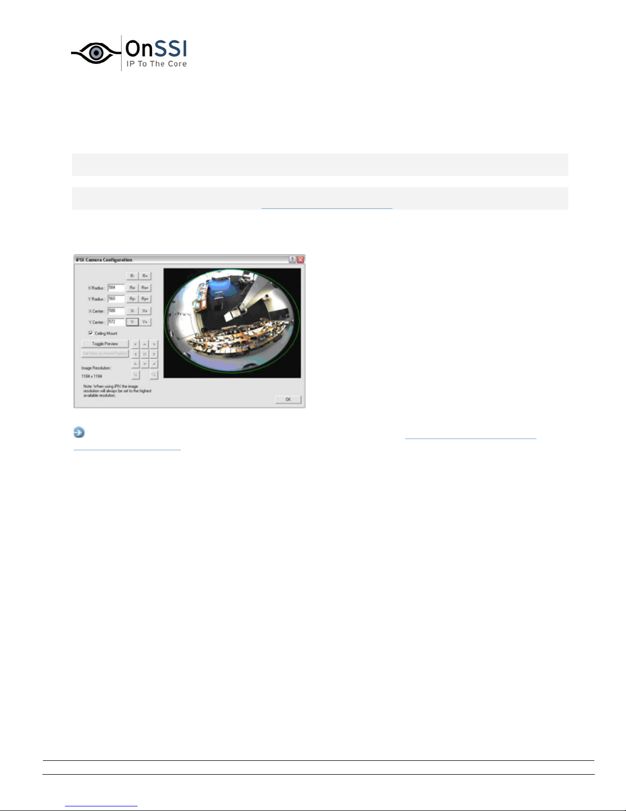
OnSSI NetDVMS Rev 6.5
Administration
iPIX Camera Configuration Window
Note: Access to features in the Administrator application, including those described in the following, may
require administrator rights.
Note: Use of the IPIX technology requires a dedicated IPIX camera or a special IPIX camera lens with a
special IPIX license key, specified in the Edit Device Settings window.
IPIX is a technology that allows viewing of 360-degree panoramic images through an advanced ”fish eye”
lens. The iPIX Camera Configuration window lets you configure the IPIX functionality of a camera.
The iPIX Camera Configuration window
Access: You access the iPIX Camera Configuration window from the Camera Settings for [Device
Name] [Camera name] window, by selecting the Enable iPIX check box, and clicking the iPIX Settings...
button.
On-Net Surveillance Systems, Inc. | 222 Route 59, Suite 303, Suffern, NY 10901 | T: 845-369-6400 | F: 845-369-8711 | www.onssi.com | [email protected] | page 55
Page 67
OnSSI NetDVMS Rev 6.5
Administration
• IPIX View Adjustment
The camera's IPIX functionality is configured by adjusting its IPIX view field, indicated by a green ellipse in
the preview image, so it encloses the actual image ar ea of the “fish eye” lens.
You do this by specifying a number of values which will be used by the IPIX technology f o r converting the
elliptic image into an ordinary rectangular image.
You are able to set the ellipse's X-radius, Y-radius, X-center, and Y-center, either by specifying the required
values directly in the four fields, or by using the following buttons to adjust the ellipse:
Button Description
R- Decreases the radius of the IPIX view field.
The ellipse's horizontal (X) and vertical (Y) radiuses are changed at
the same time, keeping the aspect ratio.
R+ Increases the radius of the IPIX view field.
The ellipse's horizontal (X) and vertical (Y) radiuses are changed at
the same time, keeping the aspect ratio.
Rx- Decreases the horizontal (X) radius of the ellipse.
Rx+ Increases the horizontal (X) radius of the ellipse.
Ry- Decreases the vertical (Y) radius of the ellipse.
Ry+ Increases the vertical (Y) radius of the ellipse.
X- Moves the ellipse to the left.
X+ Moves the ellipse to the right.
Y- Moves the ellipse up.
Y+ Moves the ellipse down.
On-Net Surveillance Systems, Inc. | 222 Route 59, Suite 303, Suffern, NY 10901 | T: 845-369-6400 | F: 845-369-8711 | www.onssi.com | [email protected] | page 56
Page 68
OnSSI NetDVMS Rev 6.5
Administration
• Previewing the IPIX View
You are able to toggle between previewing the ”fish eye” view and the IPIX-rendered view, i.e.
the original elliptic view as well as the ”r;flattened” rectangular view resulting from applying the
IPIX algorithm according to your specified values. To toggle between the two different types of
preview, click the Toggle Preview button. When previewing the IPIX-rendered view, the following
navigation buttons become available for moving around within the preview image area:
Moves the IPIX-rendered view up and to the left
Moves the IPIX-rendered view up
Moves the IPIX-rendered view up and to the right
Moves the IPIX-rendered view to the left
Moves the IPIX-rendered view to its home position
Moves the IPIX-rendered view to the right
Moves the IPIX-rendered view down and to the left
Moves the IPIX-rendered view down
Moves the IPIX-rendered view down and to the right
Zoom out (one zoom level per click)
Zoom in (one zoom level per click)
Ceiling Mounted Cameras
If the camera is mounted on a ceiling, you can adjust the behavior of the navigation buttons to
reflect this by selecting the Ceiling Mount check box.
Setting a View as Home Position
When previewing the IPIX-rendered view, you are able to set a particular position in the IPIXrendered view as the camera's PTZ home position: Navigate to the required position, using the
navigation buttons, then click the Set View as Home Position button.
• Image Resolution
Image resolution values are automatically displayed in the lower part of the window, next to the
navigation buttons. When using IPIX, image resolution will automatically be set to the highest
available resolution.
On-Net Surveillance Systems, Inc. | 222 Route 59, Suite 303, Suffern, NY 10901 | T: 845-369-6400 | F: 845-369-8711 | www.onssi.com | [email protected] | page 57
Page 69
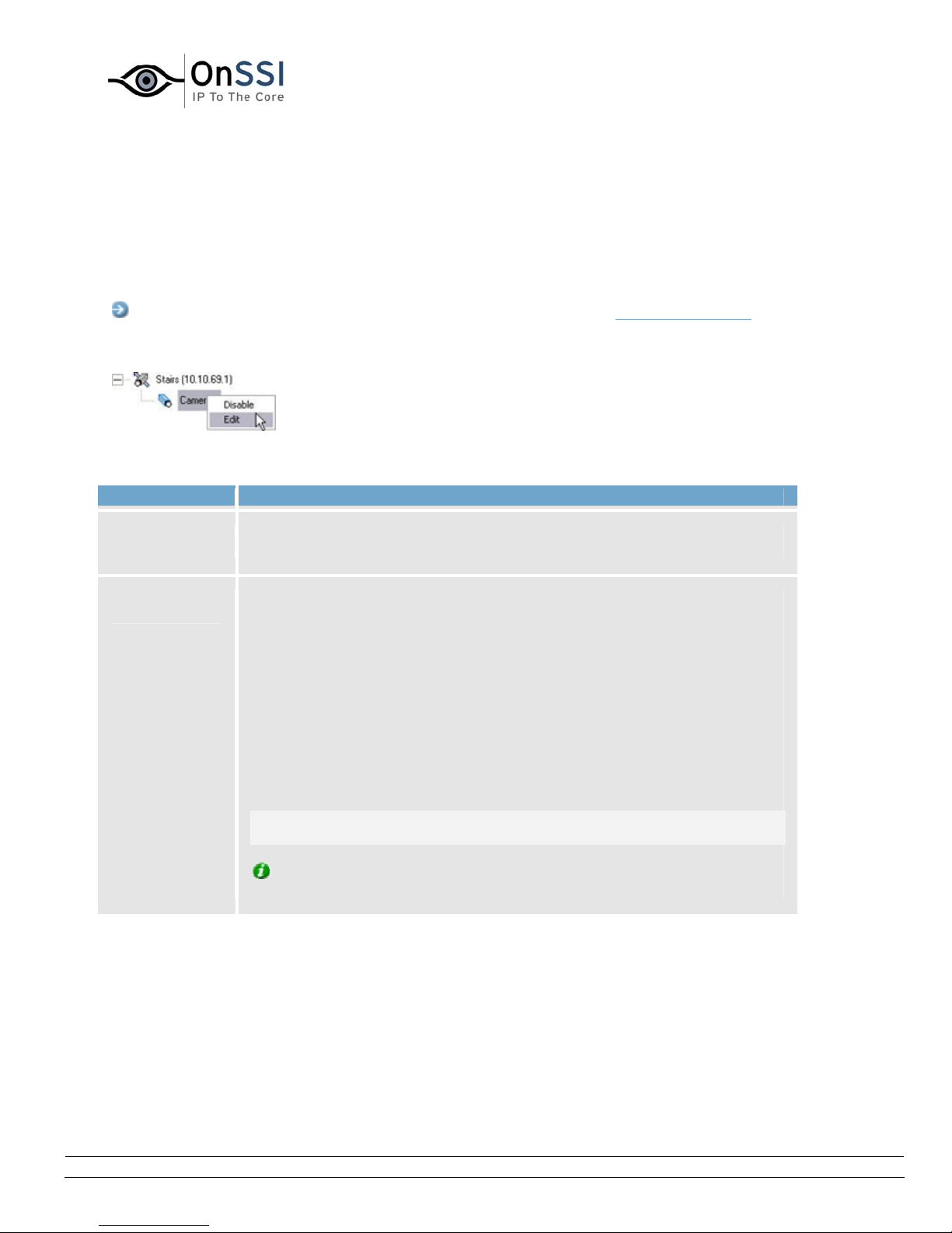
OnSSI NetDVMS Rev 6.5
Administration
Camera Name and Number Window
The Camera Name and Number window lets you edit the name of a selected camera, and, if required,
assign a shortcut number to the selected camera.
Access: You access the Camera Name and Number window from the Administrator window's device
Manager section: Right-click the name of the required camera, then select Edit from the menu that
appears:
The Camera Name and Number window contains two fields:
Field Description
Camera
Name
Camera
Number
Displays the name of the camera. If required, you are able to overwrite
the existing camera name with a new one.
Users of the scname can take advantage of a range of keyboard shortcuts,
some of which let the users toggle between viewing different cameras.
Such shortcuts include numbers, which are used to identify each camera.
Each camera's shortcut number is specified in the Cam Number field.
A camera shortcut number must not contain any letters or special
characters, and must be no longer than eight digits. Examples of correct
camera shortcut numbers: 3, 12345678. Examples of incorrect camera
shortcut numbers: A*3, 123456789.
It is highly recommended that you use a unique camera shortcut number
for each camera.
Note: Camera shortcut numbers are only used in the scname. In other
applications, such as the NetGuard, the camera shortcuts cannot be used.
Tip: More information about using keyboard shortcuts in the scname is
available in Using Standard Keyboard Shortcuts.
On-Net Surveillance Systems, Inc. | 222 Route 59, Suite 303, Suffern, NY 10901 | T: 845-369-6400 | F: 845-369-8711 | www.onssi.com | [email protected] | page 58
Page 70

OnSSI NetDVMS Rev 6.5
Administration
Audio Source Administration
Important Information about Using Audio
If you use audio sources (i.e. microphones and/or speakers) on your NetDVMS system, note the
following:
• Only audio from microphones is recorded: Onl y in coming audio, i.e. audio recorded by
microphones attached to cameras, is recorded. Outgoing audio, i.e. what NetGuard-EVS operators
say when they talk through speakers attached to cameras, is not recorded.
• Audio from microphones is recorded even when video is not: When a microphone is enabled (see
Microphone Settings Window), audio from the microphone will be recorded whenever the associated
camera is online (i.e. transmitting data to NetDVMS; see
regardless whether video from the camera is being recorded or not.
Depending on your cameras’ recording settings, this may mean that when you play back
recordings, you may find that there are periods for which you only have audio recordings. This
will also be the case for exported recordings if audio has been included in the export.
Camera/Alert Scheduler Window),
• Audio recording affects video storage capacity: When a microphone is enabled, audio is
recorded to the associated camera’s database. This will affect the database’s capacity for storing
video. A camera’s database can contain a maximum of 40 GB or 600,000 records. It is thus
important to bear in mind that the maximum limit of the database is likely to be reached earlier if
recording audio and video than if only recording video.
o Example: If using MPEG4, each one-second video GOP (Group Of Pictures) will be stored
in one record in the database. Each second of audio will also be stored in one record in
the database. When this is the case, the database’s video storage capacity will be reduced
to a maximum of 300,000 records, because half of the database’s total maximum of
600,000 records will be used for storing audio.
o Example: If using MJPEG, audio is stored in one record for every JPEG for as long as the
audio block size does not exceed the time between the JPEGs. The database’s video
storage capacity can thus in extreme cases be reduced to a maximum of 300,000
records, because half of the database’s total maximum of 600,000 records will be used
for storing audio. If using very high frame rates, where there is less time between each
JPEG, a smaller portion of the database will be used for storing audio records, and
consequently a larger portion will be available for storing video.
Thus, a camera database’s maximum video storage capacity may in some cases be halved when
an associated audio source is enabled.
Note: Above examples are simplified. Since databases also have a maximum limit of 40 GB of
data, the exact available video storage capacity will also depend on GOP/JPEG and audio kilobyte
size.
Tip: The Archiving feature enables you to store recordings beyond the capabilities of cameras’
databases.
On-Net Surveillance Systems, Inc. | 222 Route 59, Suite 303, Suffern, NY 10901 | T: 845-369-6400 | F: 845-369-8711 | www.onssi.com | [email protected] | page 59
Page 71

OnSSI NetDVMS Rev 6.5
Administration
Microphone Settings Window
Note: Access to features in the Administrator application, including those described in the following, may
require administrator rights.
The Microphone Settings window lets you change basic settings for a microphone.
Access: You access the Microphone Settings window from the Administrator window: Selecting a
microphone in the Administrator window's Device Manager section, then click the Settings button.
• Device name: Displays the name of the microphone. If required, you are able to overwrite the
existing microphone name with a new one.
• Enabled: Lets you enable/disable use of the microphone.
Tip: You can also enable/disable a microphone in the Administrator window: right-click the
required microphone in the Administrator window's Device Manager section, the select Disable or
Enable from the menu that appears.
Note: On some devices, a microphone can also be enabled/disabled on the device itself,
typically through the device's own configuration web page. If a microphone on a device does not
work after enabling it in the Administrator application, you should thus verify whether the
problem may be due to the microphone being disabled on the device itself.
Speaker Settings Window
Note: Access to features in the Administrator application, including those described in the following, may
require administrator rights.
The Speaker Settings window lets you change basic settings for a speaker.
Access: You access the Speaker Settings window from the Administrator window: Selecting a speaker in
the Administrator window's Device Manager section, then click the Settings button.
• Device name: Displays the name of the speaker. If required, you are able to overwrite the
existing speaker name with a new one.
• Enabled: Lets you enable/disable use of the speaker.
Tip: You can also enable/disable a speaker in the Administrator window: right-click the
required speaker in the Administrator window's Device Manager section, the select Disable or
Enable from the menu that appears.
Note: On some devices, a speaker can also be enabled/disabled on the device itself, typically
through the device's own configuration web page. If a speaker on a device does not work after
enabling it in the Administrator application, you should thus verify whether the problem may be
due to the speaker being disabled on the device itself.
On-Net Surveillance Systems, Inc. | 222 Route 59, Suite 303, Suffern, NY 10901 | T: 845-369-6400 | F: 845-369-8711 | www.onssi.com | [email protected] | page 60
Page 72
OnSSI NetDVMS Rev 6.5
Administration
Recording Server Service Management
Using the Recording Server Manager
Note: Access to features in the Administrator application, including those described in the following, may
require administrator rights.
The Recording Server service is a vital part of the surveillance system; video streams are only transferred
to NetDVMS while the Recording Server service is running.
The Recording Server Manager informs you about the state of the Recording Server service, and lets you
easily manage the service.
In the notification area of you desktop you can see an icon that indicates whether the Recording Server
service is running or not. If it is running, the right side of the icon is green, and if it is not running, it is
red. By default it is running.
Tip: The notification area is occasionally also known as the system tray. It is usually located in the far
right of your Windows taskbar.
The Recording Server Manager icon in the notification area
of your desktop.
The Recording Server Manager icon
can be either green or red
On-Net Surveillance Systems, Inc. | 222 Route 59, Suite 303, Suffern, NY 10901 | T: 845-369-6400 | F: 845-369-8711 | www.onssi.com | [email protected] | page 61
Page 73
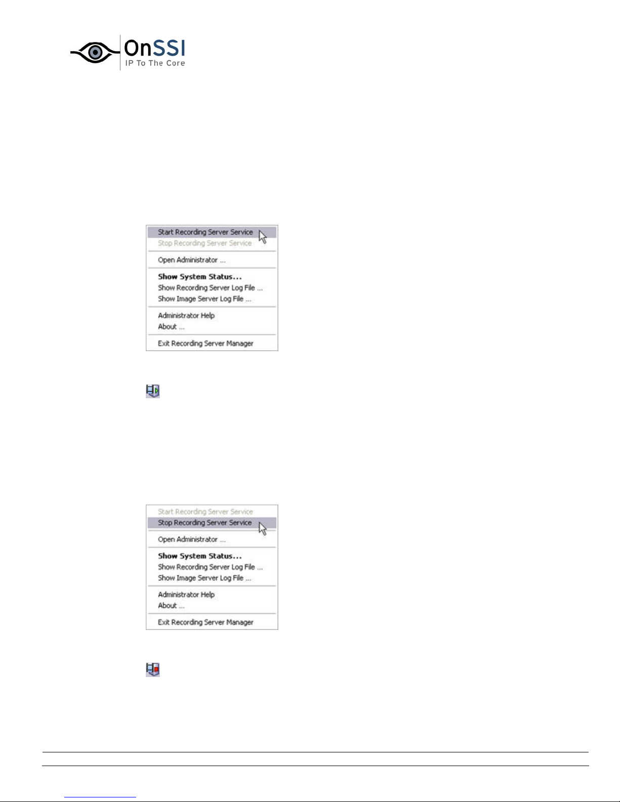
OnSSI NetDVMS Rev 6.5
Administration
By right-clicking the icon you can start and stop the Recording Server service, view log files, etc.
• Start the Recording Server
To start the Recording Server service, do the following:
1. Right-click the notification area's Recording Server icon.
2. In the menu that appears, select Start Recording Server Service.
3. The icon in the notification area changes to green.
• Stop the Recording Server
To stop the Recording Server service, do the following:
1. Right-click the notification area's Recording Server icon.
2. In the menu that appears, select Stop Recording Server Service.
3. The icon in the notification area changes to red.
On-Net Surveillance Systems, Inc. | 222 Route 59, Suite 303, Suffern, NY 10901 | T: 845-369-6400 | F: 845-369-8711 | www.onssi.com | [email protected] | page 62
Page 74

OnSSI NetDVMS Rev 6.5
Administration
• Open the NetDVMS Application
If you right-click the notification area's Recording Server icon and select Open Administrator, the
NetDVMS Application will open.
• Show the System Status
If you right-click the notification area's Recording Server icon and select Show System Status or if
you double-click on the Recording Server icon in the notification area, the Status window
appears.
It lets you view the status of the image server(s) and the cameras connected to it/them. The
status of each server/camera is indicated by a color code:
• Green indicates that the server or camera is running correctly.
• Gray indicates that the camera (not the server) is not running. Typically, a camera will be
indicated by gray in the following situations:
o the camera has been set offline in the Camera Alert Schedular window.
o the Recording Server service has been paused from the Service Manager window.
o the Recording Server service has been stopped. See Stop the Recording Server
previously.
• Red indicates that the server or camera is not running. This may because it has been
unplugged of if there is an error on the network or the hardware. In the Recording Server
log file (described in the following) the errors are listed.
By placing your mouse pointer over a camera in the status window, you will see at tool tip that
contains information about that particular camera. The tool tip updates approximately every 10
seconds.
• Resolution: Shows the resolution of the camera.
• FPS: Shows frames per second (also knows as "frame rate") currently used by the
camera. The number updates each time the camera has received 50 frames.
• Frame count: The number of frames received from the camera since the Recording
Server was last started.
• Received KB: Shows the number of kilobytes sent the by camera since the Recording
Server was last started.
• Offline: Indicates the number of times the camera has been offline due to an error.
On-Net Surveillance Systems, Inc. | 222 Route 59, Suite 303, Suffern, NY 10901 | T: 845-369-6400 | F: 845-369-8711 | www.onssi.com | [email protected] | page 63
Page 75
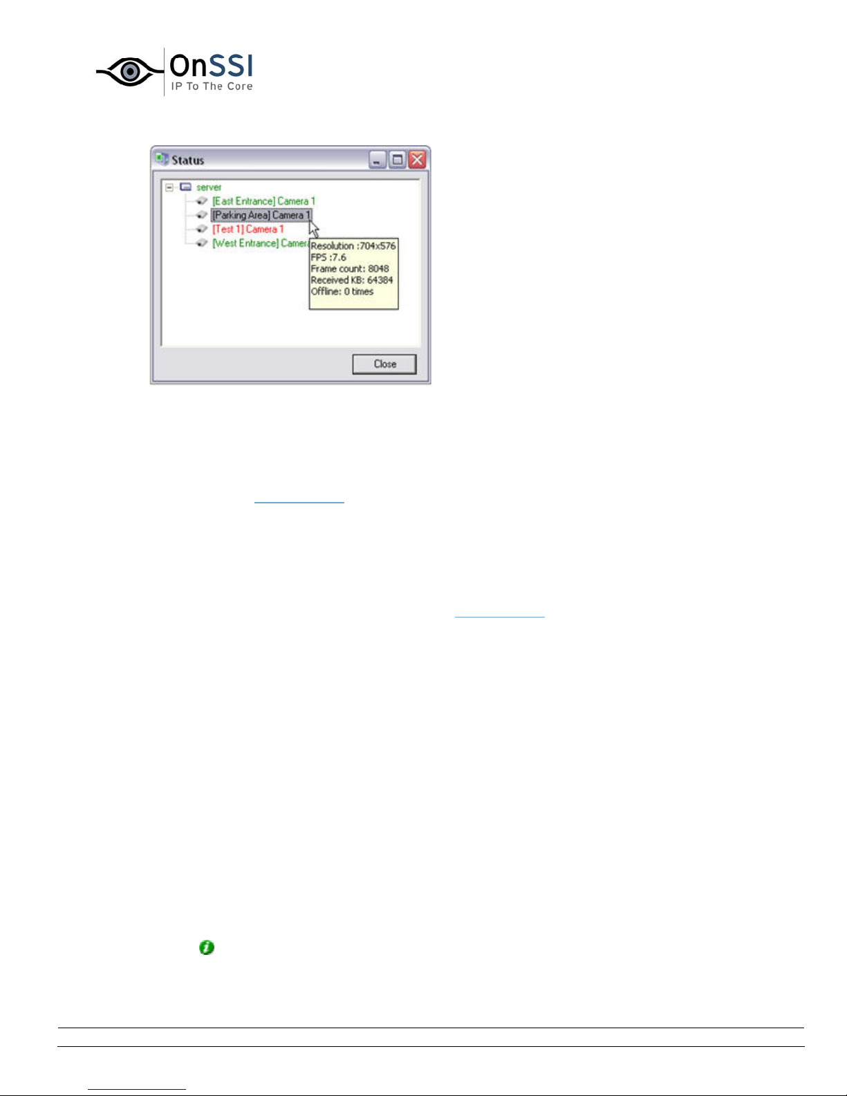
OnSSI NetDVMS Rev 6.5
Administration
The Status window with information about the server
and the connected cameras.
• Show the Recording Server Log File
If you right-click the notification area's Recording Server icon and select Open Recording
Server Log File... the Recording Server Log File will open. For more information about log
files see About Logging
.
• Show the Image Server Log File
If you right-click the notification area's Recording Server icon and select Open Image
Server Log File... the Image Server Log File will open.
For more information about log files see About Logging
• Open the Build-in Help System
If you right-click the notification area's Recording Server icon and select Administrator
Help, you open the built-in help system. See Using the Built-in Help System.
• About NetDVMS
If you right-click the notification area's Recording Server icon and select About... you will
see a small window that contains information about your NetDVMS Application. An
important piece of information in the window is the version number of your NetDVMS
Application. It can be useful to know the version number in case you require support from
your vendor.
• Exit the Recording Server Manager
You can exit the Recording Server Manager by right-clicking the notification area's
recording server icon and select Exit Recording Server Manager.
Tip: To re-open the Recording Server Manager, go to your Windows' start menu and
choose All Programs>Startup>NetDVMS Recording Server Manager.
.
On-Net Surveillance Systems, Inc. | 222 Route 59, Suite 303, Suffern, NY 10901 | T: 845-369-6400 | F: 845-369-8711 | www.onssi.com | [email protected] | page 64
Page 76
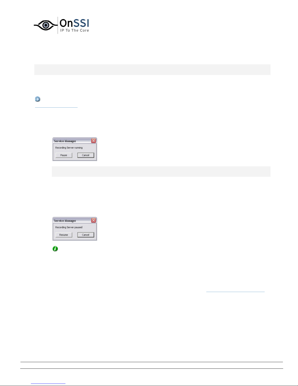
OnSSI NetDVMS Rev 6.5
Administration
Service Manager Window
Note: Access to features in the Administrator application, including those described in the following, may
require administrator rights.
The Service Manager window lets you pause/resume the Recording Server service. Pausing the service is
necessary in order to access some features, such as configuration of PTZ (Pan/Tilt/Zoom) cameras.
Access: You access the Service Manager window by clicking the Service Manager... button in the
Administrator window.
• Pausing the Recording Server Service
To pause theRecording Server service, click the Pause button.
IMPORTANT: While the Recording Server service is paused, no video or audio will be available;
neither for live viewing, nor for recording.
• Resuming the Recording Server Service
When the service is paused, the Service Manager window closes. The next time you open it, the
Pause button will have changed to Resume. Simply click the Resume button to resume
theRecording Server service:
Tip: The service is automatically resumed when you exit the Administrator application.
• What to Do if the Recording Server Service is Stopped
If the Service Manager window informs you that the recording server is stopped, the Recording
Server service has been stopped (as opposed to paused) outside the Administrator application.
You are able to start a stopped Recording Server service through the Recording Server Manager
.
On-Net Surveillance Systems, Inc. | 222 Route 59, Suite 303, Suffern, NY 10901 | T: 845-369-6400 | F: 845-369-8711 | www.onssi.com | [email protected] | page 65
Page 77
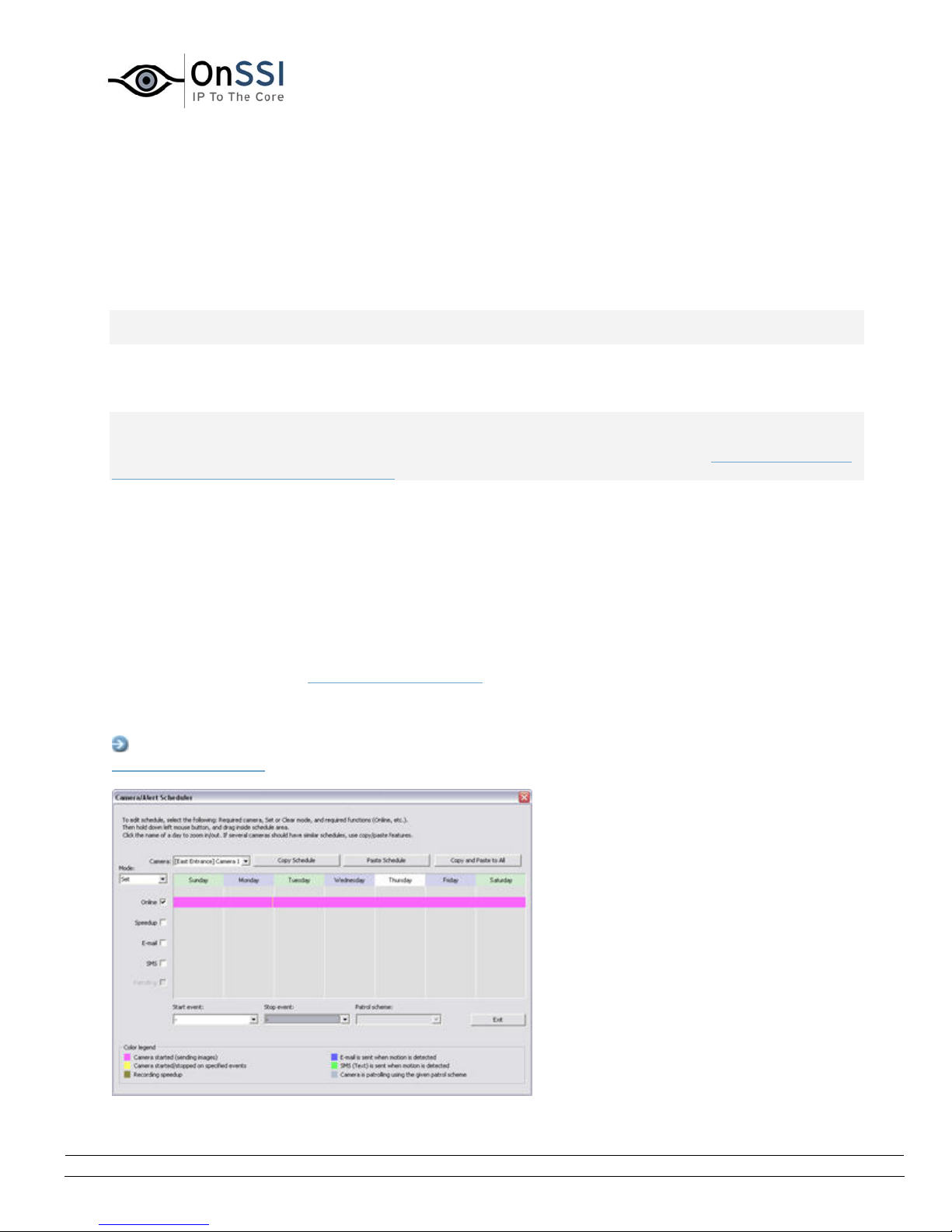
OnSSI NetDVMS Rev 6.5
Administration
Scheduling
Camera/Alert Scheduler Window
Note: Access to features in the Administrator application, including those described in the following, may
require administrator rights.
The Camera/Alert Scheduler window lets you specify when each camera should be online. A camera is
online when it is transferring images to the NetDVMS server for processing.
IMPORTANT: The fact that a camera is online (i.e. transferring images to the NetDVMS server) will not
necessarily mean that images from the camera are recorded (i.e. stored in the camera’s database on the
NetDVMS server). Image storage settings for individual cameras are specified in the Camera Settings for
[Device Name] [Camera Name] Window.
You are able to specify whether cameras should be online within specific periods of time, or whether they
should start and stop transferring images when specific events occur within specific periods of time. You
are also able to specify when the camera should speedup recording and if e-mail alerts or SMS alerts
should be triggered if motion is detected during specific periods of time. If using PTZ cameras with
patrolling, you are furthermore able to specify if certain patrol schemes should be used during specific
periods of time.
By default, cameras added to NetDVMS will automatically be online, and you will only need to modify the
Camera/Alert Scheduler window's settings if you require cameras to be online only at specific times or
events, or if you want to use specific alerts or PTZ patrol schemes. Note, however, that this default may
be changed by clearing the General Settings window
box: If the check box is cleared, subsequently added cameras will not automatically be online, in which
case online schedules must be specified manually.
Access: To access the Camera/Alert Scheduler window, click the Scheduler... button in the
Administrator window
.
's Create Default schedule for new cameras check
Camera/Alert Scheduler window
On-Net Surveillance Systems, Inc. | 222 Route 59, Suite 303, Suffern, NY 10901 | T: 845-369-6400 | F: 845-369-8711 | www.onssi.com | [email protected] | page 66
Page 78
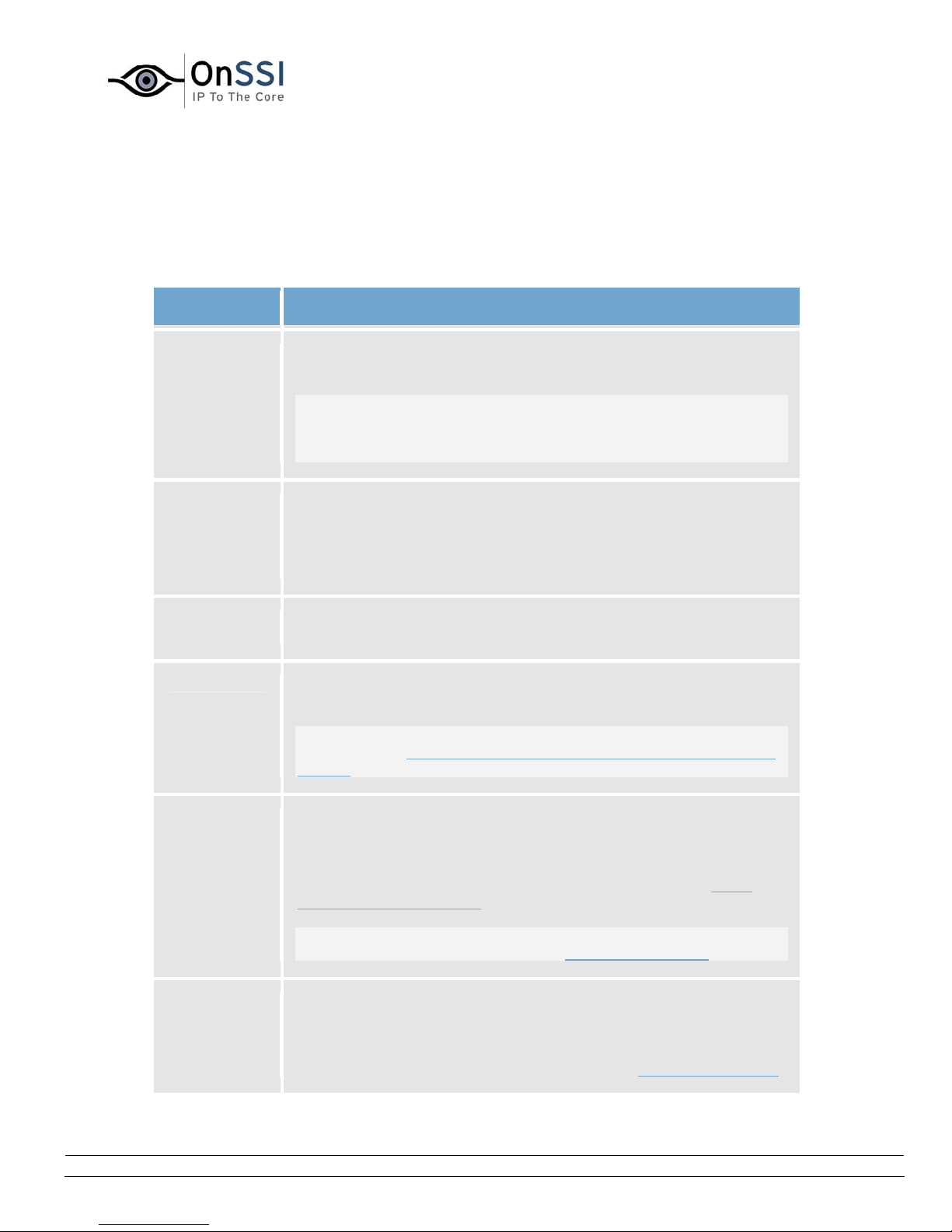
OnSSI NetDVMS Rev 6.5
• Camera/Alert Scheduler Window's Fields and Check
Administration
Boxes
The Camera/Alert Scheduler Window features the following fields and check boxes:
Field, Check
Box
Camera Lets you select a particular camera, for which to specify or view a
Mode Select whether to add or delete periods in the calendar section:
Description
schedule in the window's calendar section.
Note: Always verify that you have selected the required camera in
the list; even though schedules displayed in the calendar section
may look—and indeed sometimes be—similar, the displayed
schedule refers specifically to the selected camera.
• Set: Add periods. May also be used to overwrite existing
periods.
• Clear: Delete existing periods.
Online Check the Online box when you want to set or clear online periods
for the selected camera.
Speedup Check the Speedup box when you want to set or clear when the
camera should always/never speedup recording.
Note: The Speedup check box is only available if you have enabled
speedup in the Camera Settings for [Device Name] [Camera Name]
window.
E-mail Check the E-mail box when you want to set or clear periods with e-
mail alerts for the selected camera.
Such e-mail alerts can automatically be sent to one or more
recipients when motion is detected or specific events (see About
Input, Events & Output ...) occur.
Note: In order to be able to use e-mail alerts, the e-mail alert
feature must have been set up in the E-Mail setup window.
SMS Check the SMS box when you want to set or clear periods with SMS
(mobile phone text message) alerts for the selected camera.
Such SMS alerts can automatically be sent to one or more recipients
when motion is detected or specific events (see About Input, Events
On-Net Surveillance Systems, Inc. | 222 Route 59, Suite 303, Suffern, NY 10901 | T: 845-369-6400 | F: 845-369-8711 | www.onssi.com | [email protected] | page 67
Page 79
OnSSI NetDVMS Rev 6.5
Administration
& Output ...) occur.
Note: In order to be able to use SMS alerts, the SMS alert feature
must have been set up in the SMS settings window.
Patrolling Check the Patrolling box when you want to set or clear periods with
patrolling for a selected PTZ (Pan/Tilt/Zoom)camera.
Note: The Patrolling box is only available if you have selected a PTZ
camera for which at least one patrol scheme has been set up.
Start event When you set an Online period, you will be asked whether you want
the selected camera to transfer images to the NetDVMS software
continuously within the specified period (Always), or only when an
event occurs within the specified period (On Event).
If using On Event, the Start event list lets you select the required
start event.
Note: The use of event-based online periods requires that events
have been defined. Read more about events in About Input, Events
& Output ...
Stop event When you set an Online period, you will be asked whether you want
the selected camera to transfer images to the NetDVMS software
continuously within the specified period (Always), or only when an
event occurs within the specified period (On Event).
If using On Event, the Stop event list lets you select the required
stop event.
Note: The use of event-based online periods requires that events
have been defined. Read more about events in About Input, Events
& Output ...
Patrol
scheme
When you set a Patrolling period for a PTZ camera with patrolling,
the Patrol scheme list lets you select the required patrol scheme.
Note: The Patrol scheme list is only available if you have selected a
PTZ camera for which at least one patrol scheme has been set up.
On-Net Surveillance Systems, Inc. | 222 Route 59, Suite 303, Suffern, NY 10901 | T: 845-369-6400 | F: 845-369-8711 | www.onssi.com | [email protected] | page 68
Page 80
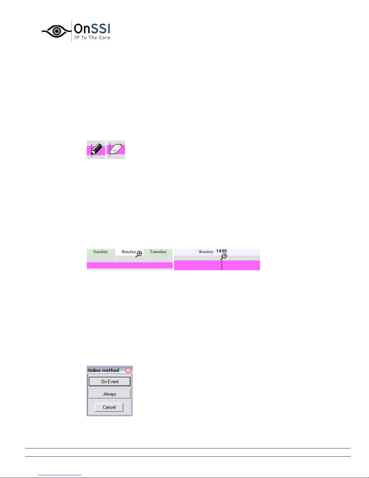
OnSSI NetDVMS Rev 6.5
Administration
• Camera/Alert Scheduler Window's Calendar Section
The Camera/Alert Scheduler window's calendar section lets you specify exact periods of
time for each option for each camera selected in the window's Camera list.
Set and Clear Modes
Depending on your selection in the Mode list, you Set or Clear periods in the calendar.
Your selection is indicated by your mouse pointer turning into either a pencil (Set) or an
eraser (Clear) when inside the calendar section.
Mouse pointer turns into pencil (Set) or
eraser (Clear) when inside calendar section
Zoom Feature
When placing your mouse pointer inside the day band in the top part of the calendar
section you get access to the calendar's zoom feature.
With the zoom feature you are able to toggle between the calendar's default seven-day
view and a single-day view.
The single-day view provides you with five-minute interval indications, allowing you to
specify periods precisely.
Calendar's zoom feature allows you to toggle between seven-day and single-day views
• How to Set or Clear Periods in the Calendar
To set or clear a period in the Camera/Alert Scheduler window's calendar section, simply
click at the required start point in the calendar, and drag to set/clear a period (depending
on whether you have selected Set or Clear in the window's Mode list).
Good to Know when You Set Online Periods
When you set an Online period, you will be asked whether you want the selected camera
to transfer images to the NetDVMS software continuously within the specified period
(Always), or only when an event occurs within the specified period (On Event).
The Online Method window where
you specify at what occasion
the camera should be online.
On-Net Surveillance Systems, Inc. | 222 Route 59, Suite 303, Suffern, NY 10901 | T: 845-369-6400 | F: 845-369-8711 | www.onssi.com | [email protected] | page 69
Page 81
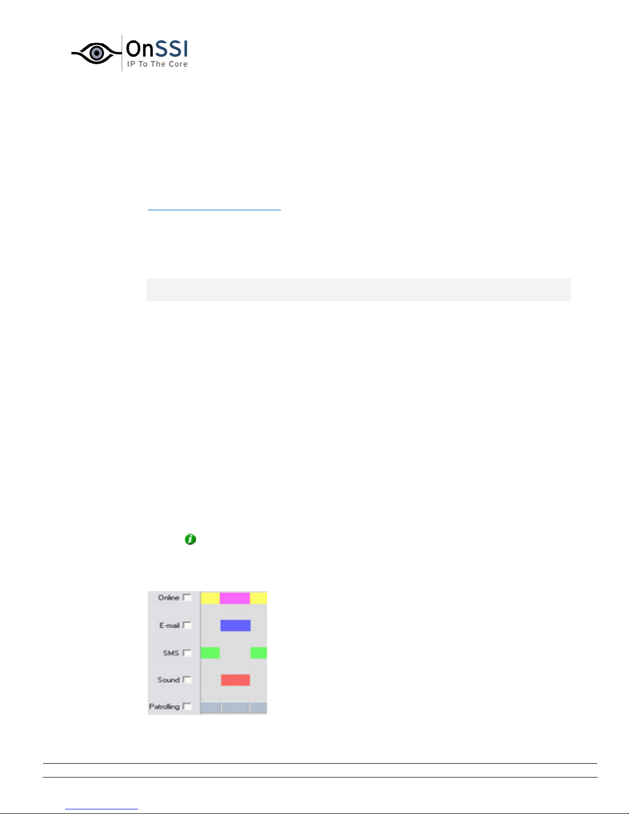
OnSSI NetDVMS Rev 6.5
Administration
If using On Event, remember to specify required start and stop events in the Start event
and Stop event lists.
Good to Know when You Set Patrolling Periods
When you set a Patrolling period, you may be able to select between several patrol
schemes. This will depend upon how many patrol schemes have been specified in the
Setup PTZ Patrolling window
You select the required patrol scheme from the Patrol scheme list, located below the
calendar section. If you set patrolling periods with different patrol schemes immediately
following each other in time, changes between patrolling schemes will be indicated by a
thin vertical line (see also Colored Bars in the following).
Note: The Patrol scheme list is only available if you have selected a PTZ camera for which
at least one patrol scheme has been set up.
.
Colored Bars
The calendar uses colored bars to indicate active periods for each option (Online, E-mail,
SMS, etc.):
• In the Online bar, active periods are indicated in either pink or yellow:
• Pink (•) indicates that the selected camera is continuously transferring
images to the NetDVMS software.
• Yellow (•) indicates that the selected camera transfers images to the
NetDVMS software when a specified event occurs.
• In the Speedup bar, active periods are indicated by olive green (•).
• In the E-mail bar, active periods are indicated in blue (•).
• In the SMS bar, active periods are indicated in green (•).
• In the Patrolling bar, active periods are indicated in gray (•). Changes between
patrolling schemes are indicated by a thin vertical line. Note that the Patrolling
bar is only available if you have selected a PTZ camera for which patrolling has
been set up.
Tip: When several patrol schemes are in use, you are able to see which patrol
scheme is used for a particular period: Click the relevant section of the gray bar;
the name of the patrol scheme in question will appear in the Patrol scheme list,
located below the calendar section.
Colored bars indicating active periods
On-Net Surveillance Systems, Inc. | 222 Route 59, Suite 303, Suffern, NY 10901 | T: 845-369-6400 | F: 845-369-8711 | www.onssi.com | [email protected] | page 70
Page 82
OnSSI NetDVMS Rev 6.5
Administration
• Camera/Alerts Scheduler Window's Copy and Paste
Buttons
Button Description
Copy
Schedule
Lets you copy the schedule displayed in the calendar section.
When used in combination with the Paste Schedule button,
you are able to quickly re-use schedules from one camera to
another.
Paste
Schedule
Lets you paste a copied schedule for use with the selected
camera.
The same copied schedule can be pasted to several cameras
simply by selecting, and pasting to, one camera after the
other.
Tip: If you want to use a schedule for all cameras, specify a
schedule for one camera, then use the Copy and Paste to All
button to copy the schedule and paste it to all cameras in one
go.
Copy and
Paste to
Lets you copy the schedule displayed in the calendar section
and paste it to all cameras in one go.
All
On-Net Surveillance Systems, Inc. | 222 Route 59, Suite 303, Suffern, NY 10901 | T: 845-369-6400 | F: 845-369-8711 | www.onssi.com | [email protected] | page 71
Page 83

OnSSI NetDVMS Rev 6.5
Administration
General Settings
General Settings Window
Note: Access to features in the Administrator application, including those described in the following, may
require administrator rights.
The General Settings window lets you manage a variety of settings, such as user rights, e-mail and SMS
settings, logging, etc.
Access: To access the General Settings window, click the General Settings... button in the
Administrator window
The General Settings window is divided into a number of sections:
• Administrator Settings
The Administrator Settings section lets you password protect access to the Administrator
application.
When the Enable Protection check box is selected, users must supply the administrator password
in order to be able to access the Administrator application, and in order to be able to use any of
the features to which access has been restricted.
.
Changing the Administrator Password
To change the administrator password, click the Change Password... button to open the Change
Password window.
When an administrator password is in use, users accessing the Administrator application, or
wishing to use protected features, must type the administrator password in the window before
access is granted.
• Manual Start Recording Settings
In the Manual start recordings settings section you can enable the possible to manually start
recording in the NetGuard-EVS.
Select the check box Enable manual start recording to enable manually start of recording.
In the Default duration of manual recording [secs.]: field you can specify the number of seconds
the recording should last. Note that the minimum number of seconds you can specify is 30.
The Maximum duration of manual recording [secs.]: field is reserved for future usage.
On-Net Surveillance Systems, Inc. | 222 Route 59, Suite 303, Suffern, NY 10901 | T: 845-369-6400 | F: 845-369-8711 | www.onssi.com | [email protected] | page 72
Page 84
OnSSI NetDVMS Rev 6.5
Administration
• Patrolling Settings
Note: Settings in this section are relevant only if you are using PTZ cameras for which patrolling
has been set up.
The regular patrolling of PTZ cameras may be interrupted, either manually or when a particular
event occurs. The Patrolling settings section lets you specify how many seconds should pass
before the regular patrolling is resumed after a manual or event-based interruption. Default is 30
seconds.
The settings in this section will apply for all installed PTZ cameras.
IMPORTANT: Users of the NetGuard-EVS are—in addition to manual control—able to stop a
selected PTZ camera's patrolling entirely. This takes place through a context menu in the
NetGuard-EVS view. Therefore, for NetGuard-EVS users, the number of seconds specified in the
Patrolling settings section does only apply when users manually control a PTZ camera; not when
users stop a PTZ camera's patrolling entirely. When NetGuard-EVS users stop a PTZ camera's
patrolling entirely, the camera's patrolling will resume only when the NetGuard-EVS user selects
to resume it.
Tip: PTZ patrolling for individual PTZ cameras is configured in the Setup PTZ Patrolling window.
• Logfile Settings
The Logfile Settings section lets you specify where to keep the general log files containing
information about activity in the Administrator and recording server, and how long for.
Separate log files are generated for the Administrator and recording server service.
Logfile Path
By default, the Administrator and recording server log files are stored in the folder containing the
NetDVMS software.
To specify another location for your log files, type the path to the required folder in the Logfile
Path field, or click the browse button next to the field to browse to the required folder.
Days to Log
A new log file is created every day. A log file older than the number of days specified in the Days
to log field is automatically deleted. By default, the log file will be stored for five days.
To specify another number of days, simply overwrite the value in the Days to log field.
The current day's activity is always logged, even with a value of 0 in the Days to log field. The
maximum number of days to log is 9999.
Tip: Read more about NetDVMS logging in About Logging.
On-Net Surveillance Systems, Inc. | 222 Route 59, Suite 303, Suffern, NY 10901 | T: 845-369-6400 | F: 845-369-8711 | www.onssi.com | [email protected] | page 73
Page 85

OnSSI NetDVMS Rev 6.5
Administration
• Event Recording Settings
As opposed to the general log files, which contain information about activity on the surveillance
system itself, event log files contain information about registered events (for more information
about events, see About Input, Events & Output ...
The Event Recording Settings section lets you specify where to keep event log files, and for how
long.
Event log files should be viewed using the NetGuard-EVS
).
or Viewer:
• NetGuard-EVS: In the Browse tab's Alerts section, select the required event, then click
the Get List button to see when the event in question was detected.
• Viewer: Select the Viewer’s Alarm Overview control panel, then click the Events button
to view the events log.
Path
By default, event log files are stored in the folder containing the NetDVMS software.
To specify another location for your log files, type the path to the required folder in the Path field,
or click the browse button next to the field to browse to the required folder.
Days to Keep
A new event log file is created every day. Event log files older than the number of days specified
in the Days to keep field are automatically deleted. By default, event log files will be stored for
five days.
To specify another number of days, simply overwrite the value in the Days to keep field.
The current day's activity is always logged, even with a value of 0 in the Days to keep field. The
maximum number of days to log is 9999.
Tip: Read more about NetDVMS logging in About Logging.
On-Net Surveillance Systems, Inc. | 222 Route 59, Suite 303, Suffern, NY 10901 | T: 845-369-6400 | F: 845-369-8711 | www.onssi.com | [email protected] | page 74
Page 86
• Advanced
The Advanced section lets you specify a number of additional settings:
Check Box Description
OnSSI NetDVMS Rev 6.5
Administration
Don't send email on camera
failures
Don't send SMS
on camera
failures
Start cameras
on remote live
requests
Create default
schedule for
new cameras
If selected, no e-mail alerts will be sent if NetDVMS loses contact with a camera.
Otherwise, e-mail alerts will, provided the e-mail alert feature has been enabled in
the E-Mail setup window, automatically be sent if NetDVMS loses contact with a
camera, regardless of any e-mail alerts periods defined in the Camera/Alert
Scheduler window.
If selected, no SMS alerts will be sent if NetDVMS loses contact with a camera.
Otherwise, SMS alerts will, provided the SMS alert feature has been enabled in the
SMS settings window, automatically be sent if NetDVMS loses contact with a
camera, regardless of any e-mail alerts periods defined in the Camera/Alert
Scheduler window.
Cameras may be stopped, for example because they have reached the end of an
online schedule, in which case NetGuard and NetGuard-EVS users will not be able
to view live images from the cameras.
However, if Start cameras on remote live requests is selected, NetGuard and
NetGuard-EVS users will be able to start the camera in order to view live video
from the camera.
If selected (default), a schedule specifying that the camera is always online (i.e.
transferring images to NetDVMS) will automatically be created in the Camera/Alert
Scheduler window. The automatically created schedule can be edited manually at
any time.
If not selected, no schedule will automatically be created; meaning that the camera
will not automatically be transferring images to NetDVMS. When required,
schedules can be added manually in the Camera/Alert Scheduler window.
• Email Settings
Clicking the Email Settings... button opens the E-Mail setup window, in which you enable and
configure the use of e-mail alerts.
• SMS Settings
Clicking the Sms Settings... button opens the SMS settings window
configure the use of SMS (mobile phone text message) alerts. Note: Use of the SMS alert feature
requires that an external Siemens TC-35 GSM modem has been attached to a serial port on the
computer running the NetDVMS software.
On-Net Surveillance Systems, Inc. | 222 Route 59, Suite 303, Suffern, NY 10901 | T: 845-369-6400 | F: 845-369-8711 | www.onssi.com | [email protected] | page 75
, in which you enable and
Page 87
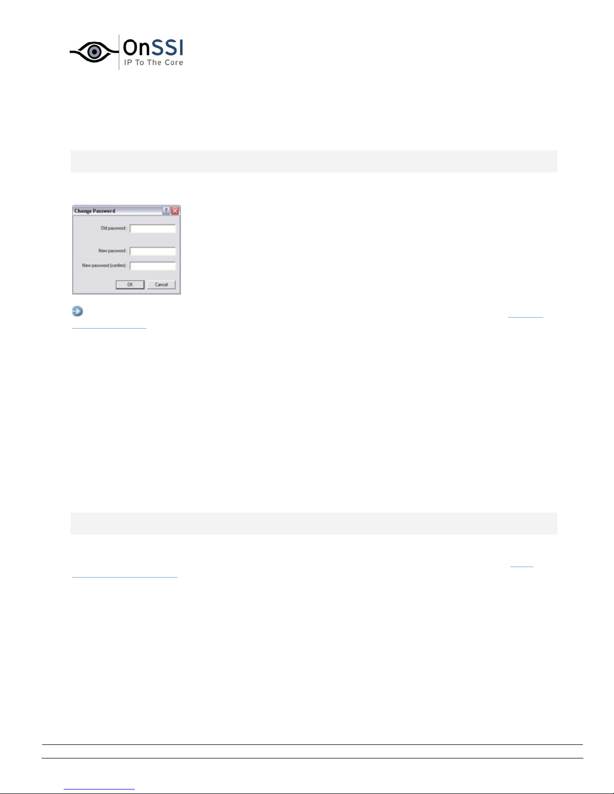
OnSSI NetDVMS Rev 6.5
Administration
Change Password Window
Note: Access to features in the Administrator application, including those described in the following, may
require administrator rights.
The Change Password window lets you change the administrator password for your NetDVMS solution.
Access: To access the Change Password window, click the Change Password... button in the General
Settings window.
• How to Change the Administrator Password
To change the administrator password, do the following:
1. Specify the current administrator password in the Old password field
2. Specify the new administrator password in the New password field
3. Repeat the new administrator password in the New password (confirm) field
4. Click OK.
E-Mail Setup Window
Note: Access to features in the Administrator application, including those described in the following, may
require administrator rights.
The E-Mail setup window lets you enable and configure the use of e-mail alerts. Such e-mail alerts can
automatically be sent to one or more recipients when motion is detected or specific events (see
Input, Events & Output ...) occur.
By default, SMTP (Simple Mail Transfer Protocol) is used when sending e-mail alerts. Compared with
other mail transfer methods, SMTP has the advantage that you will avoid automatically triggered
warnings from your e-mail client when an e-mail alert is to be sent. Such automatically triggered
warnings may otherwise inform you that your e-mail client is trying to automatically send e-mail
messages on your behalf.
About
On-Net Surveillance Systems, Inc. | 222 Route 59, Suite 303, Suffern, NY 10901 | T: 845-369-6400 | F: 845-369-8711 | www.onssi.com | [email protected] | page 76
Page 88
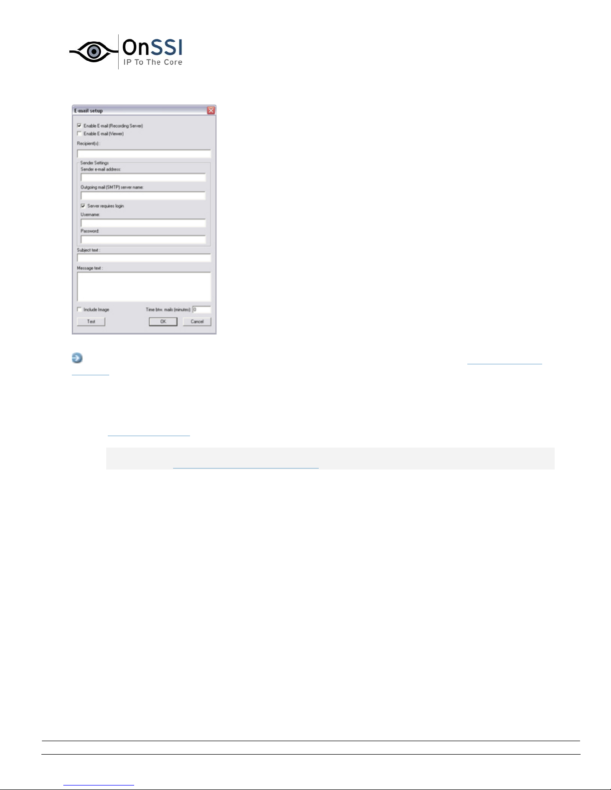
OnSSI NetDVMS Rev 6.5
Administration
The E-mail setup window
Access: To access the E-Mail setup window, click the Email Settings... button in the General Settings
window.
• Enabling E-Mail Alerts
You enable the use of e-mail alerts separately for the Recording Server and—if applicable—the
Viewer application:
Note: When enabling e-mail alerts, also consider the e-mail alert schedules configured for each
camera in the Camera/Alert Scheduler window.
• Enable E-Mail (Recording Server):
Select check box to enable the use of e-mail alerts when the Recording Server is running.
E-mail alerts will then be sent when the following conditions apply:
o the Recording Server is running
o motion is detected or an event, for which the sending of an e-mail alert has been
defined, occurs
o motion is detected or the event occurs within a period of time for which an e-mail
alert schedule has been defined
• Enable E-Mail (Viewer):
Select check box to enable the use of e-mail alerts in the Viewer application. In effect,
this will display the E-Mail Report button in the Viewer's toolbar, enabling users to send
evidence via e-mail. If you clear the check box, the E-Mail Report button will not be
available in the Viewer's toolbar.
Use of the e-mail feature is only possible when the Viewer is run on the surveillance
system server itself; not in a Viewer exported with video evidence.
On-Net Surveillance Systems, Inc. | 222 Route 59, Suite 303, Suffern, NY 10901 | T: 845-369-6400 | F: 845-369-8711 | www.onssi.com | [email protected] | page 77
Page 89

OnSSI NetDVMS Rev 6.5
Administration
• Specifying Recipients
You specify the e-mail addresses to which e-mail alerts should be sent in the Recipient(s) field.
If specifying more than one e-mail address, separate the e-mail addresses with semicolons
(example: [email protected];[email protected];[email protected]).
Note: If e-mail alerts are enabled for the Viewer, the content you specify in the Recipient(s) field
will appear as the default value in the Viewer's dialog for sending evidence via e-mail. Users will
be able to overwrite this default value.
• Specifying Sender Settings
Specify sender information in the following fields:
• Sender e-mail address: Type the e-mail address you wish to appear as the sender of
the e-mail alert.
• Outgoing mail (SMTP) server name: Type the name of the SMTP server which will be
used for sending the e-mail alerts.
• Server requires login: Select check box if a user name and password is required to use
the SMTP server.
• Username: Field available only when Server requires login is selected. Type the user
name required for using the SMTP server.
• Password: Field available only when Server requires login is selected. Type the password
required for using the SMTP server.
• Specifying Default Subject and Message Texts
Specify default subject and message texts in the following fields:
• Subject text: Specify required subject text for e-mail alerts.
• Message text: Specify required message text for e-mail alerts. Note that camera
information as well as date and time information is automatically included in e-mail alerts.
Note: If e-mail alerts are enabled for the Viewer, the content you specify in the Subject text and
Message text fields will appear as default values in the Viewer's dialog for sending evidence via e-
mail. Users will be able to overwrite these default values.
On-Net Surveillance Systems, Inc. | 222 Route 59, Suite 303, Suffern, NY 10901 | T: 845-369-6400 | F: 845-369-8711 | www.onssi.com | [email protected] | page 78
Page 90
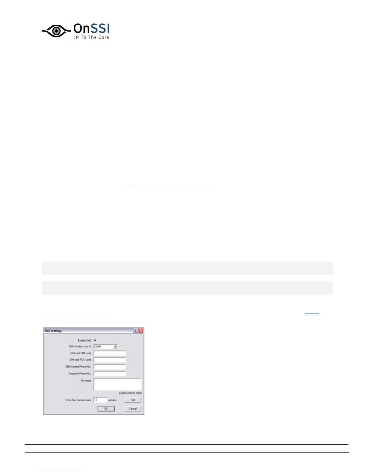
OnSSI NetDVMS Rev 6.5
Administration
• Specifying Image and Interval Options
You are able to specify whether e-mail alerts should include images, and how much time should
pass between alerts per camera:
• Include Image: Select check box to include images in e-mail alerts. When selected, a
JPG image from the time the triggering event occurred will be attached to each alert email.
• Time btw. mails (minutes): Specify required minimum time (in minutes) to pass
between the sending of each e-mail alert per camera.
Examples: If specifying 5, a minimum of five minutes will pass between the sending of
each e-mail alert per camera, even if motion is detected or events occur in between. If
specifying 0, e-mail alerts will be sent each time motion is detected or events occur,
potentially resulting in a very large number of e-mail alerts being sent. If using the value
0, you should therefore consider the motion detection sensitivity configured for each
camera in the Adjust Motion Detection window
.
• Testing Your E-Mail Alert Configuration
You are able to test your e-mail alert configuration by clicking the Test button. This will send a
test e-mail to the specified recipients.
If Include Image is selected, the test e-mail will have a test JPG image attached.
SMS Settings Window
Note: Access to features in the Administrator application, including those described in the following, may
require administrator rights.
Note: Use of the SMS (mobile phone text message) alert feature requires that an external Siemens TC-
35 GSM modem has been attached to a serial port on the computer running the NetDVMS software.
The SMS settings window lets you enable and configure the use of SMS alerts. Such SMS alerts can
automatically be sent to one or more recipients when motion is detected or specific events (see
Input, Events & Output ...) occur.
The SMS settings window
About
On-Net Surveillance Systems, Inc. | 222 Route 59, Suite 303, Suffern, NY 10901 | T: 845-369-6400 | F: 845-369-8711 | www.onssi.com | [email protected] | page 79
Page 91

OnSSI NetDVMS Rev 6.5
Administration
Access: To access the SMS settings window, click the Sms Settings... button in the General Settings
window.
• Enabling SMS Alerts
You enable the use of SMS alerts by selecting the Enable SMS check box.
Note: When enabling the use of SMS alerts, also consider the SMS alert schedules configured for
each camera in the Camera/Alert Scheduler window.
• Specifying SMS Alert Settings
Having selected the Enable SMS check box, specify SMS alert settings in the following fields:
• GSM modem con. to: Select port connecting the computer running NetDVMS to the GSM
modem.
• SIM card PIN code: Specify PIN code for the SIM card inserted in the GSM modem.
• SIM card PUK code: Specify PUK code for the SIM card inserted in the GSM modem.
• SMS Central Phone No.: Specify the number of the SMS central to which the GSM
modem should connect in order to send an SMS.
• Recipient Phone No.: Specify the number of the telephone to which SMS alerts should
be sent.
• Message: Specify required message text for SMS alerts. Message text must be no longer
that 100 characters, and must only contain the following characters: a-z, A-Z, 0-9 as well
as commas (,) and full stops (.). Note that camera information as well as date and time
information is automatically included in SMS alerts.
• Time btw. transmissions: Specify required minimum time (in minutes) to pass between
the sending of each SMS alert per camera.
Examples: If specifying 5, a minimum of five minutes will pass between the sending of
each SMS alert per camera, even if motion is detected or events occur in between. If
specifying 0, SMS alerts will be sent each time motion is detected or events occur,
potentially resulting in a very large number of SMS alerts being sent. If using the value 0,
you should therefore consider the motion detection sensitivity configured for each camera
in the Adjust Motion Detection window
.
• Testing Your SMS Alert Configuration
You are able to test your SMS alert configuration by clicking the Test button. This will send a test
SMS to the specified recipients.
Note: If the Recording Server service is running, the button will not be available. To make the
button available, pause the Recording Server service by clicking the Administrator window's
Service Manager button, then clicking the Pause button.
IMPORTANT: No video or audio will be recorded while the Recording Server service is paused.
On-Net Surveillance Systems, Inc. | 222 Route 59, Suite 303, Suffern, NY 10901 | T: 845-369-6400 | F: 845-369-8711 | www.onssi.com | [email protected] | page 80
Page 92
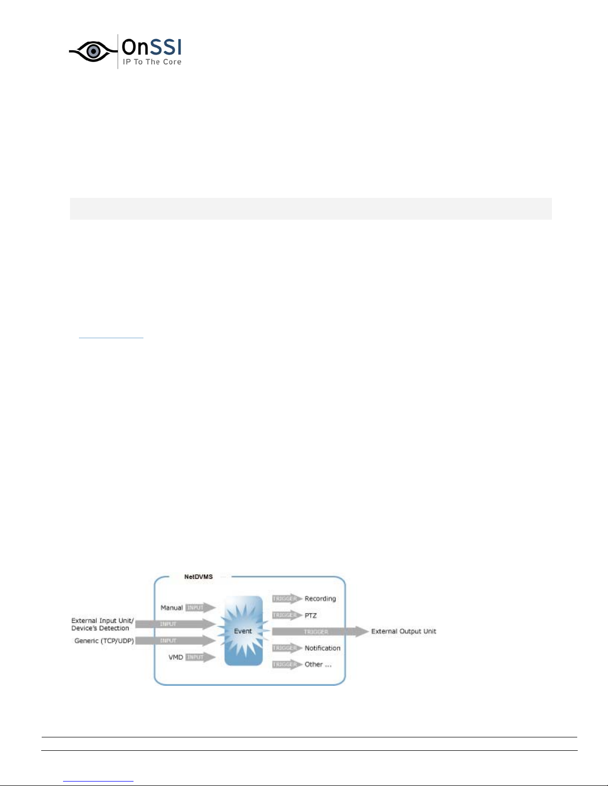
OnSSI NetDVMS Rev 6.5
Administration
Input, Events & Output
About Input, Events & Output ...
Note: Access to features in the Administrator application, including those described in the following, may
require administrator rights.
Input received from a wide variety of sources can be used to generate events in NetDVMS.
Events can in turn be used for automatically triggering actions in NetDVMS, such as starting or stopping
recording on cameras, triggering e-mail or SMS notifications, making PTZ cameras move to specific
preset positions, making images automatically appear on NetMatrix recipients, etc. Events can also be
used for activating output.
Output units can be attached to output ports on many devices, allowing you to activate lights, sirens,
etc. from NetDVMS. Such external output can be activated automatically by events, or manually from the
/ NetGuard-EVS
.
Types of Events
You specify which types of input should generate which types of events. Basically, four types of events
exist:
• On many devices you are able to attach external input units to input ports on the device. Events
based on input from such external input units—typically sensors attached to doors, windows,
etc.—are called input events. Some devices also have their own capabilities for detecting
motion, for detecting moving and/or static objects, etc. (typically configured in the devices' own
software), in which case you are also able to use such detections from the device as input events.
• Input may also be received in the form of TCP or UDP data packages, which can be analyzed and,
if matching specified criteria, used to generate events. Such events are called generic events.
• Events may be based on NetDVMS detecting motion on a camera. Such events are called VMD
(i.e. Video Motion Detection) events.
• Finally, events may be generated manually by users clicking custom-made buttons in NetDVMS.
Such buttons are called event buttons.
Events—whether based on manual input, based on input from external input units/devices' own detections, based on received TCP/UDP data
packages, or based on NetDVMS-detected motion—can trigger a wide variety of actions.
On-Net Surveillance Systems, Inc. | 222 Route 59, Suite 303, Suffern, NY 10901 | T: 845-369-6400 | F: 845-369-8711 | www.onssi.com | [email protected] | page 81
Page 93

OnSSI NetDVMS Rev 6.5
Administration
Specifying Input, Events and Output
In NetDVMS, your main entry point for configuration of input, event and output handling is the
Administrator window
• By clicking the Administrator window's I/O Setup... button, you open the I/O Setup window, in
which you are able to specify each individual
• By clicking the Administrator window's Event Buttons... button, you open the Event Buttons
window
activity.
• By clicking the Administrator window's Generic Events... button, you open the Generic Events
window
• By clicking the Administrator window's I/O Control... button, you open the I/O Control window, in
which you are able to
example, specify that when motion is detected on a camera (typically specified as a VMD event) a
siren should automatically sound (output). If you want users to be able to manually activate
output when operating specific cameras, you specify this in the
[Camera Name] window.
Note: Before you specify use of external input and output units on a device, verify that sensor operation
is recognized by the device. Most devices are capable of showing this in their configuration interfaces, or
via CGI script commands. Also check the OnSSINetDVMS release notes to verify that input and output
controlled operations are supported for the device and firmware used.
Note: If you are using several NetDVMS servers in your surveillance solution setup, input and output on
a specific device should be defined on one of the servers only. Do not define the same input or output on
the same device on several servers. This applies even for dedicated I/O devices (see also Using Dedicated
I/O Devices).
:
input event, VMD event and output.
, in which you are able to specify event buttons for manually triggering events-controlled
, in which you are able to specify generic events.
associate specific events with specific output. This way you can, for
Output Settings for [Device Name]
On-Net Surveillance Systems, Inc. | 222 Route 59, Suite 303, Suffern, NY 10901 | T: 845-369-6400 | F: 845-369-8711 | www.onssi.com | [email protected] | page 82
Page 94

OnSSI NetDVMS Rev 6.5
Administration
Using Dedicated I/O Devices
In addition to IP video camera devices and IP video encoder devices it is possible to add a number of
dedicated I/O (input/output) devices to NetDVMS (see
I/O devices are supported, refer to the release note.
When such I/O devices are added, input on the I/O devices can be used to generate events in NetDVMS,
and events in NetDVMS can be used for activating output on the I/O devices. This means that I/O devices
can be used in your events-based system setup in the same way as a camera.
Note: When using some I/O devices it is necessary for the surveillance system to regularly check the
state of the devices' input ports in order to detect whether input has been received. Such state checking
at regular intervals is called polling. The interval between state checks, called a polling frequency, is
specified in the Advanced window. For such I/O devices, the polling frequency should be set to the lowest
possible value (one tenth of a second between state checks). For information about which I/O devices
require polling, see the release note.
How to Add a Device). For information about which
I/O Setup
I/O Setup Window
Note: Access to features in the Administrator application, including those described in the following, may
require administrator rights.
The I/O Setup window lets you define input events, VMD (Video Motion Detection) events and output for
devices on your surveillance system.
When events occur, they can trigger one or more actions:
• Input events occur when input from an external input unit is received on a device's input port, for
example when an external sensor detects that a door is opened. Some devices also have their
own capabilities for detecting motion, for detecting moving and/or static objects, etc. (configured
in the devices' own software; typically by accessing a browser-based configuration interface on
the device's IP address), in which case such detections from the device can also be used as input
events.
• VMD events occur when NetDVMS detects motion on a particular camera.
• Outputs are used for activating external output units, for example for switching on lights or
sounding a siren.
The I/O Setup window is used for defining which input events, VMD events and outputs should be
available on your system.
Input and VMD events can be used for triggering outputs or for triggering various actions on the
surveillance system itself, such as for starting or stopping cameras (configured in the Camera/Alert
Scheduler window) or for moving a PTZ camera to a particular preset position (configured in the Event
window (for PTZ preset positions on event)
Once you have defined input events, VMD events and outputs, you are able to associate specific input
events or VMD events with specific outputs in the I/O Control win
).
dow, so that, for example, lights are
On-Net Surveillance Systems, Inc. | 222 Route 59, Suite 303, Suffern, NY 10901 | T: 845-369-6400 | F: 845-369-8711 | www.onssi.com | [email protected] | page 83
Page 95
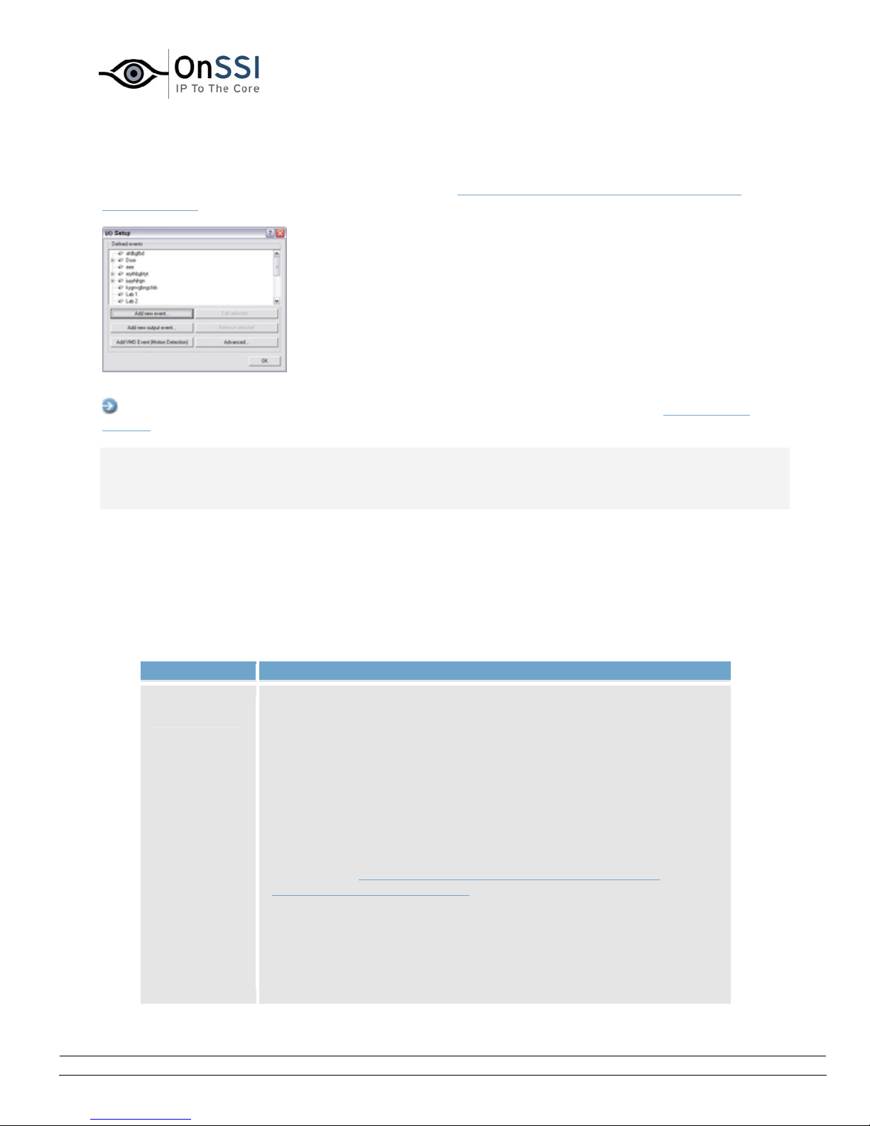
OnSSI NetDVMS Rev 6.5
Administration
switched on when a door is opened or when motion is detected on a camera. Outputs may also be
triggered by motion detection on a specific camera—even without a defined VMD event—or manually
through the NetGuard-EVS; both are configured in the Output Settings for [Device Name] [Camera
Name] window.
The I/O Setup window
Access: You access the I/O Setup window by clicking the I/O Setup... button in the Administrator
window.
Note: Before you specify inputs and outputs for a device, verify that sensor operation is recognized by
the device. Most devices are capable of showing this in their configuration interfaces, or via CGI script
commands. Also check NetDVMS release notes to verify that input and output controlled operations are
supported for the device and firmware used.
• I/O Setup Window's Defined Events List and Buttons
The I/O Setup window features a Defined events list, in which input, output and VMD (Video
Motion Detection) events defined for each device are listed.
The window furthermore features a number of buttons for use when adding and configuring the
events:
Button Description
Add new
event...
Used for defining input events on the device selected in the Defined
events list.
Depending on the type of device, you may be able to define one or
more input events on the device. Some devices do not support
input/output at all. Refer to the release notes for device-specific
information.
Devices Capable of Handling One Input Event Only
If the device is capable of handling one input event only, the button
will open the Add New Event window (for devices capable of
handling one input event only), in which you define the input event,
and any e-mail or SMS alerts to be associated with it.
If you have already defined an input event on a device capable of
handling one input event only, the Add new event... button will not
be available when the device is selected in the Defined events list.
On-Net Surveillance Systems, Inc. | 222 Route 59, Suite 303, Suffern, NY 10901 | T: 845-369-6400 | F: 845-369-8711 | www.onssi.com | [email protected] | page 84
Page 96

OnSSI NetDVMS Rev 6.5
Administration
However, if you click the plus sign next to the device in the Defined
events list, and select the defined input event, the Add new event...
button becomes available for defining timer events (see Timer
Events in the following).
Devices Capable of Handling Several Input Events
If the device is capable of handling more than one input event, the
button will open the Multiple Input Events window, in which you
define which of the device's possible input events should be enabled,
and whether any alerts should be associated with enabled input
events.
Timer Events
When you click the plus sign next to the device in the Defined events
list, and select a defined input event, the Add new event... button
becomes available for defining timer events: When clicked, the
button will open the New Timer window, in which you are able to
specify the settings for timer events.
Timer events are separate events, triggered by the input event
under which they are defined. Timer events occur a specified
number of seconds or minutes after the input event under which
they are defined.
Timer events may be used for a wide variety of purposes; the
following are examples only:
• A camera starts based on an input event, e.g. when a door
is opened, a timer event stops the camera after 15 seconds
• A camera starts and the lights are switched on based on an
input event, e.g. when a door is opened, a timer event stops
the camera after one minute, and another timer event
switches the lights off after two minutes
Add new
output
event...
Add VMD
Event
(Motion
Detection)
Opens the Add New Output window, in which you are able to specify
a name for the required output event, which of the device's output
ports to use, and how long to keep the output for.
Lets you add a VMD (Video Motion Detection) event to the device
selected in the Defined Events list.
VMD events are events triggered when NetDVMS detects motion on
a specific camera, based on the motion detection settings defined in
the Adjust Motion Detection window.
Note: In addition to NetDVMS's motion detection, some devices also
have their own capabilities for detecting motion (configured in the
devices' own software; typically by accessing a browser-based
configuration interface on the device's IP address). Events based on
motion detected on a device itself are not VMD Events; they are
On-Net Surveillance Systems, Inc. | 222 Route 59, Suite 303, Suffern, NY 10901 | T: 845-369-6400 | F: 845-369-8711 | www.onssi.com | [email protected] | page 85
Page 97

OnSSI NetDVMS Rev 6.5
Administration
input events, since they are based on input from the device.
VMD events can be used just like regular input events. For example,
a PTZ (Pan/Tilt/Zoom) camera could move to a specific preset
position when a VMD event occurs.
Only one VMD event can be defined per camera.
In order to avoid the risk of an excessively high number of VMD
events being generated, a VMD event cannot occur more frequently
than every five seconds.
The Add VMD Event (Motion Detection) button works slightly
different depending on whether the selected device is a singlecamera device or a multi-camera device, such as a video encoder:
• Single-camera devices: Clicking the Add VMD Event
(Motion Detection) button will instantly add a VMD event to
the selected device, provided a VMD event has not already
been defined for the device.
• Multi-camera devices: Clicking the Add VMD Event (Motion
Detection) button will open a simple dialog in which you
select the required camera. This way you are able to define
a VMD event for each camera on a multi-camera device.
Edit
selected...
Remove
selected
Advanced...
Lets you edit the settings for an item selected in the Defined events
list.
For devices capable of handling a single input event only, the button
will open the Edit Event window (for editing input events).
For devices capable of handling several input events, the button will
open the Multiple Input Events window.
If the selected item is a timer event, the button will open the New
Timer window.
If the selected item is an output, the button will open the Edit
Output window.
Lets you remove an event selected in the Defined events list.
Note: The selected event will be removed without further warning.
Opens the Advanced window
, in which you are able to specify
network settings to be used in connection with event handling:
which ports to use for FTP, alerts and SMTP input/output events as
well as which polling frequency to use on devices requiring polling.
On-Net Surveillance Systems, Inc. | 222 Route 59, Suite 303, Suffern, NY 10901 | T: 845-369-6400 | F: 845-369-8711 | www.onssi.com | [email protected] | page 86
Page 98

OnSSI NetDVMS Rev 6.5
Administration
Add New Event Window (Devices With One Input Event)
Note: Access to features in the Administrator application, including those described in the following, may
require administrator rights.
The Add New Event window (for devices capable of handling one input event only) lets you specify the
settings for an input event on devices capable of handling one input event only.
The Add New Event window (for
devices capable of handling one
input event only)
Access: You access the Add New Event window (for devices capable of handling one input event only)
by selecting the required device and clicking the Add new event... button in the I/O Setup window. Note
that this only applies when the selected device is capable of handling a single input event only. Some
devices are capable of handling several input events, in which case a different window, the Multiple Input
Events window, will open when the Add new event... button is clicked.
Note: Before you specify input events for a device, verify that sensor operation is recognized by the
device. Most devices are capable of showing this in their configuration interfaces, or via CGI script
commands. Also check the NetDVMS release note to verify that input-controlled operations are supported
for the device and firmware used.
On-Net Surveillance Systems, Inc. | 222 Route 59, Suite 303, Suffern, NY 10901 | T: 845-369-6400 | F: 845-369-8711 | www.onssi.com | [email protected] | page 87
Page 99
• Add New Event Window's Fields
The Add New Event window (for devices capable of handling one input event only) contains the
following fields:
Field, Check
Box
Description
OnSSI NetDVMS Rev 6.5
Administration
External sensor
connected to
Sensor
connected
through
Event occurs
when input
goes
External event
name
Read-only field, displaying the name of the device on which the input event is
defined.
Lets you select which of the device's input ports the sensor used for the input event
is connected to.
Lets you select whether input event should be triggered when the signal on the
input sensor rises or falls:
• Low: Trigger input event when the signal on the sensor is falling
• High: Trigger input event when the signal on the sensor is rising
For exact information about what constitutes a falling and a rising signal
respectively, refer to documentation for the sensor and device in question.
Lets you specify a name for the input event.
Note: Event names must not contain the following characters: < > & ' " \ / : * ? | [
]
Note: Some camera devices only support event names of a certain length and/or
with a certain structure. Refer to the camera's documentation for exact details.
Send e-mail if
this event
occurs
Select check box to send an e-mail alert when the input occurs.
Note: In order to be able to use e-mail alerts, the e-mail alert feature must have
been set up in the E-Mail setup window.
Include image
from camera
Available only if the Send e-mail if this event occurs check box is selected.
Select check box to include an image, recorded at the time the input event is
triggered, in the e-mail alert, then select the required camera in the list next to the
check box.
Send SMS if
this event
occurs
Select check box to send an SMS alert when the input occurs.
Note: In order to be able to use SMS alerts, the SMS alert feature must have been
set up in the SMS settings window.
On-Net Surveillance Systems, Inc. | 222 Route 59, Suite 303, Suffern, NY 10901 | T: 845-369-6400 | F: 845-369-8711 | www.onssi.com | [email protected] | page 88
Page 100
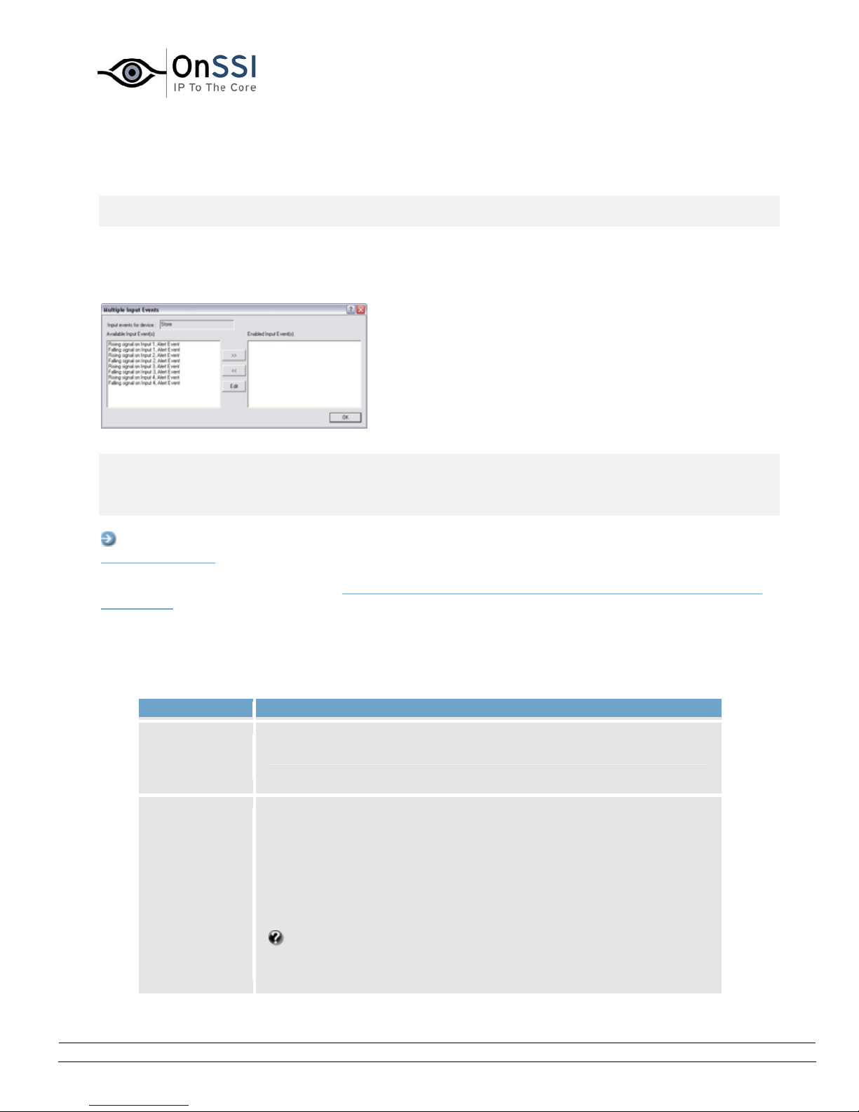
OnSSI NetDVMS Rev 6.5
Administration
Multiple Input Events Window
Note: Access to features in the Administrator application, including those described in the following, may
require administrator rights.
The Multiple Input Events window is used for devices capable of handling several input events. It lets you
define which of the device's possible input events should be enabled, and whether any alerts should be
associated with enabled input events.
The Multiple Input Events window
Note: Before you specify input events for a device, verify that sensor operation is recognized by the
device. Most devices are capable of showing this in their configuration interfaces, or via CGI script
commands. Also check NetDVMS release notes to verify that input and output controlled operations are
supported for the device and firmware used.
Access: You access the Multiple Input Events window by clicking the Add new event... button in the
I/O Setup window. Note that this only applies when the device selected in the I/O Setup window is
capable of handling several input events. Some devices are capable of handling a single input event only,
in which case a different window, the Add New Event wi
ndow (for devices capable of handling one input
event only), will open when the Add new event... button is clicked.
• Multiple Input Events Window's Fields and Buttons
The Multiple Input Events window contains the following fields and buttons:
Field Description
Input
events for
device
Available
Input
Event(s)
Read-only field, displaying the name of the device on which the
input events are defined.
Lists available input events for the device, typically with an input
event for rising and falling signals on each of the device's input
ports.
For exact information about what constitutes the various input
events, refer to documentation for the sensors and device in
question.
My list contains event related to motion and/or object
detection; what's this? Some devices have their own capabilities
for detecting motion and/or moving/static objects. A motion or
On-Net Surveillance Systems, Inc. | 222 Route 59, Suite 303, Suffern, NY 10901 | T: 845-369-6400 | F: 845-369-8711 | www.onssi.com | [email protected] | page 89
 Loading...