

Page 1
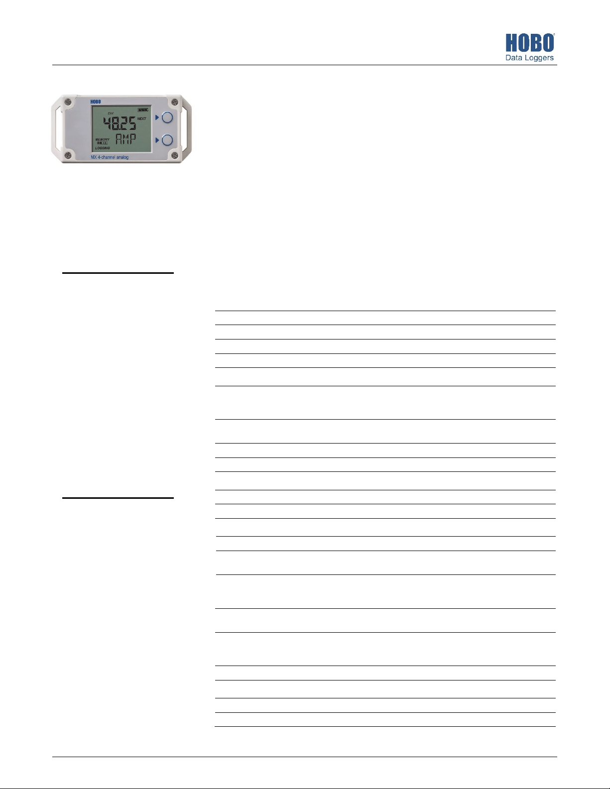
HOBO® MX Analog/Temp/RH/Light (MX1104) and
MX 4-Channel Analog (MX1105) Data Logger Manual
The HOBO MX Analog/Temp/RH/Light (MX1104) and HOBO MX 4-Channel Analog (MX1105)
data loggers measure and transmit data wirelessly from indoor environments to a mobile
device or computer using Bluetooth® Low Energy (BLE) technology. The MX1104 model has
integrated temperature, relative humidity (RH), and light intensity sensors and one analog input
while the MX1105 model has four analog inputs. Both models support a wide variety of
external sensors (sold separately), including self-describing temperature, split-core AC current
transformer, 4-20 mA input, and DC voltage input sensors. The self-describing sensors are
MX1105 Model Shown
HOBO MX1104 and
MX1105 Data Loggers
designed with integrated strain relief for a secure connection to the loggers and are
automatically detected by the HOBOconnect® app for easy setup. Using the app, you can
configure the loggers, read out and view data, and export the data for further analysis. The
loggers can calculate minimum, maximum, average, and standard deviation statistics and can
also be configured to trip audible or visual alarms at thresholds you specify. In addition, both
loggers support burst logging in which data is logged at a different interval when sensor
readings are above or below certain limits. These compact loggers also have built-in LCD
screens to display current sensor readings, logging status, battery use, memory consumption,
and more.
Models:
• Analog/Temp/RH/Light
(MX1104)
• 4-Channel Analog
(MX1105)
Included Items:
• Tie wraps
• Two AAA 1.5 V alkaline
batteries (installed)
Required Items:
• HOBOconnect app
• Mobile device with
Bluetooth and iOS,
iPadOS®, or Android™, or a
Windows computer with a
native BLE adapter or
supported BLE dongle
Specifications
Temperature Sensor (MX1104)
Range -20° to 70°C (-4° to 158°F)
Accuracy ±0.20°C from 0° to 50°C (±0.36°F from 32° to 122°F)
Resolution 0.002°C at 25°C (0.004°F at 77°F)
Drift <0.1°C (0.18°F) per year
RH Sensor* (MX1104)
Range 0% to 100% at -20° to 70°C (-4° to 158°F); exposure to conditions
Accuracy ±2.5% from 10% to 90% (typical) to a maximum of ±3.5% including
Resolution 0.01%
Drift <1% per year typical
Response Time (MX1104)
Temperature 11 minutes in air moving 1 m/s (2.2 mph)
RH 30 seconds to 90% in airflow of 1 m/s (2.2 mph)
Light Sensor (MX1104)
Range 0 to 167,731 lux (15,582 lum/ft2)
Accuracy ±10% typical for direct sunlight (see Light Measurement on page 4 for
Logger with
Cable Type
Measurement
Range
Accuracy ±0.001 mA
Resolution 0.3 µA 40 µV 80 µV 160 µV 384 µV
Logger
Operating Range -20° to 70°C (-4° to 158°F)
Radio Power 1 mW (0 dBm)
SD-MA-420 or
CABLE-420mA
0 to 20.1 mA 0 to 2.5 V 0 to 5.0 V 0 to 10 V 0 to 24 V
±0.2% of
reading
above 95% may temporarily increase the maximum RH sensor error
by an additional 1%
hysteresis at 25°C (77°F); below 10% and above 90% ±5% typical
more details)
SD-VOLT-2.5
or CABLE-2.5STEREO
±0.1 mV
±0.1% of
reading
SD-VOLT-05
or CABLEADAP5
±0.2 mV
±0.3% of
reading
SD-VOLT-10
or CABLEADAP10
±0.4 mV
±0.3% of
reading
SD-VOLT-24
or CABLEADAP24
±1.0 mV
±0.3% of
reading
23968-H
Find Quality Products Online at: [email protected]
www.GlobalTestSupply.com
Page 2
HOBO MX Analog/Temp/RH/Light (MX1104) and MX 4-Channel Analog (MX1105) Manual
Specifications (continued)
Transmission Range Approximately 30.5 m (100 ft) line-of-sight
Wireless Data Standard Bluetooth Low Energy (Bluetooth Smart)
Logging Rate 1 second to 18 hours
Logging Modes Fixed interval (normal, statistics) or burst
Memory Modes Wrap when full or stop when full
Start Modes Immediate, push button, date & time, or next interval
Stop Modes When memory full, push button, date & time, or after a set logging
Restart Mode Push button
Time Accuracy ±1 minute per month at 25°C (77°F)
Battery Type Two AAA 1.5 V alkaline batteries, user replaceable
Battery Life 1 year, typical with logging interval of 1 minute and Bluetooth Always
Memory 4 MB (1.9 million measurements, maximum)
Full Memory Download Time Approximately 4 to 15 minutes depending on the mobile device; may
LCD LCD is visible from 0° to 50°C (32° to 122°F); the LCD may react slowly
Size 11.28 x 5.41 x 2.92 cm (4.44 x 2.13 x 1.15 in.)
Weight 123 g (4.34 oz)
Environmental Rating IP54
*Per RH sensor manufacturer data sheet
period
On enabled; 2 years, typical with logging interval of 1 minute and
Bluetooth Always On disabled; and temperatures between 0° and
50°C (32° and 122°F). Faster logging intervals and statistics sampling
intervals, burst logging, remaining connected with the app, excessive
downloads, and paging may impact battery life.
take longer the further the device is from the logger
or go blank in temperatures outside this range
The CE Marking identifies this product as complying with all relevant
directives in the European Union (EU).
See last page
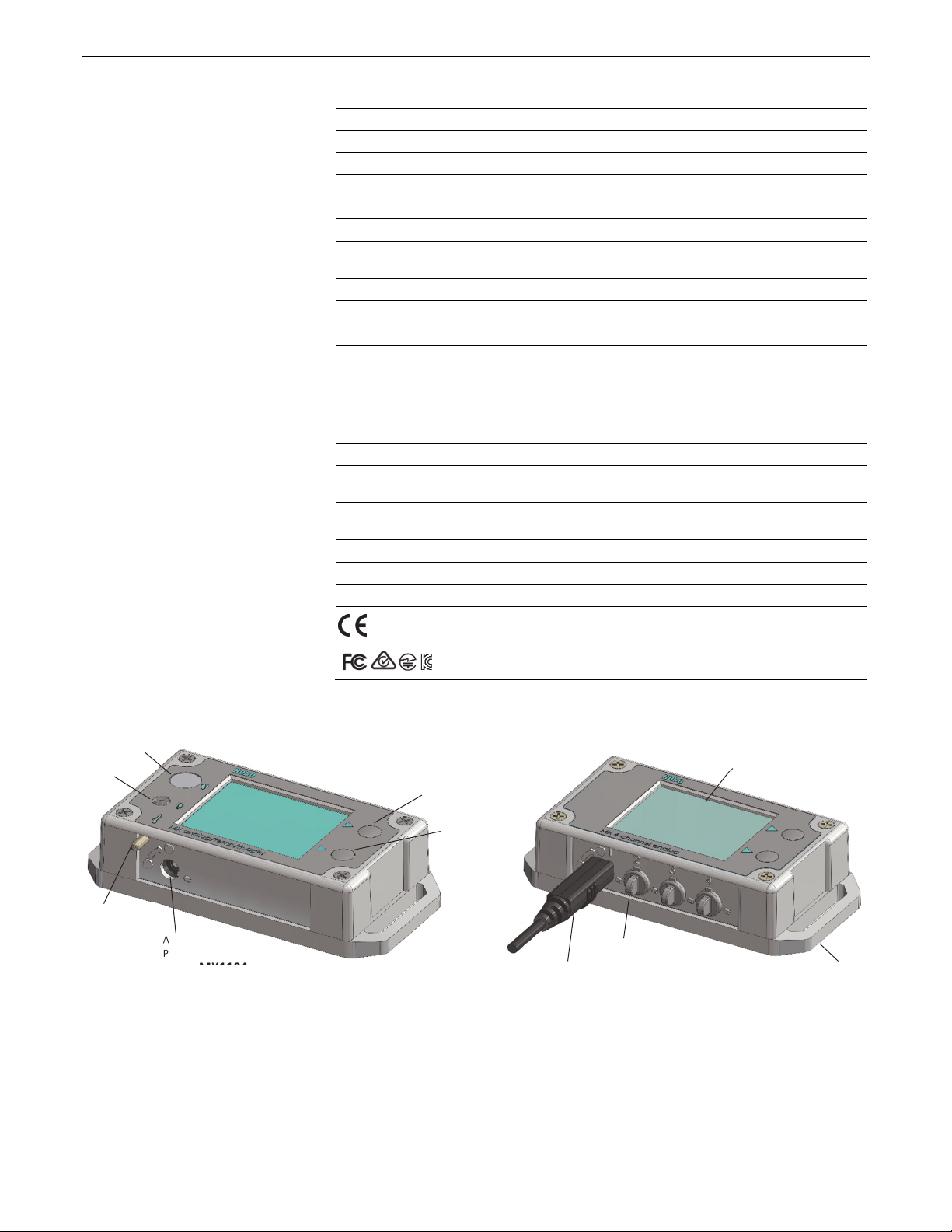
Logger Components and Operation
RH Sensor
Light Sensor
Temperature
Sensor (internal)
and Venting Pipe
RH Sensor: This sensor is located in the upper left corner and to
the left of the LCD screen in the MX1104 model.
Light Sensor: This sensor is located below the RH sensor and to
the left of the LCD screen in the MX1104 model.
Temperature Sensor: This sensor is located in the bottom left
corner and to the left of the LCD screen in the MX1104 model.
A small pipe protrudes from the bottom side of the logger case
to vent the temperature sensor.
Analog Sensor
Port
MX1104 Model
LCD Screen
Top Button
Bottom
Button
Self-Describing Sensor
Plug
MX1105 Model
Mounting
Loop
Analog Sensor Port: Use this 2.5 mm jack to connect a selfdescribing sensor or other analog sensor. The MX1104 model
has one port and the MX1105 model has four ports.
Top Button: Press this button for 3 seconds to start or stop
logging data, or to resume logging on the next even logging
interval. This requires configuring the logger in the app with a
push button start or stop, and with Allow Button Restart
selected (see Configuring the Logger).
Find Quality Products Online at: [email protected]
www.GlobalTestSupply.com
Page 3
HOBO MX Analog/Temp/RH/Light (MX1104) and MX 4-Channel Analog (MX1105) Manual
You can also press the top button for 1 second to wake up the
logger, bring the logger to the top of the list in the app, cycle
through each channel on the LCD, silence a beeping alarm (see
Setting up Alarms), and turn the LCD screen on if the option to
turn off the LCD has been enabled (see Configuring the Logger).
Bottom Button: When you are logging statistics, press this
button for 1 second to switch between the latest sensor
reading, statistics, and an alarm reading (if applicable) for the
channel currently displayed. If you are not logging statistics and
a sensor alarm trips, press this button for 1 second to view the
alarm reading for the channel currently displayed. You can also
press this button for 1 second to wake up the logger, silence a
beeping alarm, or turn the LCD screen on if the option to turn
off the LCD has been enabled. Press this button for 3 seconds to
clear a visual alarm if the logger was configured in the app to
maintain the visual alarm until the alarm button was pressed
(see Setting up Alarms). Press both the top and bottom buttons
simultaneously for 10 seconds to reset a logger password.
Self-Describing Sensor: This is a type of external sensor
available for MX1104 and MX1105 loggers. Turn the sensor
plug one-quarter clockwise when inserting it into an analog
sensor port to secure it in place. This sensor also features
automatic detection by the logger (see Working with Sensors).
Plug: Use this Santoprene® (TPE) plug to fill an empty analog
sensor port.
Mounting Loops: Use the two mounting loops (only one visible
in the diagrams) to mount the logger with tie wraps (see
Mounting the Logger).
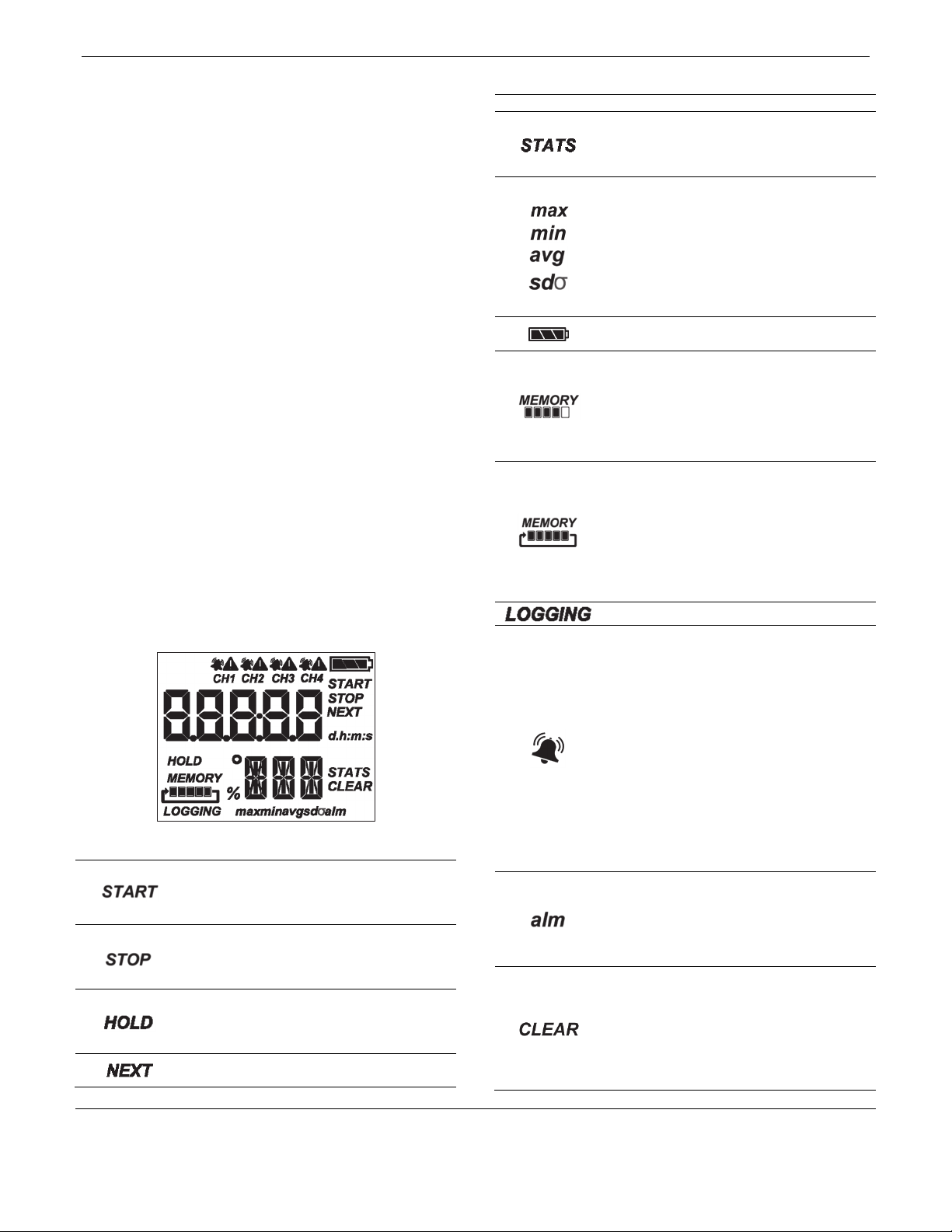
LCD Screen: This logger is equipped with an LCD screen that
displays details about the current status. This example shows all
symbols illuminated on the LCD screen followed by definitions
of each symbol.
LCD Symbol Description
The logger is waiting to be started or restarted.
Press and hold the top button for 3 seconds to
start the logger; the logger also displays HOLD
during this time.
The logger has been started with push button stop
enabled. Press and hold the top button for 3
seconds to stop the logger; the logger also displays
HOLD during this time.
The logger displays HOLD when you press the top
button for 3 seconds to start, stop, or restart the
logger, or while pressing the bottom button for 3
seconds to clear an alarm.
The logger displays NEXT when it is logging more
than one. Press the top button to cycle through
LCD Symbol Description
each channel to view sensor measurements.
The logger is logging statistics. Press the bottom
button to switch between the current sensor
readings, statistics, and any alarm readings for
each channel.
These symbols show the maximum, minimum,
average, and standard deviation values most
recently calculated by the logger (if the logging
mode is set to Fixed Logging Interval in the app
and you have selected each statistic; see Statistics
Logging). Press the bottom button to cycle
through the available statistics and then back to
the current sensor reading (or to the alarm value if
applicable).
The battery indicator shows the approximate
battery power remaining.
The logger is set to Stop When Memory Fills. The
memory bar indicates the approximate amount of
storage space remaining in the logger. When the
logger first starts logging data, all five segments
are empty. In this example, the logger memory is
almost full (only one segment in the memory bar is
empty).
The logger is set to Never Stop (Overwrites Old
Data). The logger continues recording data
indefinitely, with newest data overwriting the
oldest data until the battery voltage is depleted or
the logger is reconfigured. When the logger first
starts logging data, all five segments in the
memory bar are empty. In this example, the
memory is full (all five segments are filled) and
new data is now overwriting the oldest data.
The logger is currently logging.
The bell icon indicates a sensor alarm has tripped.
Press the top button to view the channel with the
alarm icon. Press the bottom button to view the
reading that tripped the alarm. The “alm” symbol
(described below) is displayed on the screen with
the reading (dashes are displayed if the alarm has
already cleared). The alarm symbol clears
depending on the setting for Show Visual Alarms
in the app. If the it is set to Logger Reconfigured
(clears when the logger is reconfigured), this
symbol remains until the next time new
configuration settings are loaded onto the logger
(see Configuring the Logger). Otherwise, it clears
when the sensor reading is back within the alarm
limits or when you press the bottom button for 3
seconds.
This is displayed with the reading that tripped the
alarm. While viewing the channel with the alarm,
press the bottom button to see the reading (you
may need to cycle through statistics readings first
if applicable). If the alarm cleared, dashes (- - - -)
appear instead of a reading.
A visual alarm is ready to be cleared. This appears
only if the setting for Show Visual Alarms in the
app is set to Alarm Button Pressed (maintain the
visual alarm until you press the alarm button).
While viewing the channel with the alarm on the
LCD, press the bottom button for 3 seconds to
clear the visual alarm. You can silence an audible
alarm by pressing the top or bottom button for 1
© 2019–2022 Onset Computer Corporation. All rights reserved. Onset, HOBO, HOBOconnect, and HOBOlink are
registered trademar ks of Onset Computer Corpor ation. App Store, iPhone, iPad, and iPadOS are service marks or
registered trademarks of Apple Inc. Android and Google Play are trademarks of Google LLC. Windows is a registered
trademark of Microsoft Corporation. Bluetooth and Bluetooth Smart are registered trademarks of Bluetooth SIG,
Inc. All other trademarks are the property of their respective companies.
Patent #: 8,860,569 23968-H
Find Quality Products Online at: [email protected]
www.GlobalTestSupply.com
Page 4
HOBO MX Analog/Temp/RH/Light (MX1104) and MX 4-Channel Analog (MX1105) Manual
LCD Symbol Description
second.
This indicates a problem with an external sensor.
See Working with External Sensors for more
details.
This is an example of a sensor reading, with the
latest reading displayed above the unit type for
that sensor. To switch between US and SI units,
change the units in the Settings area of the app
(reconfigure the logger to have your units changes
take effect). Note: If the sensor value exceeds five
digits, the scientific notation E3 is appended to the
value on the LCD to signify that the displayed
digits are multiplied by 1,000. For example, a value
of 100,000 is displayed as 100E3 on the LCD. This
only affects the LCD; logged data contains all
digits.
The logger has been configured to start logging on
a particular date/time. The display counts down in
days, hours, minutes, and seconds until logging
begins. In this example, 5 minutes and 38 seconds
remain until logging begins.
The configuration settings are being loaded onto
the logger from the app.
The logger was stopped by the app or because the
memory is full.
Notes:
• You can disable the LCD screen when logging. Deselect
“Show LCD” when setting up the logger as described in
the next section. When this option is disabled, you can
still temporarily view the LCD screen by pushing the top
or bottom button for 1 second. The LCD then remains on
for 10 minutes.
• The LCD screen refreshes at the same rate as the logging
interval.
• When the logger has stopped logging, the LCD screen
remains on with “STOP” displayed until you download
data from the logger to your mobile device (unless the
logger was configured with the “Show LCD” option
disabled). Once you have downloaded data from the
logger, the LCD turns off automatically after 1 hour. The
LCD turns back on the next time you press the top or
bottom button to wake up the logger.
• The LCD screen flashes “HELLO” when you page the
logger from the app (see Downloading the App and
Connecting to a Logger).
• The LCD screen flashes “BOOT” when a firmware upgrade
is underway.
• The LCD screen flashes “CHIRP OFF” when you clear an
audible alarm.
Button Functionality Quick Reference
Button
Top
button
Press for 1 second to:
• Cycle through each
channel to view the
Press and
hold for
3 seconds to:
Start, stop, or
resume
Press and
hold for 10
seconds to:
NA
Button Press for 1 second to:
latest sensor readings
• Wake up the logger
• Bring the logger to the
top of the list in the
app
• Silence a beeping
alarm
• Turn on LCD
Bottom
button
Both
buttons
• Cycle through any
statistics and alarm
readings for the
channel currently
displayed (if
applicable)
• Wake up the logger
• Silence a beeping
alarm
• Turn on LCD
NA NA Reset a
Press and
hold for
3 seconds to:
logging
(depending on
settings
chosen in the
app)
Clear an alarm
for the
channel
currently
displayed
(depending on
the settings
chosen in the
app)
Press and
hold for 10
seconds to:
NA
password
Light Measurement (MX1104)
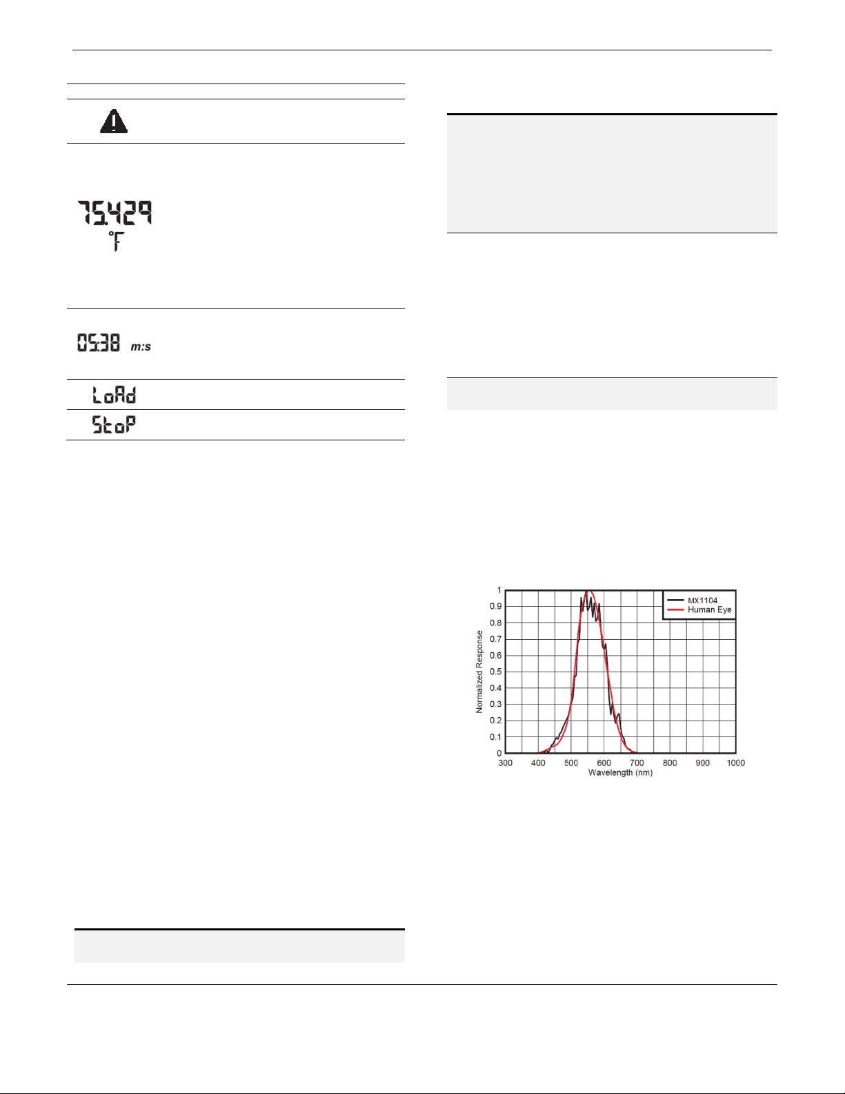
The MX1104 logger measures light intensity in units of
lumens/ft2 or lux. The light sensor in the MX1104 has a spectral
response that tightly matches the photopic response of the
human eye as illustrated in Plot A.
The light sensor has a range of 0 to 167,731 lux (15,582
2
lum/ft
). The resolution of the light measurement varies from 1
unit of lux or lum/ft2 in very dim light to 40 lux (4 lum/ft2) for a
full scale measurement.
Plot A
Light Measurement Accuracy
Although the MX1104 is factory calibrated to account for the
light attenuation of the plastic enclosure, you may notice a
difference in the MX1104 reading compared to a commercially
available lux meter. Ideally, a light meter’s response should be
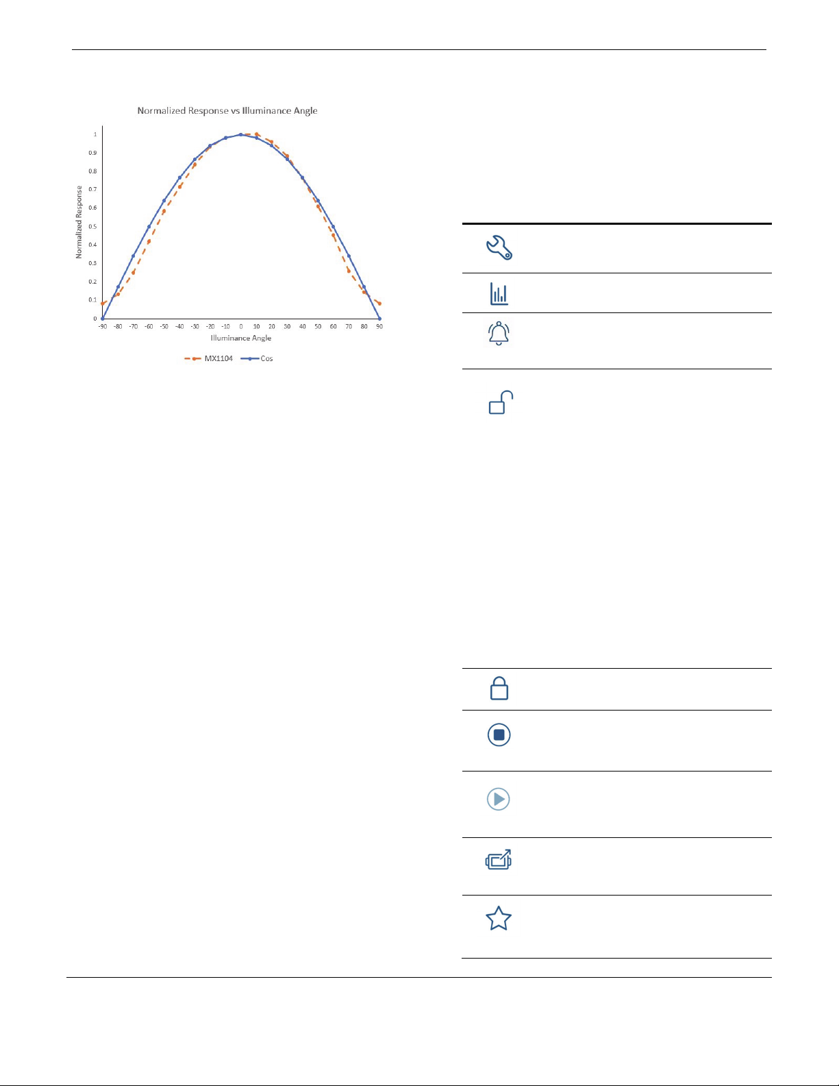
proportional to the cosine of the angle at which the light is
incident. The MX1104 does not collect light exactly according to
this rule. Plot B illustrates the difference between an ideal
cosine response and the approximate response of the MX1104.
© 2019–2022 Onset Computer Corporation. All rights reserved. Onset, HOBO, HOBOconnect, and HOBOlink are
registered trademar ks of Onset Computer Corpor ation. App Store, iPhone, iPad, and iPadOS are service marks or
registered trademarks of Apple Inc. Android and Google Play are trademarks of Google LLC. Windows is a registered
t
Find Quality Products Online at: [email protected]
www.GlobalTestSupply.com
trademark of Microsoft Corporation. Bluetooth and Bluetooth Smart are registered trademarks of Bluetooth SIG,
Inc. All other trademarks are the property of their respective companies.
Patent #: 8,860,569 23968-H
Page 5
HOBO MX Analog/Temp/RH/Light (MX1104) and MX 4-Channel Analog (MX1105) Manual
The MX1104 is calibrated to give best results for direct
illumination, but this is not always the case.
Plot B
The MX1104 is also calibrated to give best results in sunlight.
Because artificial indoor and outdoor lights have spectral
properties that differ from sunlight, the MX1104 may show an
error of greater than ±10% when compared to a commercially
available lux meter in these situations. Multiple MX1104
loggers, however, typically exhibit ±10% agreement with each
other in any type of light.
Downloading the App and
Connecting to a Logger
Install the app to connect to and work with the logger.
1. Download HOBOconnect to a phone or tablet from the App
Store® or Google Play™.
Download the app to a Windows computer from
www.onsetcomp.com/products/software/hoboconnect.
2. Open the app and enable Bluetooth in your device settings
if prompted.
3. Press either button on the logger to wake it up.
4. Tap Devices and then tap the logger tile in the app to
connect to the logger.
If the logger does not appear or if it is having trouble
connecting, follow these tips:
• If the logger is configured with Bluetooth Always On
disabled (see Configuring the Logger), make sure the
logger is “awake” by pressing the top or bottom button.
Press the top button again to bring the logger to the top
of the list if you are working with multiple loggers.
• Make sure the logger is within range of your mobile
device or computer. The range for successful wireless
communication is approximately 30.5 m (100 ft) with full
line-of-sight.
• If your device can connect to the logger intermittently or
loses its connection, move closer to the logger, within
sight if possible.
• Change the orientation of your device to ensure the
antenna is pointed toward the logger. Obstacles between
the antenna in the device and the logger may result in
intermittent connections.
• If the logger appears in the app, but you cannot connect
to it, close the app and then power down your device to
force the previous Bluetooth connection to close.
Once the logger is connected, you can:
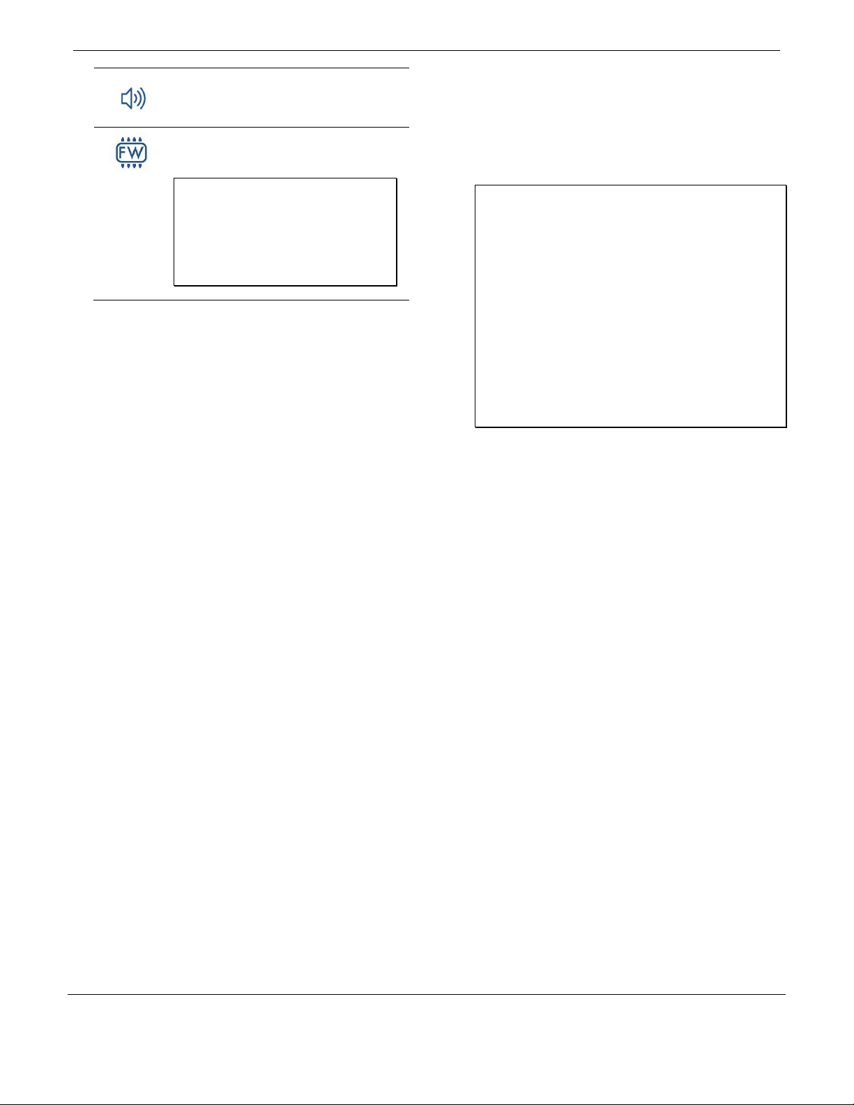
Tap this: To do this:
Specify logger settings and save them onto the
logger to start logging. See Configuring the
Logger.
Tap to view live data.
Stop a beeping alarm on the logger if audible
alarms are enabled as described in Setting up
Alarms.
Lock the logger. Set a password for the logger so
that it is not mistakenly stopped or reconfigured.
Tap the icon, enter a password, and then tap Set.
Once a password is entered on a phone or tablet,
that mobile device is the only one to
“remember” it. This means you can connect to
the logger without entering a password on that
mobile device, but you must enter a password on
all other mobile devices. For example, if you set
the password for the logger with your tablet and
then try to connect to the device later with your
phone, you must enter the password on the
phone but not with your tablet. Similarly, if
others attempt to connect to the logger with
different devices, they are also required to enter
the password.
To reset a password:
• Simultaneously press both the Start/Stop
button and the Alarm/Stats button for 3
seconds, or
• Tap Manage Password and then tap Reset.
Manage Password. Reset your existing password
or set a new password for the logger.
Stop logging data (this overrides any Stop
Logging settings described in Configuring the
Logger).
Start logging if the logger was configured to start
with a button push. See Configuring the Logger.
Download logger data. See Downloading Data
From the Logger.
Mark the logger as a favorite. You can then filter
the list of devices to show only loggers marked as
favorites.
© 2019–2022 Onset Computer Corporation. All rights reserved. Onset, HOBO, HOBOconnect, and HOBOlink are
registered trademar ks of Onset Computer Corpor ation. App Store, iPhone, iPad, and iPadOS are service marks or
registered trademarks of Apple Inc. Android and Google Play are trademarks of Google LLC. Windows is a registered
trademark of Microsoft Corporation. Bluetooth and Bluetooth Smart are registered trademarks of Bluetooth SIG,
Inc. All other trademarks are the property of their respective companies.
Patent #: 8,860,569 23968-H
Find Quality Products Online at: [email protected]
www.GlobalTestSupply.com
Page 6
HOBO MX Analog/Temp/RH/Light (MX1104) and MX 4-Channel Analog (MX1105) Manual
Make the logger beep one time to help you
locate it. “HELLO” also appears on the LCD when
the logger is paged.
Update the firmware on the logger. A logger
readout will be completed automatically at the
beginning of the firmware update process
Important: Before updating the firmware on
the logger, check the remaining battery level
and make sure it is no less than 30%. Make
sure you have the time to complete the
entire update process, which requires that
the logger remains connected to the device
during the upgrade.
Configuring the Logger
Use the app to set up the logger, including setting alarms,
selecting the options to start and stop logging, and choosing a
logging mode. These steps provide an overview of setting up
the logger. For complete details, see the HOBOconnect User
Guide.
1. In the app, tap Devices and then tap the logger tile to
connect to it.
2. Tap Configure & Start to configure the logger.
3. Tap Name and type a name for the logger (optional). If you
do not enter a name, the app uses logger serial number as
the name.
4. Tap Group to add the logger to a group (optional).
5. Tap Logging Interval and choose how frequently the logger
will record data unless operating in burst logging mode (see
Burst Logging).
6. Tap Start Logging and select when logging begins:
• On Save. Logging begins immediately after configuration
settings are saved.
• On Next Interval. Logging begins at the next even
interval as determined by the selected logging interval.
• On Button Push. Logging begins when you press either
the Start/Stop logging button on the logger for 3 seconds
or start logging with the app.
• On Date/Time. Logging begins at a date and time you
specify. Select the Date and Time.
7. Tap Stop Logging and specify when logging ends.
• Never Stop (Overwrites Old Data). The logger does
not stop at any predetermined time. The logger
continues recording data indefinitely, with newest data
overwriting the oldest.
• On Date/Time. The logger stops logging on a specific
date and time that you specify.
• After. Select this if you want to control how long the
logger should continue logging once it starts. Choose
the amount of time you want the logger to log data.
For example, select 30 days if you want the logger to
log data for 30 days after logging begins.
• Stop When Memory Fills. The logger continues
recording data until the memory is full.
8. Tap Pause Options, then select Pause On Button Push to
specify that you can pause the logger by pressing its
Start/Stop button for 3 seconds. Select Allow Button
Resume to specify that you can press the Start/Stop button
on the logger to resume logging.
Important: When you select Allow Button Resume and
you use the Start/Stop button on the logger to stop and
restart logging, logging restarts on the next even logging
interval, not at the time you pushed the button. For
example, a logger started logging at 7:00 AM with a
logging interval set to 1 hour. If you press the Start/Stop
button to stop the logger at 8:45 AM and then press the
button again at 10:15 AM, logging will not begin
immediately at 10:15 AM. Instead, logging will begin
again at 11:00 AM, which is the next even interval time
based on your 1-hour logging interval. Depending on the
logging interval, the gap between the time you press the
button to resume logging and the time actual logging
begins could be significant. The faster the logging
interval, the less time elapses before logging resumes.
9. Tap Logging Mode. Select either fixed or burst logging. With
fixed logging, the logger records data for all enabled sensors
and/or selected statistics at the logging interval selected
(see Statistics Logging for details on choosing statistics
options). In burst mode, logging occurs at a different
interval when a specified condition is met. See Burst
Logging for more information.
10. Enable or disable Show LCD, which controls whether the
LCD on the logger remains illuminated while the logger is
logging. If you disable Show LCD, the LCD on the logger does
not show the current reading, status, or other information
while the logger is logging. You can temporarily turn the
LCD screen on by pressing the Start/Stop button on the
logger for 1 second. In addition, you can always view the
status of any in-range logger on your mobile device
regardless of the logger’s LCD setting (may require a logger
password as applicable).
11. Enable or disable Bluetooth Always On. If Bluetooth Always
On is enabled, the logger advertises or regularly sends out a
Bluetooth signal for the phone, tablet, or computer to find
via the app while it is logging, which uses battery power.
When Bluetooth Always On is disabled, the logger only
advertises during logging when you press either button on
the logger to wake it up, thereby preserving as much
battery power as possible.
12. Select whether to upload data to HOBOlink® via the
gateway or the app (optional and requires an active
HOBOlink account).
13. Make sure all channels you want to log are enabled and
then do the following:
• For self-describing sensors, the sensor type is
automatically detected. Tap the sensor if you want to
enter a label, set up alarms, or add scaling.
© 2019–2022 Onset Computer Corporation. All rights reserved. Onset, HOBO, HOBOconnect, and HOBOlink are
registered trademar ks of Onset Computer Corpor ation. App Store, iPhone, iPad, and iPadOS are service marks or
registered trademarks of Apple Inc. Android and Google Play are trademarks of Google LLC. Windows is a registered
Find Quality Products Online at: [email protected]
www.GlobalTestSupply.com
trademark of Microsoft Corporation. Bluetooth and Bluetooth Smart are registered trademarks of Bluetooth SIG,
Inc. All other trademarks are the property of their respective companies.
Patent #: 8,860,569 23968-H
Page 7
HOBO MX Analog/Temp/RH/Light (MX1104) and MX 4-Channel Analog (MX1105) Manual
• For other external sensors, the sensor type is not
automatically detected. Enable the channel (if necessary)
and then tap it to enter a label (optional). Select the type
of sensor or cable from the list. Set up alarms and add
scaling if needed and then tap Save.
• See Working with External Sensors and Setting up Alarms
for additional details.
14. Tap Start to save the configuration settings.
Logging begins based on the settings you selected. Deploy the
logger using the mounting materials (see Mounting the Logger).
After logging begins, you can download data from the logger at
any time (see Downloading Data From the Logger for details).
Note: If an “Error Configuring Logger” message appears in the
app, an error occurred while loading the configure settings onto
the logger. Try reconfiguring the logger.
Working with External Sensors
The MX1104 has one analog sensor port and the MX1105 has
four analog sensor ports that can accept self-describing and
other external sensors. Refer to www.onsetcomp.com for a
current list of supported sensors.
To connect an external sensor:
1. Make sure the logger is stopped.
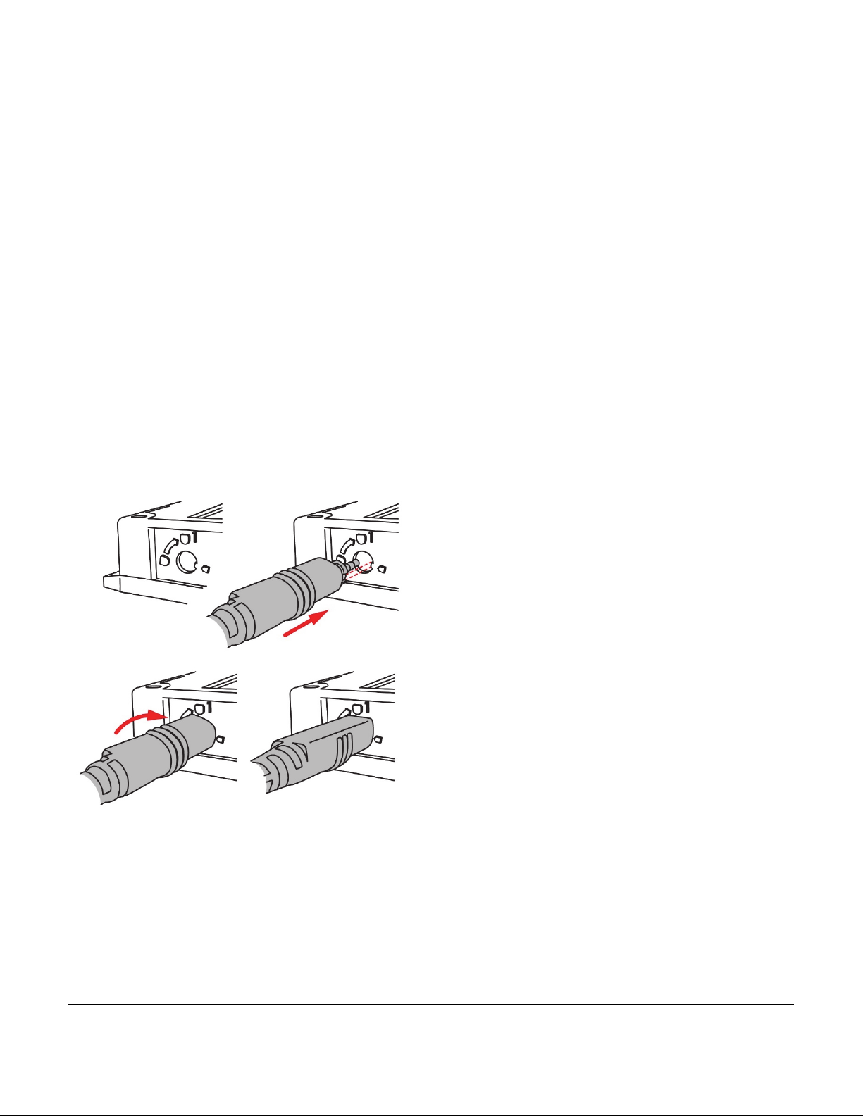
2. For self-describing sensors, insert the plug into an analog
sensor port as shown.
a.
Using the diagram on the
logger housing shown above as
reference, insert the plug into
the analog sensor port.
c.
Turn the plug onequarter clockwise.
3. For other external sensors, insert the sensor into an analog
sensor port and make sure it is firmly seated.
4. If you need to connect a sensor to the sensor cable,
complete any wiring before logging begins. Refer to the
sensor or cable manual for more information on connecting
the sensor and wiring, if applicable.
5. Tap Devices. Press either button on the logger to wake it up
(if necessary).
6. Tap the logger tile in the app to connect to the logger and
tap Configure & Start.
b.
d.
The flat part of the plug will be
facing up when properly installed.
7. Make sure all external sensor channels are enabled.
8. For self-describing sensors, the sensor type is automatically
detected. Tap the Sensor/Channel Name in the app to enter
a label (optional). To set up scaling (if it is present), tap
Scaling and then enter the Series Name, Unit, and values for
High and Low and then tap Save. See Setting up Alarms for
details on adding alarms.
For other external sensors, the sensor type is not
automatically detected. Tap the sensor and enable the
channel (if necessary). Enter a label (optional). Select the
type of sensor or cable from the list. To set up scaling (if it’s
present), tap Scaling and then enter the Series Name, Unit,
and values for High and Low and then tap Save. See Setting
up Alarms for details on adding alarms.
Notes:
• For MX1104 loggers, an external sensor is channel 1. For
MX1105 loggers, the sensor channel number is listed
above the analog sensor port where the external sensor
is connected.
• The configuration screen in the app automatically
updates to show when a sensor is disconnected or
connected.
• Make sure you select the correct sensor type in the app if
you are not using self-describing sensors. If you select the
wrong type, incorrect data is logged. The app
automatically detects the sensor type only for selfdescribing sensors.
• If you disconnect a sensor or if it is not fully inserted into
the analog sensor port while the logger is logging, a
warning icon appears on the LCD and the logger beeps
once. Use the top button on the logger to view the
channel with the warning, which also displays dashes
instead of a valid current reading. Erroneous readings are
displayed in the app and logged depending on the
logging interval while the sensor is disconnected (e.g., if a
sensor is disconnected for 5 minutes and the logging
interval is set to 1 minute, there are 5 erroneous data
points while the sensor was disconnected). When the
sensor is reconnected, the warning icon clears, the
correct value replaces the dashes for the channel on the
LCD, and the correct readings are logged.
• Do not swap out sensors or move sensors to empty ports
while the logger is logging. Stop the logger before making
any physical changes to the sensors.
• If a warning icon appears for a self-describing sensor and
you have checked that the correct sensor is properly
installed, the sensor might be faulty. Contact Onset
Technical Support.
• The 4-20mA input cable (SD-MA-420 or CABLE-4-20mA)
measures current from 0 to 20.1 mA. Do not expose it to
current above 20 mA or to negative current. Do not cut
off the end of the gray cable where it connects to the
blue and yellow wires as it contains the precision resistor
required for current measurement.
• If you are using the SD-VOLT-2.5 or CABLE-2.5-STEREO
voltage input cable, the input line must not be exposed
© 2019–2022 Onset Computer Corporation. All rights reserved. Onset, HOBO, HOBOconnect, and HOBOlink are
registered trademar ks of Onset Computer Corpor ation. App Store, iPhone, iPad, and iPadOS are service marks or
registered trademarks of Apple Inc. Android and Google Play are trademarks of Google LLC. Windows is a registered
trademark of Microsoft Corporation. Bluetooth and Bluetooth Smart are registered trademarks of Bluetooth SIG,
Inc. All other trademarks are the property of their respective companies.
Patent #: 8,860,569 23968-H
Find Quality Products Online at: [email protected]
www.GlobalTestSupply.com
Page 8
HOBO MX Analog/Temp/RH/Light (MX1104) and MX 4-Channel Analog (MX1105) Manual
to signals below 0 V or above 2.5 V. The voltage input
cable connections are as follows:
Wire Connection
Red Switched 2.5 V output
White Voltage input
Black Ground
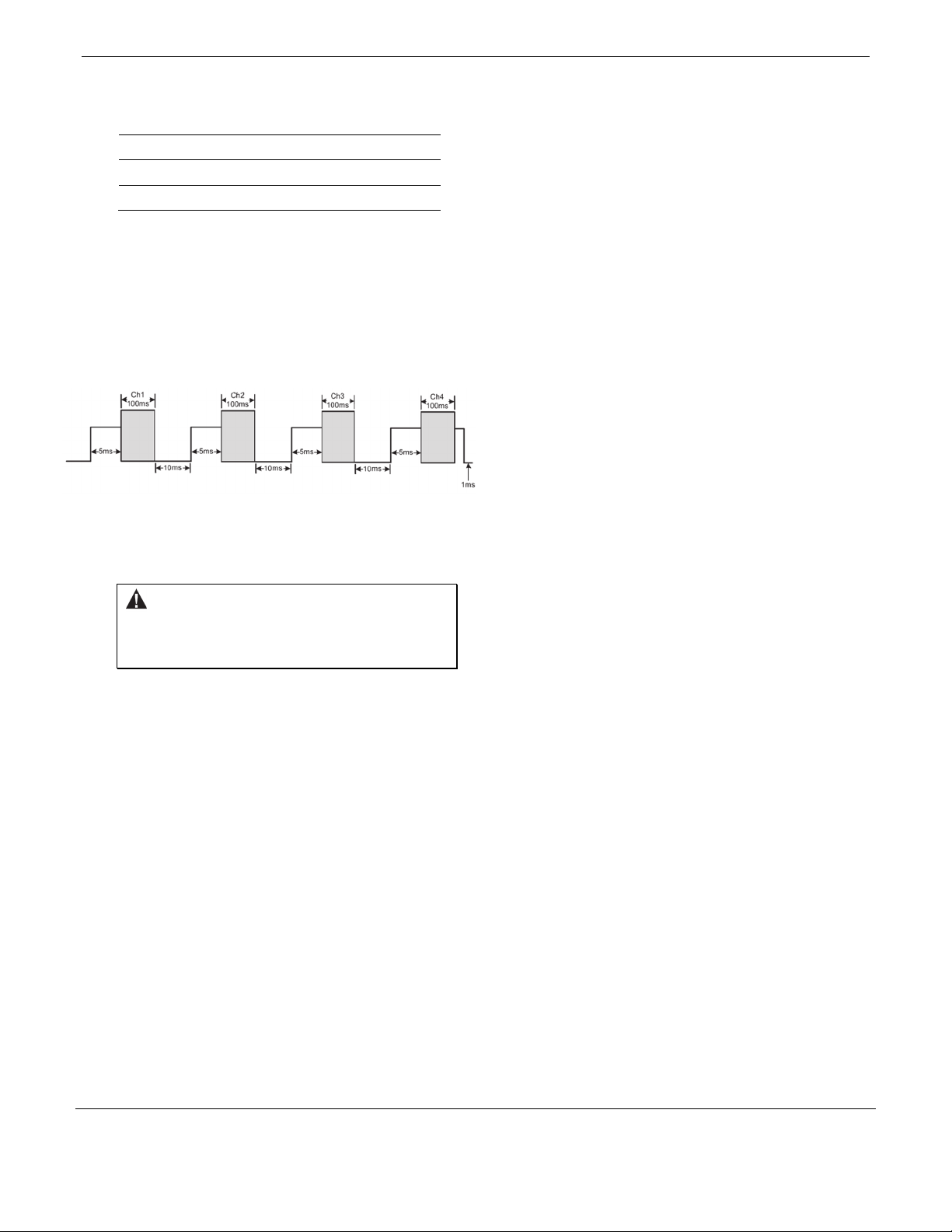
• The external input channels have a switched 2.5 V
output. This signal can be used to power a sensor directly
or to trigger an external circuit. External sensors should
draw no more than 4 mA total when powered.
The switched 2.5 V output turns on about 5 ms before
the external channels are measured as shown in the
following diagram for an MX1105 logger. The shaded
area shows the 100 ms period for each enabled channel
during which the logger samples the input signals.
When using multiple voltage and/or current inputs, the
(-) from the current source(s) and the 0 V line from the
voltage source(s) are tied together at the logger. If these
lines are at different voltage potentials, this may cause
inaccurate readings or even damage your logger.
WARNING: Analog channel input cannot exceed 2.5
V DC. For sensor outputs up to 24 V DC, use the
appropriate voltage adapter cable (SD-VOLT-xx or
CABLE-ADAPX).
Setting up Alarms
You can set an alarm to trip on the logger when a sensor
reading rises above or falls below a specified value. Alarms alert
you to problems so you can take corrective action. To set an
alarm:
1. Tap Devices.
2. Tap the logger tile in the app to connect to the logger and
tap Configure & Start.
3. Tap a Sensor/Channel.
4. Tap Enable Logging, if necessary.
5. Tap Alarms to open that area of the screen.
6. Select Low if you want an alarm to trip when the sensor
reading falls below the low alarm value. Enter a value to set
the low alarm value.
7. Select High if you want an alarm to trip when the sensor
reading rises above the high alarm value. Enter a value to
set the high alarm value.
8. For the Duration, select how much time should elapse
before the alarm trips and select one of the following:
• Cumulative Samples. The alarm trips once the sensor
reading is out of the acceptable range for the selected
duration any time during logging. For example, if the high
alarm is set to 85°F and the duration is set to 30 minutes,
the alarm trips once the sensor readings have been
above 85°F for a total of 30 minutes since the logger was
configured.
• Consecutive Samples. The alarm trips once the sensor
reading is out of the acceptable range continuously for
the selected duration. For example, the high alarm is set
to 85°F and the duration is set to 30 minutes, the alarm
trips only if all sensor readings are 85°F or above for a
continuous 30-minute period.
9. Repeat steps 2–8 for the other sensor.
10. In the Alarm Settings area, enable Audible Alarm if you
want the logger to beep every 30 seconds when the sensor
alarm trips. The beeping continues until you clear the alarm
in the app, press either button on the top of the logger, or 7
days have passed. Battery life is slightly reduced when this
setting is enabled. It is recommended that you enable this
feature only if you have regular access to the logger so that
you can easily turn off the beeping.
11. For Show Visual Alarms Until, select one of the following
options to determine how long the alarm icon remains
illuminated on the logger LCD screen after an alarm trips:
• Logger Reconfigured. The alarm icon remains visible on
the LCD until the next time the logger is reconfigured.
• Sensor in Limits. The alarm icon remains visible on the
LCD until the sensor reading returns to the normal range
between any configured high and low alarm limits.
• Alarm Button Pressed. The alarm icon remains visible
until you press the Alarm/Stats button on the logger.
Notes:
• The alarm icon is illuminated on the logger LCD when the
alarm trips. You can also press the Alarms/Stats button
on the logger to view the farthest out-of-range value
during the deployment. Dashes appear instead of a value
once the alarm is cleared on the channel. The logger
checks alarm limits at the same rate as the logging
interval.
• The actual values for the high and low alarm limits are set
to the closest value supported by the logger. In addition,
alarms can trip or clear when the reading is within the
resolution specifications. This means the value that
triggers the alarm may differ slightly from the value
entered.
• When you download data from the logger, alarm events
can be displayed
on the plot or in the data file. See
Logger Events.
• Once cleared, an audible alarm will start beeping again if
the sensor values go out of the normal range. Even if you
clear an audible alarm, a visual alarm may remain on the
logger LCD and in the app depending on the settings
selected for Show Visual Alarms Until or because the
alarm condition may still be in effect. In addition, an
© 2019–2022 Onset Computer Corporation. All rights reserved. Onset, HOBO, HOBOconnect, and HOBOlink are
registered trademar ks of Onset Computer Corpor ation. App Store, iPhone, iPad, and iPadOS are service marks or
registered trademarks of Apple Inc. Android and Google Play are trademarks of Google LLC. Windows is a registered
trademark of Microsoft Corporation. Bluetooth and Bluetooth Smart are registered trademarks of Bluetooth SIG,
Inc. All other trademarks are the property of their respective companies.
Find Quality Products Online at: [email protected]
www.GlobalTestSupply.com
Patent #: 8,860,569 23968-H
Page 9
HOBO MX Analog/Temp/RH/Light (MX1104) and MX 4-Channel Analog (MX1105) Manual
audible alarm continues beeping when the sensor values
have returned to the normal range until it is cleared.
• Although an audible alarm and a visual alarm can occur
at the same time when a sensor alarm is tripped, you
clear them different ways. The audible alarm can be
cleared as described in step 10. Meanwhile, a visual
alarm is cleared as determined by the setting selected for
Show Visual Alarms Until configuration setting. This
means you could clear a beeping audible alarm and the
visual alarm remains on the LCD and in the app until the
logger is reconfigured, the sensor is in limits, or the
bottom button on the logger is pressed--whichever
setting you selected.
• If the logger is configured to stop logging with a button
push, any tripped alarms are cleared automatically when
logging is stopped and no Alarm Cleared event is logged
in the data file. This ensures that the logger starts
checking for alarm conditions when logging resumes (if
the logger was configured with Allow Button Resume
selected).
Burst Logging
Burst logging is a logging mode that allows you to set up more
frequent logging when a specified condition is met. For
example, a logger is recording data at a 5-minute logging
interval and burst logging is configured to log every 30 seconds
when the temperature rises above 85°F (the high limit) or falls
below 32°F (the low limit). This means the logger records data
every 5 minutes as long as the temperature remains between
85°F and 32°F. Once the temperature rises above 85°F, the
logger switches to the faster logging rate and records data
every 30 seconds until the temperature falls back to 85°F. At
that time, logging then resumes every 5 minutes at the fixed
logging interval. Similarly, if the temperature falls below 32°F,
then the logger switches to burst logging mode again and
record data every 30 seconds. Once the temperature rises back
to 32°F, the logger then returns to fixed mode, logging every 5
minutes. Note: Sensor alarms, statistics, and the Stop Logging
option Never Stop (Overwrites Old Data) are not available in
burst logging mode.
To set up burst logging:
1. Tap Devices. Press the Start/Stop button on the logger to
wake it up, if necessary.
2. Tap the logger tile in the app to connect to the logger and
tap Configure & Start.
3. Tap Logging Mode and then tap Burst Logging.
4. Set the burst logging interval, which must be faster than the
logging interval. Keep in mind that the faster the burst
logging rate, the greater the impact on battery life and the
shorter the logging duration. Because measurements are
being taken at the burst logging interval throughout the
deployment, the battery usage is similar to what it would be
if you had selected this rate for the normal logging interval.
5. Select Low and/or High and type a value to set the low
and/or high values.
6. Repeat step 5 for other sensors as necessary.
Notes:
• The logger checks burst limits at the same rate as the
logging interval. When the logger enters burst logging
mode, the LCD updates at the same rate as the new burst
logging interval.
• If high and/or low limits are configured for more than
one sensor, burst logging begin when any high or low
condition goes out of range. Burst logging does not end
until all conditions on all sensors are back within normal
range.
• The actual values for the burst logging limits are set to
the closest value supported by the logger.
• Burst logging mode can begin or end when the sensor
reading is within the resolution specifications. This means
the value that triggers burst logging may differ slightly
from the value entered.
• Once the high or low condition clears, the logging
interval time is calculated using the last recorded data
point in burst logging mode, not the last data point
recorded in fixed mode. For example, let’s assume the
logger has a 10-minute logging interval and logged a data
point at 9:05. The high limit is surpassed and burst
logging begins at 9:06. Burst logging then continues until
9:12 when the sensor reading falls back below the high
limit. Now back in fixed mode, the next logging interval is
10 minutes from the last burst logging point, or 9:22 in
this case. If burst logging had not occurred, the next data
point would have been at 9:15.
• A New Interval event is created each time the logger
enters or exits burst logging mode. See Logger Events for
details on plotting and viewing the event. In addition, if
the logger is stopped with a button push while in burst
logging mode, a New Interval event is automatically
logged and the burst condition is cleared, even if the
actual high or low condition has not cleared. The logger
checks the high and low conditions when logging
resumes (if the logger was configured with Allow Button
Resume selected).
Statistics Logging
During fixed logging, the logger records data for enabled
sensors and/or selected statistics at the logging interval
selected. Statistics are calculated at a sampling rate you specify
with the results for the sampling period recorded at each
logging interval. You can log the following statistics for each
sensor:
• The maximum, or highest, sampled value
• The minimum, or lowest, sampled value
• An average of all sampled values
• The standard deviation from the average for all sampled
values
For example, a logger is configured with both the temperature
and RH sensors enabled, and the logging interval set to 5
minutes. The logger is set to Fixed Logging Mode and all four
statistics are enabled and with a statistics sampling interval of
© 2019–2022 Onset Computer Corporation. All rights reserved. Onset, HOBO, HOBOconnect, and HOBOlink are
registered trademar ks of Onset Computer Corpor ation. App Store, iPhone, iPad, and iPadOS are service marks or
registered trademarks of Apple Inc. Android and Google Play are trademarks of Google LLC. Windows is a registered
Find Quality Products Online at: [email protected]
www.GlobalTestSupply.com
trademark of Microsoft Corporation. Bluetooth and Bluetooth Smart are registered trademarks of Bluetooth SIG,
Inc. All other trademarks are the property of their respective companies.
Patent #: 8,860,569 23968-H
Page 10
HOBO MX Analog/Temp/RH/Light (MX1104) and MX 4-Channel Analog (MX1105) Manual
30 seconds. Once logging begins, the logger measures and
records the actual temperature and RH sensor values every 5
minutes. In addition, the logger takes a temperature and RH
sample every 30 seconds and temporarily stores them in
memory. The logger then calculates the maximum, minimum,
average, and standard deviation using the samples gathered
over the previous 5-minute period and logs the resulting values.
When downloading data from the logger, this results in 10 data
series (not including any derived series, such as dew point): two
sensor series (with temperature and RH data logged every 5
minutes) plus eight maximum, minimum, average, and standard
deviation series (four for temperature and four for RH with
values calculated and logged every 5 minutes based on the 30second sampling).
To log statistics:
1. Tap Devices. Press either button on the logger to wake it
up, if necessary.
2. Tap the logger tile in the app to connect to the logger and
tap Configure & Start.
3. Tap Logging Mode and select Fixed Logging Mode.
4. Tap to turn on Statistics.
Note: Fixed Logging Mode records sensor measurements
taken at each logging interval. The selections you make in
the Statistics section add measurements to the recorded
data.
5. Select the statistics you want the logger to record at each
logging interval: Maximum, Minimum, Average, and
Standard Deviation (average is automatically enabled when
selecting Standard Deviation). Statistics are logged for all
enabled sensors. In addition, the more statistics you record,
the shorter the logger duration and the more memory is
required.
6. Enter a value in Statistics Sampling Interval to use for
calculating statistics. The rate must be less than, and a
factor of, the logging interval. For example, if the logging
interval is 1 minute and you select 5 seconds for the
sampling rate, the logger takes 12 sample readings between
each logging interval (one sample every 5 seconds for a
minute) and use the 12 samples to record the resulting
statistics at each 1-minute logging interval. Note that the
faster the sampling rate, the greater the impact on battery
life. Because measurements are being taken at the statistics
sampling interval throughout the deployment, the battery
usage is similar to what it would be if you had selected this
rate for the normal logging interval.
Once logging begins, click the bottom button on the logger to
cycle through the current maximum, minimum, average, and
standard deviation data for the current channel displayed on
the LCD screen. Note that the logger always displays the
current sensor readings in the app even if they are not being
logged. You can plot the statistics series once you read out the
logger.
Setting a Password
You can create an encrypted password for the logger that is
required if another device attempts to connect to it. This is
recommended to ensure that a deployed logger is not
mistakenly stopped or purposely altered by others. This
password uses a proprietary encryption algorithm that changes
with every connection.
To set a password:
1. Tap Devices. Press the Start/Stop button on the logger to
wake it up, if necessary. Tap the logger tile in the app to
connect to it.
2. Tap Lock Logger.
3. Type a password and then tap Set.
Only the device used to set the password can then connect to
the logger without entering a password; all other devices are
required to enter the password. For example, if you set the
password for the logger with your tablet and then try to
connect to the logger later with your phone, you must enter
the password on the phone but not with your tablet. Similarly,
if others attempt to connect to the logger with different
devices, they are also required to enter the password. To reset
a password, press both buttons on the logger for 10 seconds or
connect to the logger and tap Manage Password and tap Reset.
Downloading Data From the Logger
To download data from the logger:
1. Tap Devices. Press either button on the logger to wake it
up, if necessary. Tap the logger tile in the app to connect to
the logger.
2. Tap Download Data. The logger downloads data to the
phone, tablet, or computer.
3. Once the download is complete, tap Done to return to the
previous page or tap Export and Share to save the file in the
specified format.
4. When the export file has successfully been created, tap
Done to return to the previous page or tap Share to use
your device’s usual modes of sharing.
You can also upload data automatically to HOBOlink, Onset’s
web-based software, using the app or the MX gateway. For
details, see the HOBOconnect User Guide and see the HOBOlink
help for details on working with data in HOBOlink.
Logger Events
The logger records the following internal events to track logger
operation and status. You can view events in exported files or
plot events in the app.
To plot events, tap Data and select a file to open.
Tap (if applicable) and then tap . Select the events you
want to plot and tap OK.
Internal Event Name Definition
Host Connected The logger was connected to the mobile
device.
© 2019–2022 Onset Computer Corporation. All rights reserved. Onset, HOBO, HOBOconnect, and HOBOlink are
registered trademar ks of Onset Computer Corpor ation. App Store, iPhone, iPad, and iPadOS are service marks or
registered trademarks of Apple Inc. Android and Google Play are trademarks of Google LLC. Windows is a registered
trademark of Microsoft Corporation. Bluetooth and Bluetooth Smart are registered trademarks of Bluetooth SIG,
Inc. All other trademarks are the property of their respective companies.
Find Quality Products Online at: [email protected]
www.GlobalTestSupply.com
Patent #: 8,860,569 23968-H
Page 11
HOBO MX Analog/Temp/RH/Light (MX1104) and MX 4-Channel Analog (MX1105) Manual
Internal Event Name Definition
Started
Stopped The logger received a command to stop
Chan <#> Alarm
Tripped
Chan <#> Alarm
Cleared
New Interval The logger has entered or exited burst
Safe Shutdown
The top button on the logger was pressed to
begin or resume logging.
recording data (from the app or by pushing
the top button on the logger).
A sensor alarm has tripped; <#> is the sensor
number, 1 through 4.
A sensor alarm has cleared; <#> is the sensor
number, 1 through 4. This event also
contains the value that was furthest out of
range for the sensor before the alarm
cleared, which is only available in a shared or
exported file.
logging mode.
The battery level dropped below 1.6 V; the
logger performs a safe shutdown.
Mounting the Logger
Use the four magnets on the back of the logger to mount it to a
magnetic surface or insert the tie wraps through the mounting
loops to attach it to other surfaces. Insert a Santoprene plug
into any empty analog sensor ports if necessary.
Protecting the Logger
The logger is designed for indoor use and can be permanently
damaged by corrosion if it gets wet. Protect it from
condensation.
Note: Static electricity may cause the logger to stop logging.
The logger has been tested to 8 KV, but avoid electrostatic
discharge by grounding yourself to protect the logger. For more
information, search for “static discharge” on onsetcomp.com.
Battery Information
The logger requires two user-replaceable AAA 1.5 V alkaline or
optional lithium batteries for operation at the extreme ends of
the logger operating range. Battery life is 1 year, typical with a
logging interval of 1 minute, but may be extended to 2 years
when the logger is configured with Bluetooth Always On
disabled. Expected battery life varies based on the ambient
temperature where the logger is deployed, the logging or
sampling interval, frequency of offloading and connection to
the mobile device, number of channels that are active, audible
alarms duration, use of burst mode or statistics logging, and
battery performance. Deployments in extremely cold or hot
temperatures, a logging interval faster than 1 minute, or a
sampling interval faster than 15 seconds can impact battery
life. Estimates are not guaranteed due to uncertainties in initial
battery conditions and operating environment.
To replace the batteries:
1. Use a Phillips-head screwdriver to unscrew the four screws
on the front of the logger.
2. Carefully separate the top and bottom of the logger
enclosure.
3. Remove any old batteries and insert new batteries
observing polarity.
4. Make sure the rubber seal on the bottom part of the logger
enclosure is clean and free of any debris.
5. Carefully reassemble the logger enclosure and screw in the
four screws.
WARNING: Do not cut open, incinerate, heat above 85°C
(185°F), or recharge lithium batteries. The batteries may
explode if the logger is exposed to extreme heat or conditions
that could damage or destroy the battery cases. Do not dispose
of the logger or batteries in fire. Do not expose the contents of
the batteries to water. Dispose of the batteries according to
local regulations for lithium batteries.
© 2019–2022 Onset Computer Corporation. All rights reserved. Onset, HOBO, HOBOconnect, and HOBOlink are
registered trademar ks of Onset Computer Corpor ation. App Store, iPhone, iPad, and iPadOS are service marks or
registered trademarks of Apple Inc. Android and Google Play are trademarks of Google LLC. Windows is a registered
trademark of Microsoft Corporation. Bluetooth and Bluetooth Smart are registered trademarks of Bluetooth SIG,
Inc. All other trademarks are the property of their respective companies.
Patent #: 8,860,569 23968-H
Find Quality Products Online at: [email protected]
www.GlobalTestSupply.com
Page 12
HOBO MX Analog/Temp/RH/Light (MX1104) and MX 4-Channel Analog (MX1105) Manual
Federal Communication Commission Interference Statement
This equipment has been tested and found to comply with the limits for a Class B digital device, pursuant to Part 15 of the FCC Rules. These limits are designed to provide
reasonable protection against harmful interference in a residential installation. This equipment generates uses and can radiate radio frequency energy and, if not installed and
used in accordance with the instructions, may cause harmful interference to radio communications. However, there is no guarantee that interference will not occur in a
particular installation. If this equipment does cause harmful interference to radio or television reception, which can be determined by turning the equipment off and on, the user
is encouraged to try to correct the interference by one of the following measures:
• Reorient or relocate the receiving antenna
• Increase the separation between the equipment and receiver
• Connect the equipment into an outlet on a circuit different from that to which the receiver is connected
• Consult the dealer or an experienced radio/TV technician for help
This device complies with Part 15 of the FCC Rules. Operation is subject to the following two conditions: (1) This device may not cause harmful interference, and (2) this device
must accept any interference received, including interference that may cause undesired operation.
FCC Caution: Any changes or modifications not expressly approved by the party responsible for compliance could void the user's authority to operate this equipment.
Industry Canada Statements
This device complies with Industry Canada license-exempt RSS standard(s). Operation is subject to the following two conditions: (1) this device may not cause interference, and
(2) this device must accept any interference, including interference that may cause undesired operation of the device.
Avis de conformité pour l’Industrie Canada
Le présent appareil est conforme aux CNR d'Industrie Canada applicables aux appareils radio exempts de licence. L'exploitation est autorisée aux deux conditions suivantes : (1)
l'appareil ne doit pas produire de brouillage, et (2) l'appareil doit accepter tout brouillage radioélectrique subi, même si le brouillage est susceptible d'en compromettre le
fonctionnement.
To comply with FCC and Industry Canada RF radiation exposure limits for general population, the logger must be installed to provide a separation distance of at least 20cm from
all persons and must not be co-located or operating in conjunction with any other antenna or transmitter.
KC Statement
해당 무선설비는 전파혼신 가능성이 있으므로 인명안전과 관련된 서비스는 할 수 없음
Translation:
The service related to human safety is not allowed because this device may have the possibility of the radio interference.
© 2019–2022 Onset Computer Corporation. All rights reserved. Onset, HOBO, HOBOconnect, and HOBOlink are
registered trademar ks of Onset Computer Corpor ation. App Store, iPhone, iPad, and iPadOS are service marks or
registered trademarks of Apple Inc. Android and Google Play are trademarks of Google LLC. Windows is a registered
trademark of Microsoft Corporation. Bluetooth and Bluetooth Smart are registered trademarks of Bluetooth SIG,
Inc. All other trademarks are the property of their respective companies.
Patent #: 8,860,569 23968-H
Find Quality Products Online at: [email protected]
www.GlobalTestSupply.com
 Loading...