

Page 1
Smart Sensor Adapter Case (S-ADAPT-6)
Items included:
• One case
• One plastic case cover
• Four mounting feet
• Four small Phillips-head screws (for attaching mounting feet
to case)
• Four long Phillips-head screws (for attaching case to wall)
• Six cable guide plugs
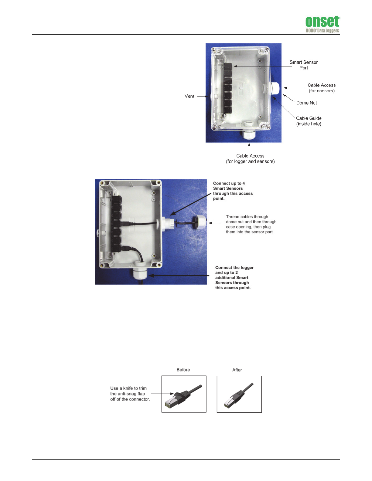
The smart sensor adapter case allows you to connect up to six
smart sensors in a moisture-resistant enclosure to a single smart
sensor extension cable back to a HOBO® station. The case is
tested to NEMA 4X (IP65) Standards for protection from
corrosion, wind-blown dust and rain, splashing water, and hosedirected water.
Assembly Instructions
This section explains how to connect smart sensors in the case, including the tools required for assembly.
To complete the assembly, you will need the following items:
• Phillips head screwdriver
• Pen, pencil, or other blunt instrument (for removing cable guide)
• Adjustable 8 inch or 10 inch crescent wrench (for tightening dome nut)
• Utility or pocket knife (for removing anti-snag flap on connector and cutting cable guide)
Follow this procedure for each access point in the case:
1. Remove anti-snag flap on cable connector. Some sensors have an anti-snag flap on the connector, as shown below. If your sensor has
this flap, remove it with a knife so that the sensor connector can fit through the cable access hole in the case.
2. Unscrew the dome nuts from the cable access points.
3. Remove rubber cable guides from the cable access points. You may need to push the cable guide out using a pen (capped end), pencil
(eraser end), or other blunt instrument.
12441-B MAN-S-ADAPT-6
Find Quality Products Online at: sales@GlobalTestSupply.com
www.GlobalTestSupply.com
Page 2
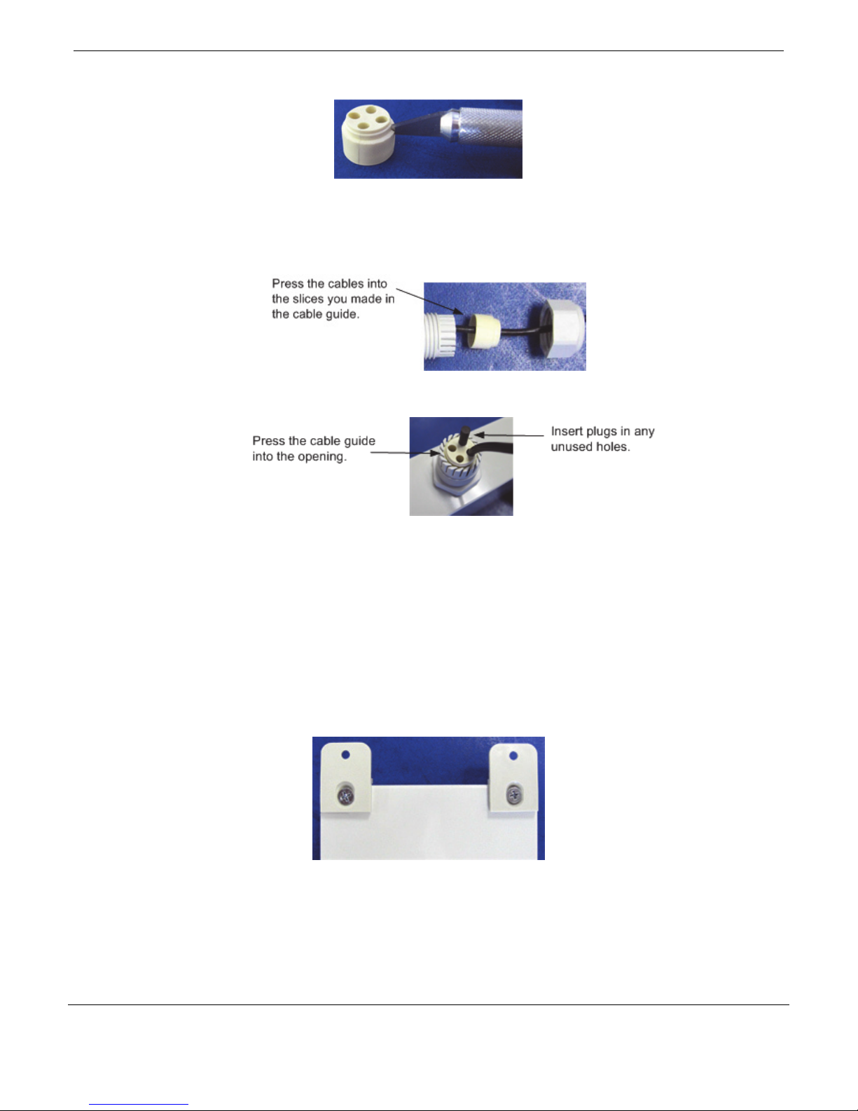
4. Cut slices into the cable guides for each sensor and the logger you will be connecting to the port.
5. Slide sensor cables through the dome nut and then through the opening in the case. The threaded side of the dome nut should be
facing towards the connector.
6. Plug the cables into the Smart Sensor port. Adjust the cable length as necessary so there is no excess cable inside the case.
7. Position the cable guide near the opening and press the cables into the slices in the cable guide.
8. Push the cable guide back into the case opening. Pushing the cable guide in at a slight angle and with a slight twist may help it slide in
more smoothly. Insert plugs into any unused holes in cable guide.
9. Screw the dome nut onto the case. Tighten by hand, and then an additional ½ to ¾ turn with an adjustable wrench. The dome nut
must be very snug.
10. Screw the clear cover back onto the case. Use a Phillips-head screwdriver to tighten the four cover screws.
Mounting
You can mount the case to a wall or other location for a permanent installation, with or without the mounting feet included with the
case.
With Mounting Feet
1. With a slotted screwdriver, screw the mounting feet onto the back of the case as shown below using the short flat-head screws in the
mounting kit provided with the case. There are holes pre-drilled on the back of the case for attaching the feet.
2. Once the feet are attached, screw in the longer screws through the holes in the mounting feet to the wall (or other location).
Without Mounting Feet
1. Remove the cover from the case.
2. There are four holes next to each of the four screw holes used to attach the clear cover. Screw in the four long Phillips-head screws
through the inside of the case to the wall (or other location).
3. Replace the cover.
© 2008–2015 Onset Computer Corporation. All rights reserved. Onset and HOBO are registered
trademarks of Onset Computer Corporation. All other trademarks are the property of their respective
companies.
Find Quality Products Online at: sales@GlobalTestSupply.com
www.GlobalTestSupply.com
12441-B MAN-S-ADAPT-6
 Loading...