

Onset hobo u30, HOBO U30 Station User Manual
Onset Computer Corp
Contacting Onset
For support, please contact the company that you bought the products from: Onset Computer
Corporation or an Onset Authorized Dealer.
Onset Computer Corporation
470 MacArthur Blvd.
Bourne, MA 02532
Mailing Address:
P.O. Box 3450
Pocasset, MA 02559-3450
Phone: 1-800-LOGGERS (1-800-564-4377) or 508-759-9500
Fax: 508-759-9100
Customer Service Hours: 8AM to 5PM Eastern Time
Technical Support Hours: 8AM to 8PM Eastern Time
Email: loggerhelp@onsecomp.com or hobolink@onsetcomp.com
Main Onset Web site: www.onsetcomp.com
Copyrights and Trademarks
© 2009–2011 Onset Computer Corporation. All rights reserved. Onset, HOBO, HOBOlink,
HOBOware, BoxCar, and FlexSmart are trademarks or registered trademarks of Onset
Computer Corporation for its data logger products and configuration/interface software.
Macintosh is a registered trademark of Apple, Inc. Microsoft and Windows are registered
trademarks of Microsoft Corporation. All other trademarks are the property of their respective
companies.
Doc#: 12269-I
Part#: MAN-U30-RC-UG
HOBO U30/RC - ii - User’s Guide

Onset Computer Corp
Contents
About the HOBO U30 Station .............................................................. 1
Introduction ................................................................................................................................................... 1
Key Features .................................................................................................................................................. 2
U30 Station Components .......................................................................................................................... 3
Software ........................................................................................................................................................... 5
Smart Sensors ................................................................................................................................................ 6
The Analog Sensor Port ............................................................................................................................. 7
Setup and Test ................................................................................... 9
Configuration Summaries ......................................................................................................................... 9
Initial HOBOlink Setup ............................................................................................................................ 11
Initial Hardware Setup ........................................................................................................................... 12
Connecting the HOBO U30 Station to HOBOware Pro ............................................................... 13
Configuring Analog Sensor Ports or a TRMSA Module .............................................................. 14
Changing the State of the U30 Relay Contact ................................................................................ 16
Basic Hardware Setup ............................................................................................................................. 17
Final HOBOlink Setup and Test ........................................................................................................... 18
Installing Mounting Plates .................................................................................................................... 19
Connecting Smart Sensors .................................................................................................................... 20
Connecting Analog Sensors................................................................................................................... 22
Connecting the Battery ........................................................................................................................... 23
Network Settings ............................................................................. 24
Configuring Wireless Network Settings .......................................................................................... 24
Configuring a Static IP Address ........................................................................................................... 28
Installing the U30 Station in the Field .............................................. 30
Field Installation Procedure ................................................................................................................. 30
Connecting Grounding Wire ................................................................................................................. 32
Installing Weatherproof Cable Channels ........................................................................................ 33
Connecting Solar or AC Power ............................................................................................................. 36
Connecting Equipment to the Relay Contact ................................................................................. 37
Mounting the HOBO U30 Station to a Pole ..................................................................................... 38
Checking Cellular Signal Strength (U30/GSM) ............................................................................. 39
HOBO U30/RC - iii - User’s Guide

Onset Computer Corp
The U30 Relay Contact ..................................................................... 40
An Overview of the U30 Relay Contact ............................................................................................ 40
Relay Example - Start Device ............................................................................................................... 42
Relay Contact Example - Stop Device ............................................................................................... 43
Configuring Relay Alarms for the U30/RC ..................................................................................... 44
Changing the State of the U30 Relay Contact ................................................................................ 46
Configuring Relay Alarms for the U30/RC ..................................................................................... 47
Maintenance..................................................................................... 49
General Maintenance ............................................................................................................................... 49
Adding a Sensor ......................................................................................................................................... 51
Removing/Replacing a Sensor ............................................................................................................ 52
Testing Smart Sensors ............................................................................................................................ 52
Checking the U30 Status ........................................................................................................................ 52
Inspecting the HOBO U30 Station ...................................................................................................... 53
Troubleshooting the HOBO U30 Station ......................................................................................... 54
The Smart Sensor Expander Board ................................................... 56
Opening the Secondary Cable Slot ..................................................................................................... 56
Installing the Expander Board ............................................................................................................. 58
The Battery ...................................................................................... 60
Overview....................................................................................................................................................... 60
Battery Life .................................................................................................................................................. 61
Maximizing Battery Life ......................................................................................................................... 62
Battery Voltage .......................................................................................................................................... 63
Connecting the Battery ........................................................................................................................... 65
Maintaining the Battery ......................................................................................................................... 66
Replacing the Battery .............................................................................................................................. 66
Troubleshooting the Battery ................................................................................................................ 67
Battery Life without External Power ................................................................................................ 68
Reference ......................................................................................... 69
General U30 Specifications ................................................................................................................... 69
GSM/Wi-Fi Specifications ...................................................................................................................... 71
Analog Sensor Port ................................................................................................................................... 72
Time Accuracy ............................................................................................................................................ 74
HOBO U30/RC - iv - User’s Guide

Onset Computer Corp
Memory ......................................................................................................................................................... 75
Connection Status LEDs ......................................................................................................................... 76
Logger Status LEDs ................................................................................................................................... 78
Items Required for Field Installation ................................................................................................ 79
Accessories .................................................................................................................................................. 80
FCC Part 15 Compliance ......................................................................................................................... 81
Wi-Fi Compliance ...................................................................................................................................... 82
Ethernet Compliance ............................................................................................................................... 83
Tripod Setup .................................................................................... 84
Guidelines for Typical Field Setup ..................................................................................................... 84
Field Preparation Checklist .................................................................................................................. 86
Items Required for Installation ........................................................................................................... 87
Task 1: Assemble Tripod ....................................................................................................................... 89
Task 2: Install Grounding Kit ............................................................................................................... 96
Task 3: Temporarily Install Upper Mast (Optional) ................................................................... 97
Task 4: Mount Cross Arm (Optional) ................................................................................................ 98
Task 5: Mount Upper Mast to Lower Mast ..................................................................................... 99
Task 6: Mount Logger to Upper Mast ............................................................................................. 100
Task 7: Install Guy Wire Kit (Optional) .......................................................................................... 101
Task 8: Position and Level Sensors ................................................................................................. 102
Task 9: Final Setup ................................................................................................................................. 103
HOBO U30/RC - v - User’s Guide

Onset Computer Corp
ABOUT THE HOBO U30 STATION
Introduction
Overview
The HOBO U30 Station is a data logging and monitoring device that can be easily reconfigured
and adapted to a wide variety of applications. Up to 15 channels of data can be recorded and
monitored remotely via HOBOlink™.
Use HOBOware® Pro software to set up analog data channels, communicate with the logger
locally, and perform advanced plotting and analysis.
The HOBO U30 Station is a data logging system that can be easily reconfigured and adapted to
a wide variety of applications. Up to 15 channels of data can be recorded and monitored with
HOBOware Pro software.
You can set alarms to trip for specific sensor readings that you select or for overall system
conditions, such as when the memory or battery is running low.
Remote Communication Models
The HOBO U30 Station is available in three models that support Remote Communication:
• GSM
• Wi-Fi
• Ethernet
Note: The HOBO U30/Wi-Fi works with all approved Access Point Router standards including
typical home IEEE 802.11b and IEEE 802.11g units. Pre-N and Draft-N access point routers are
‘preliminary’ and may not work with the HOBO U30/Wi-Fi.
Contents
The HOBO U30 Station package includes:
• HOBO U30 Station
• Mounting Kit
• Grounding Wire
• Cable Entry and Sealing Kit
• Optional Analog Sensor Port, if ordered
• Optional Sensor Expander Board, if ordered
1

Onset Computer Corp
Key Features
Remote Communication
There are three versions of the U30 that allow for remote communication using HOBOlink. By
using any web browser, you can configure and view data from the HOBO U30 Station anywhere
in the world.
• GSM. The HOBO U30/GSM contains a Global System for Mobile (GSM) communications
radio module that uses the mobile phone network to establish an internet connection
with HOBOlink.
• Wi-Fi. The HOBO U30/Wi-Fi combines ruggedized data logging hardware with
integrated Wi-Fi communications, and is versatile enough to use in both indoor and
outdoor environments. Users can easily and quickly plug in their choice of sensors and
connect to a Wi-Fi network without having to worry about cumbersome
communications cables or wiring.
• Ethernet. The HOBO U30/Ethernet allows you to connect directly to the internet using
an Ethernet cable.
Automatic Detection of Smart Sensors
The HOBO U30 Station automatically recognizes Smart Sensors. You can connect up to 10
Smart Sensors of any type or combination just by plugging them in before logging begins. No
programming, wiring or calibration is required to set them up. The connections between the
Smart Sensors and the logger are digital, ensuring accurate, reliable data collection and
storage. The HOBO U30 Remote Monitoring System is compatible with all Smart Sensors used
with the HOBO Weather Station and HOBO Micro Station.
Alarm Notification
The HOBO U30 Station supports alarm notification for sensors as well as system alarms. When
an alarm is detected, the system can trigger the relay contact closure and send you a
notification to your email/mobile phone. Alarms can be set for individual sensors and for
overall system conditions.
Rechargeable Battery
The HOBO U30 Station uses a Sealed Lead Acid battery that can be recharged via a solar panel
or AC adapter. This provides continuous power to keep the HOBO U30 Station recording and
transmitting data for years.
Optional Analog Sensor Ports
The HOBO U30 Station can be optionally configured with two analog sensor ports. The ports
are user-configurable and can accept and provide excitation power to a wide range of Onset
and third-party sensors with 0-20 V or 0-20 mA output. The Analog sensor ports are factoryinstalled.
2
Onset Computer Corp
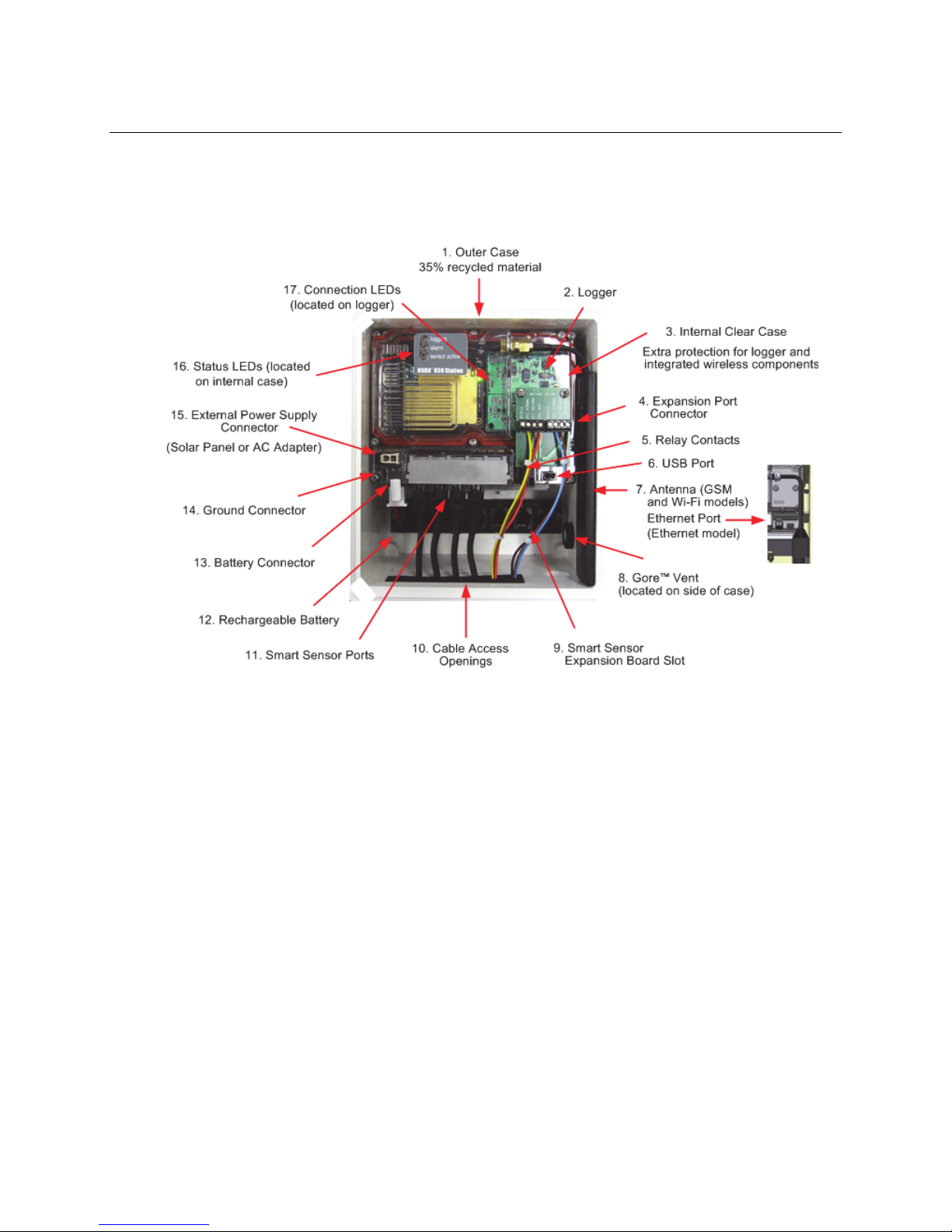
U30 Station Components
This topic describes the components for the HOBO U30 Station. Some components apply to
specific models only, as noted.
Diagram
Component Descriptions
1. Outer Case - Protects the U30 Station.
2. Logger - The U30 Station.
3. Internal Weatherproof Case – Provides a second level of protection for the U30
electronic circuitry.
4. Expansion Port Connector (shown with optional Analog Sensor Port installed) - This port
is where the optional Analog Sensor Ports are factory-installed.
5. Relay Contacts - The Relay can be activated, deactivated, or pulsed on user-defined
sensor alarms. The relay can be configured as normally open or normally closed, and is
rated for 30 V, 1 Amp maximum.
6. USB Port - Plug in a USB cable here to connect directly to a computer.
7. Antenna or Ethernet Port - Antenna installed on GSM or Wi-Fi models; Ethernet
Connection for the Ethernet model only.
8. Vent - This vent allows pressure to equalize inside the enclosure, but does not allow
liquid to pass through.
Figure 1: U30 Components
3

Onset Computer Corp
NOTE: The pressure inside the case does not match the outside air pressure exactly so a
barometric pressure sensor deployed within this case cannot measure the true
atmospheric pressure unless it has its own unrestricted vent to the outside.
8. Smart Sensor Expansion Slot - The optional Smart Sensor Expander Board is installed
here.
9. Cable access openings - All cables and wires are pulled through a protective rubber cable
channel placed in this opening. If using the optional factory-installed expander board for
additional Smart Sensors, you will need to use the second cable access opening.
10. Smart Sensor Ports - Connect up to five Smart Sensors in these RJ-12 jacks. Use one jack
to connect the optional expander board for additional Smart Sensors.
11. Rechargeable Battery - 4-Volt Sealed Lead Acid (SLA) battery located inside the case.
12. Battery Connector - Plug in the 4-Volt Sealed Lead battery here.
13. Ground Connector - Plug in grounding wire here to ground the system.
14. External Power Supply Connector - Plug in the compatible solar panel or AC adapter
here.
Important: Always connect or disconnect external power before the battery. Damage
may occur if the battery is unplugged before the external power is disconnected.
15. Internal Enclosure - provides a second weather-proof housing for the electronics in the
HOBO U30 Station. You should never open this case. Doing so will void the warranty.
16. Status LEDs
There are three Light Emitting Diode (LED) status indicators.
Logging indicates whether the system is currently logging.
Alarm indicates if an alarm has been tripped.
Sensor active indicates that Smart Sensor network communications are occurring.
For more information on LEDs, refer to Diagnostics and troubleshooting.
17. Connection LEDs (Remote Communication Models only)
Top - Blinks when the HOBO U30 Station is attempting to contact a network (cellular
tower, Wi-Fi, or Ethernet, depending on model).
Bottom - Blinks when the U30 is connected to HOBOlink.
4

Onset Computer Corp
Software
The HOBO U30/RC Station is designed primarily for use with HOBOlink, which allows for
continuous logging and transmission of data using remote communication technology. There is
some configuration however that requires HOBOware Pro software. Before you set up your
system, it is important to understand when to use HOBOlink and HOBOware Pro.
HOBOlink
• Launching the U30 Station
• Setting up readout schedules (connection intervals)
• Configuring Alarms
• Viewing Data
• Monitoring Status
See the HOBOlink Quick Start Guide and the HOBOlink Help for details.
HOBOware Pro
• Configuring the Analog Sensor Ports
• Changing the default system-wide relay operation (which is normally open)
• Testing individual Smart Sensors
• Plotting and analysis of datafiles
• Troubleshooting when there is no connection to HOBOlink
See the HOBOware User's Manual for details.
5

Onset Computer Corp
Smart Sensors
Description
Smart sensors plug into the logger and collect data about various parameters.
The HOBO U30 Station automatically recognizes Smart Sensors. You can connect up to 10
Smart Sensors of any type or combination just by plugging them in before logging begins. No
programming, wiring or calibration is required to set them up. The connections between the
Smart Sensors and the logger are digital, ensuring accurate, reliable data collection and
storage.
You do not have to stop the logger to add a new Smart Sensor. Simply connect the sensor and
then select Force Relaunch on Next Connection in the Launch Configuration panel in
HOBOware Pro.
Refer to www.onsetcomp.com for a current list of available sensors.
Cable Length
The HOBO U30 Station can work with a maximum total of Smart Sensor cable lengths up to 100
meters (328 feet), as measured from the logger connection point to the electronics embedded
in the individual cables. Optional Smart Sensor extension cable lengths must also be included
in the total. This limitation applies to Smart Sensor cables only. The lengths of other cables,
such as those connected to the Analog Sensor Port or the analog portion of smart sensor cables
do not need to be included in this total.
Data Channel Limitations
The HOBO U30 Station can log up to 15 data channels (not including the internal battery
channel). This includes the two channels in the Analog Sensor Port plus each of the Smart
Sensor channels (note that some Smart Sensors may have more than one channel). If you have
more than 15 channels connected, some of the sensors will be ignored. You should remove any
Smart Sensors that will not be used in the deployment, and disable the second channel in the
Analog Sensor Port if it is not needed (the first channel cannot be disabled). If you connect a
Smart Sensor that has multiple channels (such as temperature and relative humidity), all of its
channels will be logged. There is no way to disable them.
6

Onset Computer Corp
The Analog Sensor Port
The Analog Sensor Port is an easy-to-configure, flexible DC signal-conditioning option that can
be factory-installed in the HOBO U30 Station. This two-channel port can accept, and provide
excitation power to a wide range of Onset and third-party sensors with 0–20 V or 0–20 mA
output, including devices with 4–20 mA current loop interface, and sensors with 0–2.5, 0–5,
and 0–10 V DC output.
The Analog Sensor Port features input protection and signal filtering, as well as delta-sigma
A/D conversion and factory calibration. This port features extremely low power operation,
resulting in long battery life for unattended data logging applications. Precision electronics
provide ±0.25% accuracy from 50 mV to full scale (FS).
Sensors connected to this Analog Sensor Port can be configured using HOBOware Pro.
Configuration options include scaling parameters, and excitation power. See page 14, as well as
the HOBOware User’s Manual for configuration details.
If your HOBO U30 Station does not have an Analog Sensor Port and you wish to upgrade to one,
contact Onset Computer Corporation for information.
Sensor Excitation
The Analog Sensor Port supports optional, user-configurable sensor excitation power and
warm-up. Sensor excitation is a voltage output provided by the HOBO U30 Station to power a
sensor that is connected to it. This power may be needed because the sensor is not selfpowered, or because the sensor’s power capacity cannot support a long deployment.
When sensor excitation is required, the logger can provide 12 V DC sensor excitation voltage
up to 50 mA total for transducers that require external power for proper operation. The
excitation voltage has a programmable warm-up time and is controlled by the Analog Sensor
Port.
Excitation power can affect the battery life. If your sensor does not require it, you should not
include it in the channel configuration.
Modes
Carefully select the sensor excitation mode that best meets your needs.
• Warm-up mode
The logger supplies excitation power for a brief, user-programmable period prior to each
measurement. This mode allows you to select the minimum warm-up time needed to
allow for sensor stabilization, while conserving battery power.
For example, if you specify a warm-up of one second and set the Logging Interval to one
minute, the HOBO U30 Station will power the external sensor for one second, log a
measurement, and then turn off the excitation power for the next 59 seconds.
The warm-up time can be set from 5 milliseconds up to 120 seconds.
NOTE: If the warm-up time selected is greater than the logging interval selected, the
logger will interpret the excitation mode as continuous.
7

Onset Computer Corp
• Continuous mode
The logger supplies constant excitation power to the sensor for the entire duration of the
deployment. This mode will result in reduced battery life. Continuous mode is required if
the sensor needs more than two minutes of warm-up time. The Analog Sensor Port
begins functioning when logging begins.
When the ports are functioning correctly, the Active indicator LED on the port blinks
once per logging interval to indicate that a successful measurement has been made. The
Ex. On indicator LED will also be lit when excitation is enabled.
8

Onset Computer Corp
SETUP AND TEST
Configuration Summaries
This topic summarizes different paths you should take for HOBOlink and hardware
configuration depending on your U30 Station model and optional configuration you may need
to perform. These are not all of the possible scenarios, but the actual procedures will guide you
through any other variations you may have.
The hyperlinks below will open in a new window, so you will always be able to reference this
topic while you are viewing the detailed procedures.
GSM
U30/GSM Station with no Analog Sensors
Initial HOBOlink Setup (page 11)
Basic Hardware Setup (page 17), Steps 1-4
Final HOBOlink Setup and Test (page 18)
Wi-Fi
U30/Wi-Fi Station with DHCP and no Analog Sensors
Initial HOBOlink Setup (page 11)
Basic Hardware Setup (page 17), Steps 1-3
Configuring Network Setup (page 24), Steps 1-3
Basic Hardware Setup (page 17), Step 4
Final HOBOlink Setup and Test (page 18)
U30/Wi-Fi Station with Static IP and no Analog Sensors
Initial HOBOlink Setup (page 11)
Basic Hardware Setup (page 17), Steps 1-3
Configuring Network Setup (page 24), Steps 1-3
Basic Hardware Setup (page 17), Step 4
Final HOBOlink Setup and Test (page 18)
9

Onset Computer Corp
U30/Wi-Fi with DHCP and Analog Sensors
Initial HOBOlink Setup (page 11)
Basic Hardware Setup (page 17), Steps 1-3
Configuring Network Setup (page 24), Steps 1-3
Configuring Analog Sensor Ports or TRSMA Module (page 14), Steps 3-5
Basic Hardware Setup (page 17), Step 4
Final HOBOlink Setup and Test (page 18)
U30/Ethernet
U30/Ethernet Station with Static IP and no Analog Sensors
Initial HOBOlink Setup (page 11)
Basic Hardware Setup (page 17), Steps 1-4
Configuring a Static IP Address (page 29)
Final HOBOlink Setup and Test (page 18)
U30/Ethernet Station with Static IP and Analog Sensors
Initial HOBOlink Setup (page 11)
Basic Hardware Setup (page 17), Steps 1-3
Configuring a Static IP Address (page 29)
Configuring Analog Sensor Ports or TRSMA Module (page 14), Steps 3-5
Basic Hardware Setup (page 17), Step 4
Final HOBOlink Setup and Test (page 18)
10

Onset Computer Corp
Initial HOBOlink Setup
Before you connect the battery to the U30 Station, you should perform this procedure to setup
your HOBOlink account and perform initial configuration and testing for the U30.
For more details, see the HOBOlink Quick Start Guide and the HOBOlink Help.
Steps
1. Go to www.hobolink.com and create a HOBOlink account.
2. Activate your account by responding to the Activation e-mail.
3. Log into your HOBOlink account and register the U30 that you are configuring.
4. Configure the Logging Interval in the Launch Configuration pane.
For an initial test, configure a Logging Interval just long enough to record data that you
can verify. You will later change this to you required interval for deployment.
5. Configure the Connection Interval in the Readout Configuration pane.
For this test, you may want to configure a frequent Connection Interval so that you can
verify proper operation without having to wait as long for updates. For the U30/GSM,
this will be limited by the Fastest Connection Allowed by your Communication Plan. To
bypass your GSM Communication Plan restrictions for testing see below.
Once you confirm the readouts are occurring as they should, you can change the
Connection Interval to your desired on-going schedule for deployment.
NOTE: For testing, you can bypass your GSM Communication Plan restrictions by manually
connecting to HOBOlink using HOBOware Pro (direct connection using supplied USB Cable).
From the main menu select Status, and then click the Contact HOBOlink button. After the test,
disconnect the U30 from the computer. The U30 will connect to HOBOlink at the next
scheduled Connection Interval.
NEXT TASK: Initial Hardware Setup (page 12).
11

Onset Computer Corp
Initial Hardware Setup
Before you take the U30 Station into the field for deployment you should perform the following
preliminary hardware assembly and configuration:
• Basic Setup (Required)
• Network Settings (U30 Wi-Fi and Ethernet) (Optional)
• Analog Sensor Ports or TRMS Module (TRMSA-D)(Optional)
Everyone must perform Basic Hardware Setup first. Follow the procedure from there if you
need to configure Network Settings or Analog Sensor Ports/TRMS Module.
Before you Begin
This procedure assumes that you have already created a HOBOlink account and registered the
U30 Station. You should register the U30 Station before you connect the battery and have it
connect to HOBOlink. See Initial HOBOlink Setup on page 11.
Items for Setup
If you are using the Smart Sensor Expander Board
• Smart Sensor Expander Board
• Expander cable
• Bladed screwdriver or chisel and a file for removing cover of Secondary Cable Bay
If you are using Analog Sensors or Relay Contact
• Small flat-head screw driver
Start Here: Basic Hardware Setup (page 17)
12
Onset Computer Corp
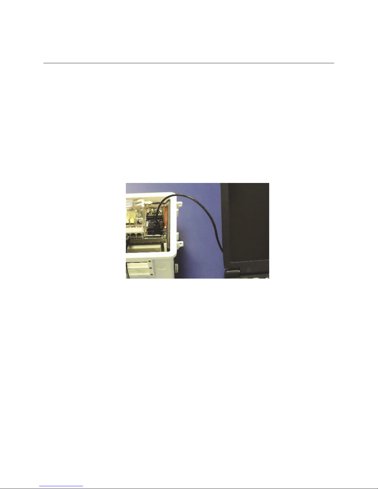
Connecting the HOBO U30 Station to
HOBOware Pro
This topic describes the procedure for connecting the HOBO U30 Station to HOBOware Pro. For
the HOBO U30/RC, you need to use HOBOware Pro to configure Analog Sensor
Ports/TRMSA Modules and to change the Relay Contact setting.
1. Connect to a computer.
To connect to a computer running HOBOware Pro, plug the “mini-USB” end of the USB
cable provided into the USB port on the HOBO U30 Station and connect the “A” end to the
USB port in your computer.
Important: If the USB cable is connected to the HOBO U30 Station at power up, it will
not make an immediate connection to HOBOlink.com. This allows you to use HOBOware
Pro without requiring you to override a connection to HOBOlink. If a connection with the
HOBO U30 Station is not initiated by HOBOware Pro within 10 minutes, it will attempt to
connect to HOBOlink automatically.
Figure 2: Connecting the U30 to a computer
If the device has never been connected to this computer before, it may take some time
for the computer to detect the new hardware and report that it has connected
successfully. One or more messages will appear, indicating that new hardware has been
found. You may also hear a chime.
NOTE: Your computer may tell you to reboot before you can use the device. It is not
necessary to reboot.
2. Run HOBOware Pro.
3. From the Device menu select Select Device ….
4. In the Select Device pane, click in the circle next to the desired device name and then
click OK.
When the device is recognized by HOBOware Pro, the status bar at the bottom of the
HOBOware Pro window will show the connection status.
13

Onset Computer Corp
Configuring Analog Sensor Ports or a
TRMSA Module
This is a branch of the Basic Hardware Setup procedure (page 17) for those who need to
configure Analog Sensor Ports or a TRMSA Module.
NOTE: If you need to configure network settings for the U30/Wi-Fi or the U30/Ethernet and
have not already, you should first perform Configuring Network Settings procedure on page 24.
Steps
If you are coming to this procedure from the Basic Hardware Setup procedure (page 17), start
at Step 1.
If you are coming to this procedure from the Configuring Network Settings procedure (page
24), start at Step 3.
1. Connect the U30 Station to a computer using the USB cable (page 13).
2. Connect the Battery (page 65).
NOTE: As long as your battery has adequate charge, you do not need to connect the solar
panel or AC adapter for this initial setup/test launch.
3. Launch HOBOware Pro.
4. From the Device menu, choose Configure Modules/Ports.
If the logger is already logging, you will be warned that the logger will have to be
stopped first.
The Select Channel to Configure dialog will appear showing all configurable Analog Sensors
attached to the logger.
5. Click on the + sign to expand the entry and show the channels.
Each channel in the module is defined by its channel number (the physical order in the module), the
configured channel name, and any location (assigned at launch) defined for this channel in the
logger.
NOTE: The default channel names Voltage and Current are just place holders and either channel can
be configured to measure voltage or current. For example, both channels can be used to monitor
sensors with 4-20 mA output.
6. Select a channel name and then click the Configure button to open the Channel
Configuration dialog.
7. Change any relevant configurable parameters. Refer to the HOBOware User’s Guide for
more details on this topic.
8. Save the Configuration (Optional). To send the currently displayed configuration to the
module/port, click Configure. The module will remain in this configuration until you
send it a different configuration.
9. Disconnect the USB cable from the U30 Station.
10. Reset the U30 Station by cycling power.
14

Onset Computer Corp
11. Disconnect the battery from the U30 Station and then reconnect it to cycle power.
The U30 Station will connect to HOBOlink at the next Connection Interval. Proceed to Final
HOBOlink Setup and Test (page 18).
15
Onset Computer Corp
Changing the State of the U30 Relay
Contact
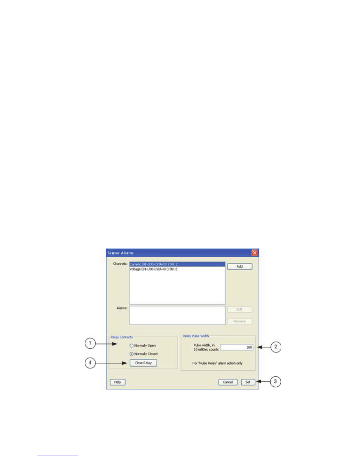
The U30 relay contact is a latching relay that can be configured as either Normally Open or
Normally Closed. The factory-default setting is Normally Open. You can change the default relay
settings in the Alarm dialog in HOBOware Pro.
Steps
This procedures assumes the U30 Station is connected to a computer running HOBOware Pro.
1. From the Device menu select Alarms to open the Alarms window.
2. In the Relay Contacts section, select Normally Open or Normally Closed.
Alternate Method: From the Device menu select Control U30 Relay > Set Default
(Deactivated) State and then select either Open or Closed.
3. If you are setting an Alarm Action of Pulse Relay, you can set the Relay Pulse Width.
The default is 1 s.
4. Click Set to send the alarm configuration to the U30 Station.
5. To test the relay, click the Close Relay or Open Relay button (button that appears
depends on which state the relay is in). You should hear a click in the HOBO U30 Station.
Click the button again to return to the default state. Use a digital multimeter to check for
continuity to confirm that the relay is opened and closed as expected.
Alternate Method: From the Device menu select Control U30 Relay > Activate Relay,
then select Deactivate Relay.
Figure 3: Testing the Relay
16

Onset Computer Corp
Basic Hardware Setup
Everyone must perform this basic hardware setup procedure first. If you need to configure
Network Settings or Analog Sensor Ports, follow the Procedure Branch in the procedure as
required for your U30 Station configuration.
Steps
1. Open Secondary Cable Slot (if applicable)
If a Smart Sensor Expander Board was factory-installed and you will be using those ports
now, you must open the Secondary Cable Slot. See page 56 for details.
If you are installing the Expander Board yourself, do that after you remove the
secondary cable slot. See page 58 for details.
2. Install Mounting Plates (page 19).
3. Connect Smart Sensors (page 20) and Analog Sensors (page 22).
Onset recommends that you test all sensors you plan to deploy with the logger.
NOTE: If you are using the Solar Radiation Shield, set up the Temperature and
Temperature/RH sensors. There are several small pieces required to connect these
sensors to the shield that could easily get lost in the field. It is strongly recommended
you install these sensors in the solar radiation shield before going to the field. See the
Solar Radiation Shield Manual for more information.
Procedure Branch
Option 1
If you need to configure Wireless Network Setup for the U30/Wi-Fi or U30/Ethernet, proceed
to Configuring Wireless Network Settings (page 24).
Option 2
If you do not need to configure Wireless Network Setup but you do need to configure Analog
Sensor Ports, proceed to Configuring Analog Sensor Ports (page 14).
Option 3
If you do not need to:
- configure Wireless Network Setup for the U30/Wi-Fi or U30 Ethernet, or
- configure Analog Sensor Ports
Continue with this procedure.
4. Connect Battery (page 65)
NOTE: As long as your battery has adequate charge, you do not need to connect the solar
panel or AC adapter for this initial setup/test launch.
The U30 Station will connect to HOBOlink at the next Connection Interval.
Proceed to Final HOBOlink Setup and Test (page 18).
17

Onset Computer Corp
Final HOBOlink Setup and Test
This topic describes the final HOBOlink setup and system test.
Before You Begin
This procedure assumes that you have completed the Initial HOBOlink Setup (page 11) and
Initial Hardware Setup (page 12).
Steps
1. If you are not logged into HOBOlink, log into HOBOlink now.
2. Perform additional HOBOlink configuration if required (Label Sensors, Configure
Alarms). See the HOBOlink Quick Start Guide or the HOBOlink Help for details.
3. Check the Device Status and the graphs to verify that sensors are reporting correctly and
the HOBO U30 Station is being readout properly.
4. When you are satisfied that the HOBO U30 Station and HOBOlink are working properly,
change your Logging Interval and Connection Interval to your desired settings for
deployment.
5. Repack the logger and sensors for transit.
Onset strongly recommends that you use the original packaging when possible because
it is custom-designed to protect the weather station and its components.
NEXT TASK: Installing the U30 Station in the Field (page 28).
18
Onset Computer Corp
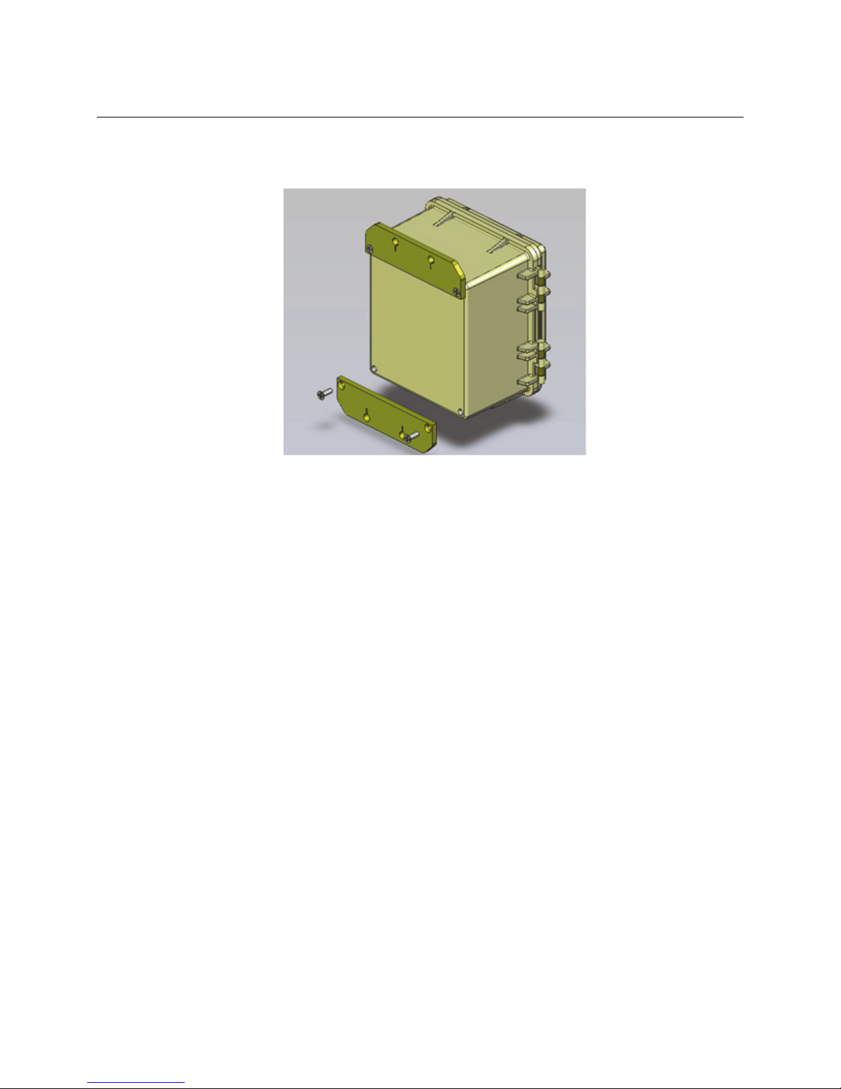
Installing Mounting Plates
Screw the mounting plates onto the back of the HOBO U30 Station case using a Phillips-head
screwdriver. Be careful to orient the plates as shown below so that the screw heads are sunk
into the screw holes.
Figure 4: Installing Mounting Plates
19
Onset Computer Corp
Connecting Smart Sensors
Before You Begin
• Connect Smart Sensors before you begin logging with the U30. Smart Sensors plugged in
after logging has already begun will be ignored.
• This procedure assumes that the Smart Sensor Expander Board and connector are
already installed. See page 56 for information.
Steps
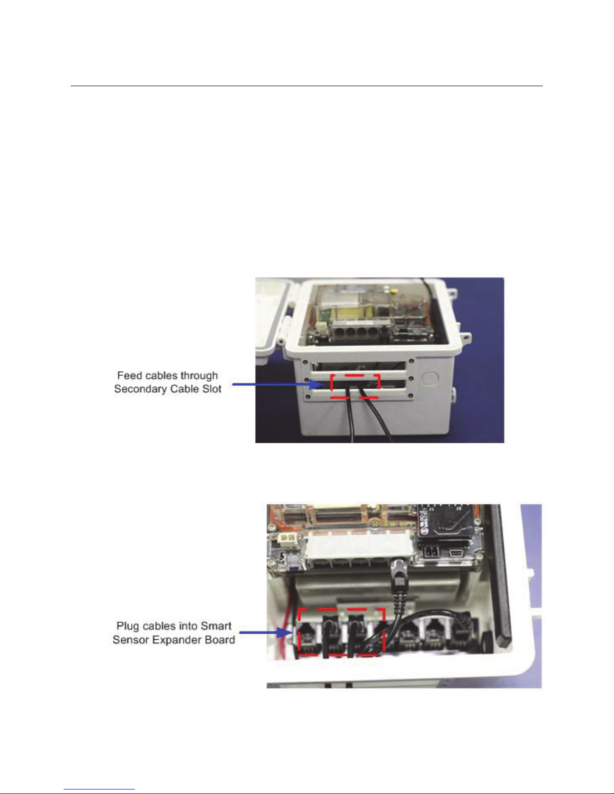
NOTE: If you are using the Smart Sensor Expander Board, connect sensors to those ports first.
1. Run cables through the Secondary Cable Slot.
Figure 5: Run Cables through Secondary Slots
2. Plug the cables into the Smart Sensor Expander Board.
Figure 6: Plug cables into Expander Board
20
Onset Computer Corp
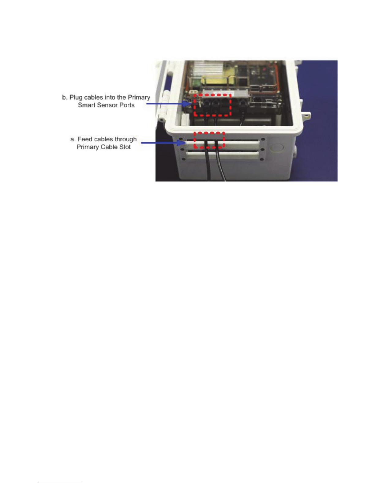
3. Run cables for remaining Smart Sensors through the Primary Cable Slots and connect the
cables into the Primary Smart Sensor Ports.
Figure 7: Plug Cables into Primary Slot
21
Onset Computer Corp
Connecting Analog Sensors
Refer to the specific sensor documentation for terminal connection details and use the pinout
diagram on page 72 to connect a two- or three-wire sensor or transducer to the module’s
terminals.
Figure 8: Connecting Analog Sensors
Steps
To make the connection:
1. Loosen the screw for each pin on the connector.
2. Insert the appropriate wire, which should be trimmed to 0.25 inches, ±0.04 inches of
bare wire exposed.
Make sure all wires attached to the Analog Sensor Port are routed through the cable
access opening.
3. Tighten the screw.
Note on Cables
To fit into the holes in the rubber cable channel, the ideal cable diameter is 0.157 in (4.0 mm).
If the cable is too small, build up the diameter using heat shrink. If it is too big and you are
using the secondary cable access opening, then place the cable through the left-most hole in the
rubber cable channel where the diameter can be up to 0.25 in (6.4 mm).
If you are not using the secondary opening or the cable is still too big, then splice on another
cable with a smaller diameter to fit through the hole. See the steps later in this section for
working with the rubber cable channel.
22
Onset Computer Corp
Connecting the Battery
This topic illustrates how to connect the battery to the U30 Station.
Before You Begin
NOTE: You should not connect the battery until you have performed Initial HOBOlink Setup
(page 11).
Illustration
Connect the built-in battery cable to the battery as shown below.
Figure 9: Connecting the Battery
23

Onset Computer Corp
NETWORK SETTINGS
Configuring Wireless Network Settings
This is a branch of the Basic Hardware Setup procedure (page 17), for those who need to
configure wireless network (WLAN) settings for the U30/Wi-Fi. Note that you will need to
change the settings every time you access a different wireless network.
IMPORTANT: If you are not familiar with network configuration, consult with your Network
Administrator or IT Department.
Steps
1. Download the HOBO NetSetup utility. Go to this URL and click the HOBO Network tab
to download the utility required for setting up your U30 Station to work with your
wireless network: http://www.onsetcomp.com/support/software_utilities
Note: The HOBO NetSetup Utility requires Microsoft .NET Framework (Version 4.0 or
above) installed. To determine if you have this installed on your computer, go to Start >
Control Panel > Add or Remove Programs to see if it is in the list of currently installed
programs. A link to .NET is also located at the same location as the HOBO NetSetup
utility.
2. Run HOBO NetSetup. Double-click the HOBO_NetSetup.exe file to run the HOBO
NetSetup utility.
3. Connect the U30 Station. Make sure the U30 is not powered (battery and/or AC
adapter cables should be disconnected). Connect the U30 Station to the computer with
the USB cable, then plug in the battery to power up the U30 Station. Click Begin in the
HOBO NetSetup utility.
24
Onset Computer Corp
4. Enter information about your Wi-Fi network. Complete the Basic Networking and
WIFI panels in the Network Configuration screen as explained below. If you are using a
U30/Ethernet, you only need to fill in the Basic Networking panel.
Basic Networking
By default, DHCP is set to Enabled, which is frequently used for small wireless networks.
If your network uses static IP addresses, set DHCP to Disabled and enter the following:
• IP Address: Use a unique address in the network.
• Gateway Address: The gateway address, or router, allows communication to
other LAN segments. The gateway address should be the IP address of the router
connected to the same LAN segment as the unit and it must be within the local
network.
• Netmask: The netmask defines the number of bits taken from the IP address that
are assigned for the host part.
Note: The unit’s configuration is stored in nonvolatile memory and is retained without
power. You can change the configuration at any time. The unit performs a reset after the
configuration has been changed and stored.
WIFI
You will need the network name, password, and settings to add the U30/Wi-Fi to your
network (you do not need to configure these settings for a U30/Ethernet model; click
25
 Loading...