

Page 1
HOBO® MicroRX Station (RX210x) Quick Start
Tools required:
• Phillips-head screwdriver for installing the water level sensor
(RX2103 and RX2104 models) or mounting the station to a flat
surface with screws.
• A ½ inch box wrench if you are using U-bolts to mount the station
to a tripod or mast.
• Other tools may be required depending on the accessories you
are using for your station deployment.
Log in to HOBOlink.
1
Go to www.hobolink.com and log in to an existing account or
create a new one. You’ll receive an email to activate the account.
Register the station.
2
In HOBOlink, click Devices, then RX Devices. Click the Register a
Device link. Give the station a name and enter the serial number
and device key from the label inside the station door.
Note: If you are using your own micro SIM card, follow the
instructions at www.onsetcomp.com/support/
manuals/23845-installing-micro-sim-rx2100-station before
continuing.
Mount the station.
3
There are three ways to mount the station using the built-in
mounting tabs. Note: You can also defer mounting until the end
of the process if you want to perform initial testing.
• Use the two sets of outer
holes and 1-5/8 inch saddleclamp U-bolts to attach the
logger to a tripod or mast
(this is the recommended
method for mounting on a
mast). Do not use U-bolts
without the saddle clamps
as that could bend the
mounting tabs and damage
the housing or compromise
the weatherproof seal. The
flat portion of the saddle
clamps should be against
the mounting tabs.
• Use the included cable ties
with the two sets of inner
holes to affix the logger to a PVC pipe or mast.
• Use the included screws and washers with the two sets of
outer holes to adhere the logger to a wall or flat surface.
Important: See the RX2100 manual for additional deployment
guidelines at www.onsetcomp.com/support/manuals/23808rx2100-manual.
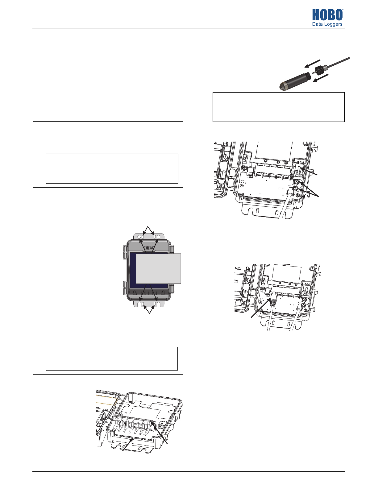
Remove the cable channel.
4
Remove the cable
channel making note
of how it is oriented.
Notch where the key on the
bottom of the cable channel
is installed
Inner mounting holes; use with
cable ties
Outer mounting
holes; use with
screws and washers
or saddle-clamp
U-bolts
Inner mounting holes; use
Cable channel
Install the water level sensor if applicable
5
(RX2103 and RX2104 models).
a. Insert the water level
sensor cable jack into the
water level sensor. Screw
on locking nut (hand tight).
Important: Make sure the O-rings on the cable jack end and
the cable and sensor mating housing surfaces are clear of any
debris. Any contamination of these surfaces can cause leaks
that may lead to sensor failure.
b. Plug the other end of the water level sensor cable into the port
on the right side of the board.
Plug the water
level sensor
cable into this
port
Secure the cable
with two screws
c. Use a Phillips head screwdriver to secure the water level sensor
cable in place with the two screws provided.
d. Route the cable through the far-right hole in the cable channel.
Plug in smart sensors if applicable.
6
a. Plug in smart sensors into the ports below the LCD.
Plug in smart sensors into
the five ports
b. Route the cables through the holes in the cable channel. There
are slits in the cable channel above each hole to guide the
cable into the hole. You may need to slightly bend the ends of
the channel to reveal the slits and push each cable into the
hole that lines up with the corresponding sensor connector.
Grease and reinstall the cable channel.
7
a. Use the integrated plugs to fill any unused holes. Bend the
plugs up to push them into the holes. Once a plug is partially
pushed through, you can pull on the part of the plug that is
inside the case. You may need to bend the ends of the channel
slightly to widen the holes for installing the plugs.
b. Lightly coat the portion of the sensor cables that will be in the
cable channel with a small amount of silicone grease (about the
size of a pea).
c. Lightly coat the bottom and two sides of the cable channel with
silicone grease.
d. Reinstall the cable channel in the station making sure the key
on the bottom is inserted in the notch in the station enclosure
as pointed out in step 4.
23807-B MAN-RX2100-QSG
Page 2
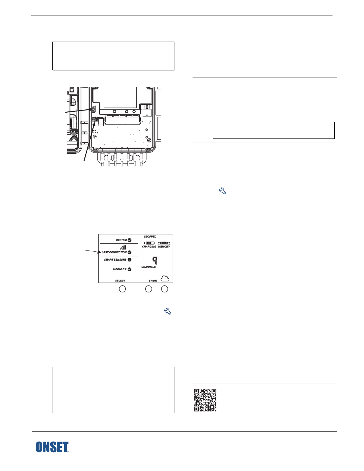
8
Plug in the battery and wait for the station
to connect to HOBOlink.
Note for RX2103 and RX2104 models: If you are using the
water level sensor, make sure it is plugged in before
powering up the station in this step. Otherwise, only
barometric pressure will be logged.
a. Plug in the battery cable. For RX2102 and RX2104 models,
plug in the solar panel cable for the built-in solar panel.
Plug in the solar
panel here (RX2102
and RX2104)
10
11
Start Logging.
Press the Start button on the station to start logging. The
station will connect to HOBOlink and then logging will begin.
If you are not using a water level sensor, then the setup is
complete. Measurements are uploaded to HOBOlink each
time the device connects. Go to www.hobolink.com and click
Help for details on checking the latest conditions, setting up
dashboards, exporting data, and more.
Obtain a reference water level reading
(RX2103 and RX2104 models).
Make sure the water level sensor is deployed in its final
location and that the station is logging. Take a reference level
reading, measuring the water level from the desired
reference point.
Important: Note the reference level reading as well as the
date and time it was taken.
Connect the
battery cable here
b. Once the battery cable is plugged in, “Initializing System”
will flash on the LCD. A checkmark appears next to
“System” after the station initialization is complete.
c. After the station powers up, it will connect to HOBOlink
automatically within two minutes. The cellular icon and
“Connection” will flash while the connection is underway.
Once the connection is complete, a checkmark appears
next to Last Connection. Note that the entire initialization
process may take several minutes; wait until Last
Connection and the checkmark appears before continuing
to step 9.
A checkmark
appears next to
Last Connection
after connecting
to HOBOlink
9
Configure the station in HOBOlink.
In HOBOlink, click Devices, then RX Devices, and click the
icon next to your station. Make changes and click Save on
each screen as you configure the following:
• General system settings (nickname, time zone, and
image)
• Readout settings (connection interval and night mode)
• Smart sensor logging and sampling interval
• Settings for each smart sensor (e.g. labels, graph, and
scaling)
Important for RX2103 and RX2104 models: Do not
configure the water level and water flow channels yet. Set
the logging and sampling interval for the water level
sensors module and optionally add labels, scaling, or
enable graphing. Continue to step 10 to start logging and
then obtain a water reference level reading in step 11
before configuring water level and water flow.
1-800-LOGGERS (564-4377) • 508-759-9500
www.onsetcomp.com/support/contact
12
Configure water level, water flow channels
in HOBOlink (RX2103 and RX2104 models).
© 2019 Onset Computer Corporation. All rights reserved. Onset, HOBO, and HOBOlink are registered trademarks of Onset
Computer Corporation. All other trademarks are the property of their respective companies.
This product has been manufactured by Onset Computer Corporation and in compliance with Onset’s ISO 9001:2015 Quality
Management System.
Perform the following steps in the field in HOBOlink with a
mobile device to verify that the system is logging the water
level correctly while you are still at the station site.
a. In HOBOlink, click Devices, then RX Devices, and click the
icon next to your station.
b. Under the water level sensors module in the Configuration
menu, select Water Level.
c. Click the checkbox to Enable Channel.
d. Click the checkbox to Enable Graph. Type a label (optional).
e. Enter the reference water level and date and time noted in
step 11.
• If the water level surface is below the reference point,
enter the reference water level as a negative number.
• If the water level surface is above the reference point,
enter the reference water level as a positive number.
f. Select the appropriate water density.
g. Click Save.
If you are configuring water flow and using one of the
supported weir or flume types, follow steps h–l.
h. Select Water Flow from the Configuration menu.
i. Click the checkbox to Enable Channel.
j. Click the checkbox to Enable Graph. Type a label (optional).
k. Choose the measurement method for water flow and
enter the appropriate information for the method
selected.
l. Click Save.
Water level and flow data will be calculated starting with the
next connection to HOBOlink. If you don’t want to wait for
the next scheduled connection, press the Cloud button on
the station LCD to connect to HOBOlink immediately. Note
that the reference water level information entered in this
step will not affect any previously logged data.
Go to www.hobolink.com and click Help for details on
checking the latest conditions, setting up dashboards,
exporting data, and more.
For additional information:
Station Manual for specifications and detailed operation,
including deployment and mounting guidelines, and more
information on water level sensor configuration. Go to
www.onsetcomp.com/support/manuals/23808-rx2100-manual
or scan the code at left.
See the HOBO MicroRX
23807-B MAN-RX2100-QSG
 Loading...