

Page 1

EG4xxx Owner’s Manual
Version 1.0
Onset Computer Corp
470 MacArthur Blvd
Bourne, MA 02532
www.onsetcomp.com
800-564-4377
loggerhelp@onsetcomp.com
April 18, 2018
Page 2
EG4xxx Owner’s Manual 2 INSTALLATION
1 Introduction
Thank you and congratulations to your purchase of an Onset EG4xxx device!
Properly installed, the device will be able to record and report energy usage and
production for years to come.
The first and second section of this manual describes installation and commissioning of the product. The third section provides operating instructions and is
followed by a section on equipment maintenance. The appendices provide the
device specifications and a reference to troubleshooting information.
2 Installation
Installation must be performed by a licensed electrician according to all applicable
local, national, and international codes.
CAUTION: The EG4xxx power connector carries high voltage. For safety,
the device must be installed in a suitably rated enclosure for the installation environment. The enclosure must have a screw-on or locking cover that prevents
accidental touch of the power connector.
2.1 What’s included in the box
• 1× EG4xxx device
• 1× AC Power plug (5-position plug)
• 1× DC Power plug (2-position plug)
• 0–30× Current transformers (CTs) w/ 8ft wires & plug (as ordered)
• 1× HomePlug AV wall-outlet adapter w/5ft Ethernet cable (if ordered)
April 18, 2018 2
Page 3

2 INSTALLATION EG4xxx Owner’s Manual
2.2 Materials required for installation
• Per phase: Use of proper smallest available breakers or rated fuse taps for
the install per local NEC rules. Usually 15A circuit breaker or single multipole breaker depending on phases used.
• Black, red, and white stranded AWG 12 wire; length depending on installation location. Thermal resistance to at least 75◦C. Blue wire is needed in
addition for 3-phase installations. Use wire that has insulation rating greater
than the max voltage inside the panel. Note: wire colors may vary based on
country and electrical service.
• Electrical tape
• Conduit and couplings as needed
• Mounting and wire organization hardware as needed
• If installed outside, appropriately rated enclosure (e.g. IPX4/NEMA4)
2.3 Tools required for installation
• #0 slotted screw driver (needed if length of CT-wires needs to be adjusted)
• Circuit-breaker finder (if using HomePlug power-line communication)
• Voltage meter
Additionally, for device commissioning and installation verification:
• Clamp-on AC current meter
• Laptop with Ethernet cable
2.4 Nomenclature and Symbols
In the US, residences typically receive power through split-phase power distribution which is provided through two hot legs, a neutral, and a protective ground.
Most commercial and industrial buildings receive power through 3-phase power
distribution provided through 3 hot phases, a neutral and protective ground.
3 April 18, 2018
Page 4
EG4xxx Owner’s Manual 2 INSTALLATION
Throughout the rest of this document, we use the term “phase” to refer both to the
phases of 3-phase power distribution as well as the two legs used in split-phase
power distribution.
The following table describes the symbols used on the device:
Symbol: Description:
Caution, risk of danger.
2.4.1 Measurement Category
Measurement Category III is for measurements performed in the building installation. Examples are measurements on distribution boards, circuit-breakers, wiring,
including cables, bus-bars, junction boxes, switches, socket-outlets in the fixed
installation, and equipment for industrial use and some other equipment, for example, stationary motors with permanent connection to the fixed installation.
2.5 Safety Warnings
Please follow the installation instructions in this manual for wiring diagram and
proper selection of CTs.
To reduce the risk of electric shock:
• Do not connect device to a circuit operating at > 277 Vrms to neutral.
• Always open or disconnect circuits from Power Distribution System of
building before installing or servicing the unit or attached current transformers.
2.6 Installation Location
The EG4xxx is usually installed near the power-distribution panel of a building,
where there is easy access to the power circuits to be measured.
April 18, 2018 4
Page 5
2 INSTALLATION EG4xxx Owner’s Manual
The EG4xxx is permanently connected equipment. A 15A circuit-breaker shall be
included (one per phase) in close proximity of the device and within easy reach
of the operator. The breakers shall be marked as the disconnecting device for
EG4xxx. The breakers shall be wired to the device in compliance with the NFPA 8
National Electrical Code using a conductor size of at least AWG12 and tightened
to 10 ft·lb.
The EG4xxx is a listed device and must be installed inside a suitable enclosure.
The enclosure the EG4xxx is installed in must be rated according to the environment it is used in. For example, outdoor installations require an outdoor-rated
enclosure (e.g., IPX4/NEMA4).
Select an installation location that is not exposed to direct sunlight or the elements.
Otherwise, the warranty may be voided.
Do not install the device in a way that would make it difficult to operate the disconnecting device (circuit breakers).
2.7 Device Overview
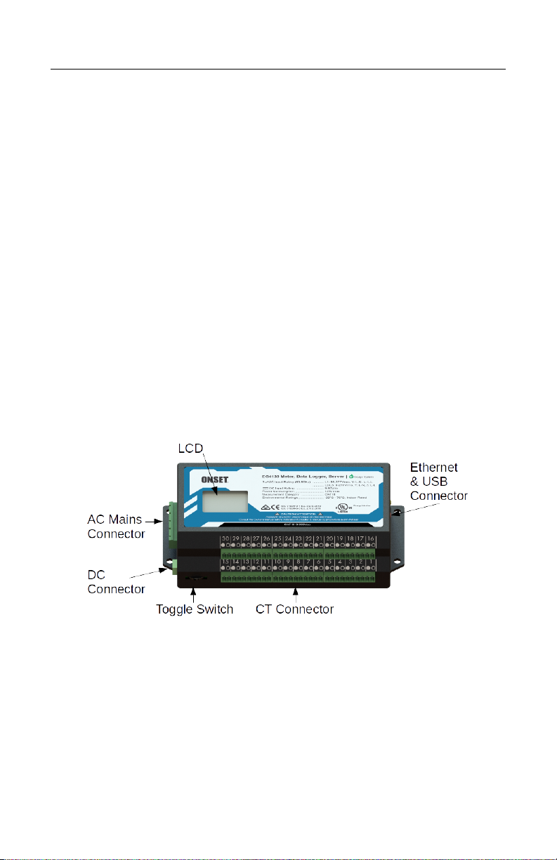
Figure 1: EG4xxx inputs and outputs
As shown in Figure 1, the EG4xxx has three input connectors: the AC Mains is a
5-pin connector used to wire the device to the building supply. The DC Connector
is a 2-pin connector for monitoring or powering from a DC voltage. The CT
Connector is used to connect current transformers (CTs) or other sensors. The
LCD and multi-switch provide some user interface.
5 April 18, 2018
Page 6
EG4xxx Owner’s Manual 2 INSTALLATION
The unit also has an Ethernet port (RJ45 connector) which can be used to hardwire the device to a Local Area Network (LAN). It also has two USB ports (TypeA Female) to interface to various other IT devices.
An LCD shows a basic user interface with readouts from the set variable registers.
It may be controlled through the multi-switch for basic control and configuration.
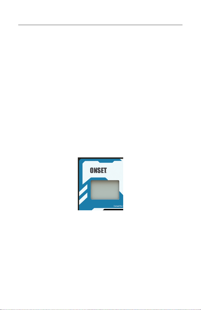
2.7.1 LCD
The LCD is an installation aid shown in Figure 2. When powered on, the LCD
will show a logo as the device boots. During this time the backlight will flicker
showing boot activity. Once the LCD shows the first register screen, the device is
automatically recording data if configured to do so.
Figure 2: EG4xxx LCD
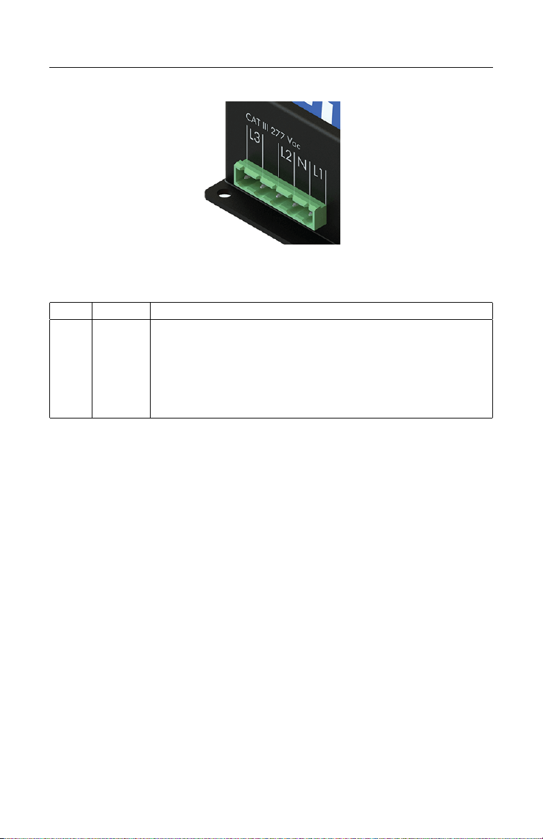
2.7.2 AC Mains Connector
This connector is shown in Figure 3 and the pin-out is as follows:
April 18, 2018 6
Page 7
2 INSTALLATION EG4xxx Owner’s Manual
Figure 3: AC Mains Connector
Pin: Name: Description:
1 L1 Wire to phase 1 of building supply.
2 N Wire to building’s Neutral.
3 L2 Wire to phase 2 of building supply for split- and three-phase
installs.
4 Unused. Leave unconnected.
5 L3 Wire to phase 3 of building supply for three-phase installs.
The AC Mains Connector is CAT III rated (for measurements performed in the
building installation, such as circuit breakers). Pin L1 serves three purposes: it
powers the device (2W typical, 12W maximum), the voltage on the line is measured to calculate power used/generated on phase L1, and it carries the powerline signal for communicating with the HomePlug AV wall-plug adapter. The pin
must be wired to the building’s power supply with a voltage in the range from 85–
277Vrms (to neutral). In contrast, pins L2 and L3 are used purely as voltage-taps
so power used/generated on phases L2 and L3 can be calculated. Wiring these pins
is necessary only if there are CTs measuring current(s) on L2/L3. The voltage on
these lines can be 0–277Vrms (Vac or Vdc).
To measure any signal on the AC Mains Connector L1 and N must be powered
with at least 85Vrms. If no voltage is supplied to this port, then the unit will
not measure any signal from L1, L2, or L3. The unit can continue to operate if
powered by the DC port.
2.7.3 DC Connector
This connector is shown in Figure 4 and the pin-out is as follows:
7 April 18, 2018
Page 8
EG4xxx Owner’s Manual 2 INSTALLATION
Figure 4: DC Connector
Pin: Name: Description:
1 + Wire to DC signal.
2 - Wire to ground.
The DC Connector CAT III rated for use from -60 – 60Vdc. It can measure the
voltage across that full range but if powered by the DC port, there must be at
least 9Vdc. If an installation utilizes both the AC Mains Connector as well as
DC Connector, and DC power is used to power the unit, there must be more than
12Vdc to ensure unit pulls power from the DC port.
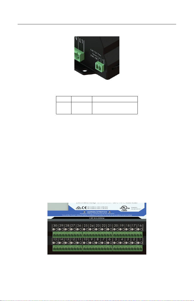
2.7.4 CT Connector
This connector is shown in Figure 5. It provides 15 or 30 positions for the CT
plugs illustrated in Figure 9. The silk-screened numbers indicate which CT should
be connected to which pair of pins. Pins that are to receive the black wire of the
CTs are marked with a circle with black interior, pins for the white wires are
marked with a circle with white interior.
Figure 5: CT Connector
April 18, 2018 8
Page 9

2 INSTALLATION EG4xxx Owner’s Manual
The CT Connector is rated for wiring one to thirty units of the CTs listed in Section B.6. The input voltage rating is 0.333Vrms at the rated current.
NOTE: There is no risk of damage if a CT plug is accidentally inserted such
that it straddles the pins for two different CTs. If this happens, the EG4xxx will
not be able to measure power properly but otherwise there are no ill effects. To
correct the problem, simply remove and re-insert the plug at the right position.
2.7.5 Ethernet (LAN) and USB Connector
This connector is shown in Figure 6. It provides hard-wired Ethernet connectivity
via an RJ45 plug and two USB host ports via Type-A Female plugs.
Figure 6: Ethernet Connector
The green LED in the top-left corner of the connector turns on (green) when an
Ethernet cable is plugged in and a valid Ethernet carrier signal has been detected.
The LED goes dark briefly whenever data is being exchanged over the cable. The
yellow LED in the top-right corner of the connectors is a speed indicator. It turns
on (yellow) operating at 100Mbps and is off (dark) when operating at 10Mbps.
9 April 18, 2018
Page 10

EG4xxx Owner’s Manual 2 INSTALLATION
The USB ports are USB2.0 compatible and can supply up to 1A at 5V. They may
be used with various supported IT devices such as RS485-to-USB converters or
WiFi adapters.
2.7.6 Multi-switch
Figure 7 is a close-up of the multi-switch. The user can slide the switch Left or
Right for navigation and push the switch into the unit to select.
Figure 7: Multi-Switch
The multi-switch can be used to navigate the LCD menu system. By default, any
action seen from the multi-switch will wake the backlight to ensure a viewable
interface.
2.7.7 Time Reference
During normal operation, the EG4xxx maintains accurate time by synchronizing
with an NTP server, such as one of the public servers available at ntp.org. Since
NTP provides atomic-clock accuracy, there is usually no need to set the time manually.
When the NTP server is not accessible, either temporarily (e.g., after a power failure) or permanently (e.g., at a remote site), the EG4xxx relies on a Super Capacitor
backed real-time clock to maintain proper time.
The backup is designed only to cover relatively short power outages. The Super
Capacitor takes about 5 minutes to fully charge, and will keep correct time for
approximately 8 hours without power.
When power is restored after such an event, the EG4xxx will attempt to restore
proper time via the NTP server. If unavailable, and the Super Capacitor is depleted, the device will fall back to using the time that was in effect when the last
April 18, 2018 10
Page 11

2 INSTALLATION EG4xxx Owner’s Manual
data item was recorded prior to the power failure. The proper time must then be
restored later on, either manually via the device’s Settings→Date & Time page
or by provisioning an NTP server that is accessible.
2.8 Wiring Diagram
2.8.1 Typical Residential (Split-Phase) Installation
Figure 8 is a schematic wiring diagram showing a typical split-phase installation
where the EG4xxx is used to measure the amount of power being supplied by the
power utility (CTs 1–2) and the power supplied by a single-phase solar inverter
(CT 3). For simplicity, circuit-breakers are not shown.
Figure 8: Wiring Diagram for a Typical Split-Phase Installation
2.8.2 Other Installations
For commercial three-phase installation as well as many other installation and
configuration-scenarios, please refer to the Configuration Guide and support page
at
http://www.onsetcomp.com/support/EG4100
11 April 18, 2018
Page 12

EG4xxx Owner’s Manual 2 INSTALLATION
2.9 Installation steps
1. If you are planning on using the hard-wired Ethernet port, skip to Step 3.
(a) Find a spot at the installation site that has both an available power
outlet and a nearby Ethernet port (for access to the LAN).
(b) Plug the HomePlug AV adapter into the outlet.
(c) Connect the HomePlug AV adapter to the Ethernet port with the sup-
plied Ethernet cable.
2. Use a circuit-breaker-finder to locate the breaker for the outlet into which
the HomePlug AV adapter is plugged into. Designate the breaker’s phase
as L1. In split-phase installations, label the other phase L2. In 3-phase
installations, label the other two phases L2 and L3 (order does not matter,
as long as the labeling is applied consistently throughout the installation).
3. Install the new breaker(s) in the power-distribution panel such that they provide access to all phases.
4. Open the breakers so there is no power on the breaker contacts.
5. Mount the EG4xxx inside a suitable enclosure near the power distribution
panel.
6. Wire the 5-position plug as follows:
(a) Black wire: pin labeled L1 to breaker for phase L1.
(b) White wire: pin labeled N to Neutral.
(c) Red wire: pin labeled L2 to breaker for phase L2.
(d) Blue wire: pin labeled L3 to breaker for phase L3 (3-phase installa-
tions only).
Note: Colors may vary based on country and electrical service type.
7. Insert the 2-pin CT plugs into the CT Connector on the EG4xxx and record
the amperage of the CT, the phase being measured, and the item being measured in the table in Appendix D.
NOTE: Ensure that the stickers on the CTs point towards what is being
measured.
April 18, 2018 12
Page 13

3 COMMISSIONING EG4xxx Owner’s Manual
Figure 9: Correct wiring for 2-pin CT plug
If it is necessary to shorten or lengthen the CT wires, ensure that the CT
wires are connected as shown in Figure 9.
8. Close the newly installed breakers. This should cause the EG4xxx to power
up and, within a few seconds, the LCD will illuminate and show a logo.
Once the screen changes to the first register readout, the measurements have
started. The user can use the screen to verify a network connection.
9. Label the newly installed breakers as “EG4xxx Meter Disconnect” so the
customer can readily find them if it becomes necessary to power-cycle or
turn off the EG4xxx device for any reason.
IMPORTANT: Labeling the breaker(s) is essential. Do not skip that step.
Occasionally, it may be necessary to power-cycle the device. The breaker(s)
provide the only safe way to do that, so for safety-reasons, it is important that
the end-customer is able to identify the EG4xxx breaker(s) without having to
open any enclosures.
3 Commissioning
After installation, it is essential to verify that the device is operating properly and
measuring the expected quantities. Each device ships with a default configuration
that may or may not match your installation situation. In general, it is therefore
necessary to adjust the settings to match your situation. Please see the Configuration Guide for details.
For revenue-grade accuracy compliance, the EG4xxx must be paired with revenuegrade CTs tested and supported by the manufacturer.
13 April 18, 2018
Page 14

EG4xxx Owner’s Manual 4 OPERATION
Use a laptop or another computer to connect to the device’s built-in web-server
(see next section). Then, as described in the Configuration Guide, Tools→Chan-
nel Checker can be used to confirm that:
1. All voltages have the expected values (use voltage meter to verify).
2. All CTs report the expected currents (use clamp-on current meter to verify).
3. CTs are indeed installed on the phases set under Settings→Installation.
The voltage between the wire that the CT is clamped onto and the powerplug pin (L1-L3) that corresponds to the phase it is configured for should
be zero Volts.
4. All reported power values have expected polarity and power-factors. As a
general rule, EG4xxx convention requires that power coming into the site
shows as positive values and power being consumed at or diverted from the
site shows as negative values.
Also confirm that the EG4xxx dash-board shows a red line for total consumption.
Assuming all power coming into a site is measured by the device, this line should
never dip into the negative. As a final check, it is helpful to turn on and off some
large loads to confirm everything operates as expected. If there is a renewable
energy system on site, turning it on/off should not appreciably affect the red line
(total consumption).
4 Operation
4.1 Accessing your EG4xxx for the first time
Once the EG4xxx is installed, you can access it from any computer on your Local
Area Network (LAN) with a compatible web-browser (see spec-sheet). To start,
enter the following Web address into your web-browser:
Microsoft Windows: http://devname/
All other computers: http://devname.local/
where devname is the name of the device (e.g., Onset9999).
April 18, 2018 14
Page 15

4 OPERATION EG4xxx Owner’s Manual
For example, to access device Onset9999, you would enter the following URL
into your browser:
Microsoft Windows: http://onset9999/
All other computers: http://onset9999.local/
You may also use the LCD display to find the local IP address of the EG4xxx
on the network. Use the multi-switch on the main register display to scroll to
the last page containing the hostname and IP address of the EG4xxx. It will also
periodically display as the register screen changes. Visit the IP address in a webbrowser, for example, http://192.168.2.120/.
An example of the EG4xxx dashboard can be seen in Figure 10. Online help is
available via the Help link at the top-right of the dashboard.
4.2 Accessing your EG4xxx from the Internet
To access the EG4xxx from the Internet, open a compatible web-browser and then
visit the Web page at http://devname.meter.onsetcomp.com/ where
devname is the name of your device (e.g., “Onset9999”). If you receive a ”Not
Found” error, the meter has not yet connected to the Internet proxy server. Verify
the unit is powered and confirm network connectivity by accessing locally by
following 4.1, Accessing your EG4xxx for the first time.
You can also use the above URL as an alternative means to connect to your device
directly through your LAN. To accomplish that, click on the LAN Access link on
the top right of the page, once the device’s dashboard has loaded. This directs
your browser to access the device directly (through your LAN rather than going
through onsetcomp.com). This is both faster and allows you to access the
device even at times when your Internet-connection may not be working properly.
Please bookmark the address displayed in the browser after the page referred to
by the LAN Access link has finished loading.
15 April 18, 2018
Page 16

EG4xxx Owner’s Manual 4 OPERATION
Figure 10: EG4xxx dashboard
April 18, 2018 16
Page 17

4 OPERATION EG4xxx Owner’s Manual
NOTE: From time to time, the address of your EG4xxx may change and the
bookmark will stop working. Should this happen, repeat the above steps and
update the bookmark with the new address. Usually, this happens infrequently,
if at all. However, since it can happen, we recommend using the connectionmethods described in the previous section whenever possible. Alternatively, a
static (fixed) address can be configured for the device. See the next section for
details.
4.3 Configuring a Static IP Address
The EG4xxx normally automatically obtains its IP address and associated information through a service called Dynamic Host Configuration Protocol (DHCP). If
you cannot or do not wish to run this service on your LAN, the device will default
to using IP address 192.168.1.88, so the device can be accessed as:
http://192.168.1.88/
Your computer’s IP address must be configured to be on the same range as this
default address. If another device ends up using the same address, or a static IP
address is required, you may configure one from Settings→Network Settings.
4.4 Verifying the Proper Time
When the Internet is not available to the EG4xxx, it may be necessary to set the
date and time manually. To verify that the EG4xxx has the proper time, use a
browser to go to the device’s dashboard (see previous sections), then click on
Settings, then on Date & Time. If the displayed date and/or time is wrong, please
enter the correct values and then click on Save. Please repeat this step from time
to time, especially after prolonged power outages lasting more than a few hours.
4.5 Passwords and Saving Settings
By default, changes may be made using user-name owner and password default.
You must connect to the EG4xxx directly over the local network before making changes. This can be accomplished by clicking the LAN Access link in the
17 April 18, 2018
Page 18

EG4xxx Owner’s Manual 5 MAINTENANCE
upper-right hand menu on the EG4xxx main interface. Credentials and remote
administration can be managed in Settings→Access Control.
5 Maintenance
The EG4xxx is designed to be maintenance free. No preventive maintenance or
inspections are required.
Should it become necessary to clean the EG4xxx, disconnect it from the building
supply by turning off the breakers labeled “EG4xxx Meter Disconnect”, remove
the device, and clean it with a soft cloth. If a cleaning fluid is needed, use 70%
isopropyl alcohol. Wait until all cleaning fluid has evaporated before reinstalling
the device and turning the breakers back on.
The device has no replaceable batteries and no replaceable fuses.
CAUTION: If the equipment is used in a manner not specified by the manufacturer, the protection provided by the equipment may be impaired.
April 18, 2018 18
Page 19

A EMI COMPLIANCE EG4xxx Owner’s Manual
A EMI Compliance
A.1 FCC Compliance Statement
This equipment has been tested and found to comply with the limits for a Class B
digital device, pursuant to part 15 of the FCC Rules. These limits are designed to
provide reasonable protection against harmful interference in a residential installation. This equipment generates, uses and can radiate radio frequency energy and,
if not installed and used in accordance with the instructions, may cause harmful
interference to radio communications. However, there is no guarantee that interference will not occur in a particular installation. If this equipment does cause
harmful interference to radio or television reception, which can be determined
by turning the equipment off and on, the user is encouraged to try to correct the
interference by one or more of the following measures:
• Reorient or relocate the receiving antenna.
• Increase the separation between the equipment and receiver.
• Connect the equipment into an outlet on a circuit different from that to
which the receiver is connected.
• Consult the dealer or an experienced radio/TV technician for help.
CAUTION: Changes or modifications to the equipment not expressly approved by the manufacturer could void the user’s authority to operate the
equipment.
A.2 Canada ICES-003 Compliance
CAN ICES-3 (B)/NMB-3(B)
19 April 18, 2018
Page 20

EG4xxx Owner’s Manual B SPECIFICATIONS
B Specifications
B.1 Applicable Model Numbers
This manual applies to all EG4xxx models ranging from EG4000 through EG4999.
B.2 Electrical Rating of the Product
• AC Mains Connector: 85-277Vrms, 1-3 phases, 50-60 Hz, 12W peak (2W
typical).
• DC Connector: 9-60Vdc, 12W peak (2W typical).
B.3 Environmental Conditions
Suitable for indoor and outdoor use (with proper enclosure), Pollution Degree 2,
Measurement Category III. Not to be used at altitudes above 4000m. Voltage
fluctuations not to exceed ±10%. Temperature range: -30 – 70◦C (-22 – 158◦F).
Maximum relative humidity 80% up to 31◦C, decreasing linearly to 50% at 40◦C.
B.4 CE Immunity Statement
Performance criteria: At field-strengths up to 10V/m, no change of state or stored
data, may exhibit temporary variation in analogue input values.
B.5 Regulatory Certificates
UL File Number E344051
IEC/UL 61010-1 Ed. 3.0 B:2010
FCCs Title 47 CFR Part 15 Subpart B Class B
ICES-003 Information Technology Equipment Class B
IEC 61000-6-1 Ed. 3.0 B:2016
IEC 61000-6-3 Ed. 2.1 B:2011
RCM
April 18, 2018 20
Page 21

C TROUBLESHOOTING EG4xxx Owner’s Manual
B.6 Current Transformers (CT)
The EG4xxx is a Listed Device, certified to be used with Listed CTs. The CTs
sold by the manufacturer have been evaluated to ensure correct performance.
The current sensors may not be installed in a panel where they exceed 75% of the
wiring space of any cross-sectional area within the panel, in accordance with NEC
sections such as 312.8 and 366.9, as well as Articles 300 and 408.
C Troubleshooting and Support Information
Technical Support is available at:
http://www.onsetcomp.com/support/EG4100
Phone: 800-564-4377
Email: loggerhelp@onsetcomp.com
21 April 18, 2018
Page 22

EG4xxx Owner’s Manual C TROUBLESHOOTING
C.1 Default Installation Checklist
The EG4xxx needs to be configured for the environment it is installed in. Most
EG4xxx will have default settings for two 100A CTs monitoring Grid in CT ports
1 and 2, and a 50A CT monitoring L1 of the solar inverter in CT3. The installation information sheet included with the EG4xxx will have the default configuration printed on it. Your EG4xxx must be configured for its specific environment
through Settings→Installation.
Below is a brief checklist for the above stated installation. This only applies to
the split-phase backfed-breaker setup depicted in Figure 8.
100A Grid CTs (ports 1 and 2) have stickers facing toward utility.
50A Solar CT (port 3) has sticker facing toward inverter.
Voltage between conductor through CT1 and the L1 terminal reads 0V.
Voltage between conductor through CT2 and the L2 terminal reads 0V.
Voltage between conductor through CT3 and the L1 terminal reads 0V.
Black wires on CT leads line up with black circles on CT terminals.
EG4xxx Breaker disconnect labeled “EG4xxx Meter Disconnect”.
If applicable, the HomePlug adapter is connected directly in a wall outlet,
within 50-100 feet of the EG4xxx main unit, and is on the same phase powering
L1 of the EG4xxx.
EG4xxx Status is verified through LCD or loading the default webpage.
April 18, 2018 22
Page 23

D INSTALLATION INFORMATION EG4xxx Owner’s Manual
D Installation Information
Device Location:
Device Name:
Voltage Configuration:
Device Login:
Device Password:
Notes:
23 April 18, 2018
Page 24

EG4xxx Owner’s Manual D INSTALLATION INFORMATION
CT # CT Model Phase Measured item
1
2
3
4
5
6
7
8
9
10
11
12
13
14
15
16
17
18
19
20
21
22
23
24
25
26
27
28
29
30
April 18, 2018 24
 Loading...