

Page 1
2-Zone Remote Alarm (ARA) User’s Manual
The Remote Alarm is a battery-powered remote alarm device with audio and visual alarm indications. The Remote
Alarm is compatible with alarm outputs having passive relay contacts.
IMPORTANT INSTRUCTIONS FOR USE: THE REMOTE ALARM IS NOT INTENDED FOR AND SHOULD NOT BE USED IN
APPLICATIONS INVOLVING LIFE THREATENING OR LIFE SUPPORT SITUATIONS.
The ARA Remote Alarm does not operate without working batteries. Alarm function will not work if the batteries are
removed from the unit, or if the batteries fail. Please check the batteries and test the alarm function regularly.
Although the ARA and all its parts have passed all factory tests and are designed to be as reliable as possible, any of
these parts could fail at any time.
Specifications
Number of Inputs 2
Alarm Output Compatibility Normally Closed (NC) or Normally Open (NO) passive relay outputs, with
2-Zone Remote Alarm
(ARA)
Included Items:
• 4 mounting screws
• 1-inch connecting wire
• 3 AAA batteries
• blank labels
Input Wire 20 to 30 AWG, solid or stranded
Audible Alarm Level (Jumper
Select)
Operating Temperature Range -20° to 50°C (-4° to 122°F)
Operating Humidity Range 0 to 95% RH, non-condensing
Batteries 3 AAA, user replaceable
Battery Life Normal operation: 1 year; Alarm condition: 3 days
Size 111.8 x 83.9 x 40.7 mm (4.4 x 3.3 x 1.6 inches)
Weight 168 g (5.9 oz) with batteries
Shock Resistance 6-foot drop
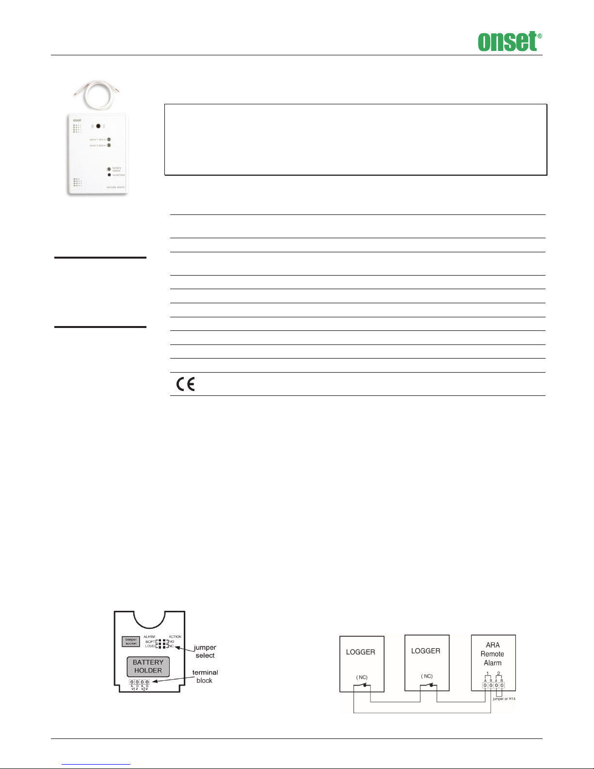
Setup and NO/NC Configuration
The Remote Alarm requires three AAA alkaline batteries for operation
(batteries included). Before installing the batteries, the Normally
Open/Normally Closed (NO/NC) jumper must be in the correct
position.
The NO/NC jumper configuration is only checked when the batteries
are installed. If the jumper setting requires changing, the batteries
should be removed then reinstalled after the change.
Remove the four screws in the back of the case with a Phillips-head
screw driver. There is a jumper strip labeled NO (Normally Open) and
NC (Normally Closed) near the top of the board (see Figure 1). The
jumper is in the NC position when shipped from the factory. Put the
jumper in the position corresponding to the alarm output
characteristics of the device to which the Remote Alarm will be
connected. Normally Open operation is used with alarm contacts that
are normally open and closed in alarm conditions. Conversely, Normally
Closed operation is used with alarm contacts that are normally closed
and open in alarm conditions. The jumper setting applies to both zones;
they are not individually selectable.
contacts rated for a minimum 5 volts DC and 5 microamps
Loud: 92 dBA @ 30 cm
Soft: 78 dBA @ 30 cm
The CE Marking identifies this product as complying with all relevant
directives in the European Union (EU).
Audio Beeper Volume
The beeper volume can be adjusted by moving the jumper on the
jumper strip labeled LOUD and SOFT (see Figure 1). The jumper is in the
loud position when shipped from the factory. If no beeper indication is
desired, the connector plug attaching the beeper to the circuit board
may be disconnected.
Zone Connection
Using a small (jeweler’s) regular flat head screwdriver, loosen the
screws for the desired zones on the screw terminal block and insert the
interconnect wires. Then tighten the screws until a moderate tug does
not pull the wires loose.
If you are using only one zone and are in the Normally Closed (NC)
mode, a jumper wire must be installed into the unused channel;
otherwise that zone indicator will always be flashing and will
significantly diminish the expected battery life.
Connecting Multiple Logger Alarm Outputs into a Single
Zone Input
You can connect multiple logger alarm outputs into one zone input as
long as they are all of the same type (NO or NC) and are connected
properly. The connections depend on whether the devices are NO or
NC.
Figure 1
5868-B Remote Alarm MAN
Figure 2: Normally Closed (NC) multiple logger configuration
Page 2
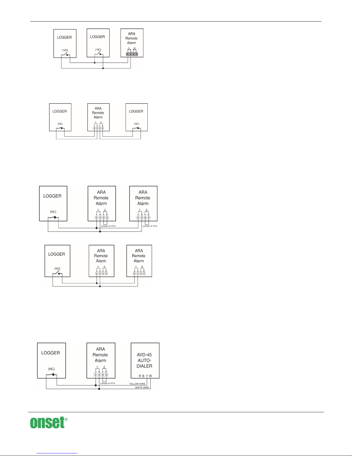
Figure 3: Normally Open (NO) multiple logger configuration
2-Zone Operation
If you are configuring the system for alarms in two zones, both zones
must be of the same type (NC or NO).
Figure 4: 2-zone logger inputs in NC configuration
Connecting Multiple Remote Alarms to One Logger
Alarm output
Up to two Remote Alarms may be connected to a single logger alarm
output as shown below. A total of 1000 feet of wire maximum (30 AWG
minimum) may be used to interconnect the Remote Alarm(s).
2-Zone Remote Alarm (ARA) User’s Manual
Battery Installation and Test
After the jumpers have been set and the zone inputs connected, the
batteries can be installed in the battery holder. Please note the proper
directions of the batteries as indicated in the holder. As the batteries
are installed, the alarm will beep three times and the Zone LEDs and
the RED battery status LED will flash three times.
Reassemble Case
Once the jumpers are set and the interconnect wires and batteries are
installed, the back should be attached to the case with the four screws.
Remote Alarm Wall Mount Instructions
1. Slide down wall mount bracket from rear of case to remove.
2. With countersunk holes facing you, position bracket in desired
location and attach with (4) flat head screws provided. If
attaching to a surface harder than drywall, it is recommended
that you drill (4) small pilot holes first.
3. To attach Remote Alarm, slide it down onto the wall-mounted
bracket.
Remote Alarm Testing
In order to test the ARA’s audio and visual indicators, press and hold
the MUTE/TEST button for one second. All three LEDs should flash red
three times as the audio indicator beeps three times. This operation,
however, does not test the ARA’s alarm signal detection circuitry. To
test the detection circuit, disconnect the alarm input wires. If the ARA is
configured as Normally Closed, this will set off the alarm. If the ARA is
configured as Normally Open, manually shunt (jumper) the inputs (1A
to 1B and 2A to 2B) and the alarm will be set off. If the ARA fails this
test, contact Onset Computer or an Onset authorized dealer.
More extensive system testing may be possible by simulating an alarm
condition at the monitoring unit which would initiate an alarm. For
additional information, refer to the manual for the monitoring unit.
Figure 5: NC multiple Remote Alarm configuration
Figure 6: NO multiple Remote Alarm configuration
It is imperative that the A side of the terminal block be connected to
the A side in multiple Remote Alarm hook-ups (and B side to B side).
Failure to do this will cause the remote alarm units to malfunction. If
the Remote Alarm is used with the AVD-45 AutoDialer, then be certain
the white and yellow wires are connected as shown below. The AVD-45
AutoDialer requires a Normally Closed relay setting for the logger
and/or Remote Alarm (see AVD-45 manual).
Figure 7: NC Remote Alarm/Logger/AutoDialer configuration
Operating and Battery Status
The battery-powered Remote Alarm shows its current operating and
battery status with a bi-color LED. This LED, when flashing green,
indicates normal operation and good batteries. When it is flashing red,
and the beeper is chirping, the unit is still operating, but the batteries
require replacement. If the LED is not flashing at all, the batteries are
dead and the unit is not operating. As long as the LED is flashing green,
the batteries still have enough capacity to signal an alarm condition
continuously for at least three days.
The Remote Alarm requires three AAA batteries. Use only fresh alkaline
batteries. Batteries can be changed without disconnecting the alarm
wires. See the Battery Installation and Test section for instructions.
Alarm Indications
If the Remote Alarm detects an alarm condition, the LED(s) for the
appropriate zone(s) will flash and the beeper will sound simultaneously
for about 0.5 seconds on and 1.5 seconds off.
Beeper Mute
If, during an alarm or low-battery condition, it is desired to mute the
beeper, press the mute/test button for one second and the beeper will
be silenced. If the alarm signal is removed, the audio indicator is
automatically reset and will sound again on the next alarm condition.
The mute function will also automatically reset approximately fifteen
minutes after the mute button was last pushed or immediately if a new
alarm condition has been detected.
The zone alarm LED(s) are not affected by the mute button and will
continue to flash during an alarm.
1-800-LOGGERS (564-4377) • 508-759-9500
www.onsetcomp.com • loggerhelp@onsetcomp.com
© 2011 Onset Computer Corporation. All rights reserved. Onset and
HOBO are trademarks or registered trademarks of Onset Computer
Corporation. All other trademarks are the property of their
respective companies.
5868-B Remote Alarm MAN
 Loading...