

Page 1
NUF4001MU
9
l
s
4-Channel EMI Filter with
Integrated ESD Protection
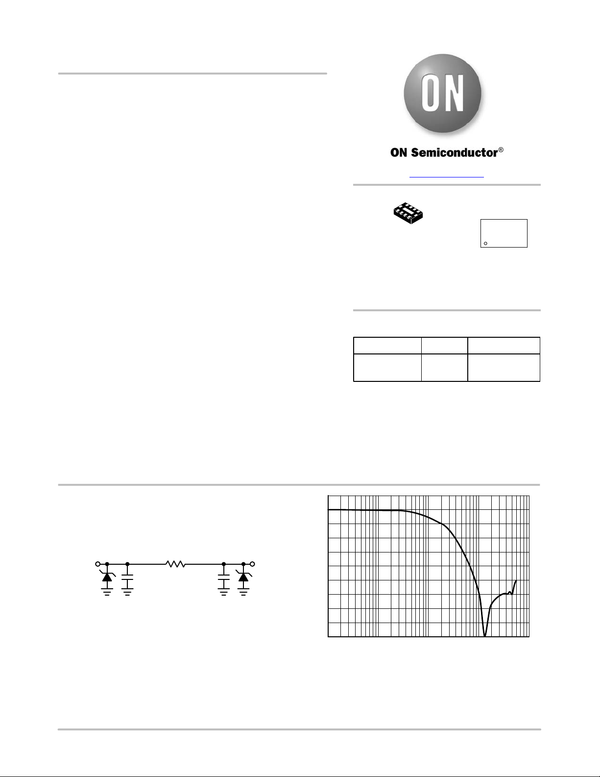
The NUF4001MU is a four−channel (C−R−C) Pi−style EMI filter
array with integrated ESD protection. Its typical component values of
R = 100 and C = 13 pF deliver a cutoff frequency of 150 MHz and
stop band attenuation greater than −25 dB from 800 MHz to 5.0 GHz.
This performance makes the part ideal for parallel interfaces with
data rates up to 100 Mbps in applications where wireless interference
must be minimized. The specified attenuation range is very effective
in minimizing interference from 2G/3G, GPS, Bluetooth® and
WLAN signals.
The NUF4001MU is available in the low−profile 8−lead 1.2x1.8mm
UDFN8 surface mount package.
Features/Benefits
• ±14 kV ESD Protection on each channel (IEC61000−4−2 Level 4,
Contact Discharge)
• ±16 kV ESD Protection on each channel (HBM)
• R/C Values of 100 and 13 pF deliver Exceptional S21 Performance
Characteristics of 150 MHz f
from 800 MHz to 5.0 GHz
• Integrated EMI/ESD System Solution in UDFN Package Offers
Exceptional Cost, System Reliability and Space Savings
• These Devices are Pb−Free, Halogen Free/BFR Free and are RoHS
Compliant
Applications
• EMI Filtering for LCD and Camera Data Lines
• EMI Filtering and Protection for I/O Ports and Keypads
and −25 dB Stop Band Attenuation
3dB
www.onsemi.com
8
1
UDFN8
CASE 517AD
41 = Specific Device Code
M = Month Code
G = Pb−Free Package
MARKING
DIAGRAM
41 M
1
G
ORDERING INFORMATION
Device Package Shipping
NUF4001MUT2G UDFN8
(Pb−Free)
†For information on tape and reel specifications,
including part orientation and tape sizes, please
refer to our Tape and Reel Packaging Specification
Brochure, BRD801 1/D.
3000 / Tape & Ree
†
C
= 13 pF C
d
R=100
= 13 pF
d
Filter + ESD
n
See Table 1 for pin description
Figure 1. Electrical Schematic Figure 2. Typical Insertion Loss Curve
© Semiconductor Components Industries, LLC, 2017
February, 2017 − Rev. 8
Filter + ESD
0
−5
−10
−15
−20
n
−25
−30
S21 (dB)
−35
−40
−45
−50
1.0E+6 10.0E+6 100E+6 1.0E+9 10.0E+
FREQUENCY (Hz)
1 Publication Order Number:
NUF4001MU/D
Page 2
NUF4001MU
14
58
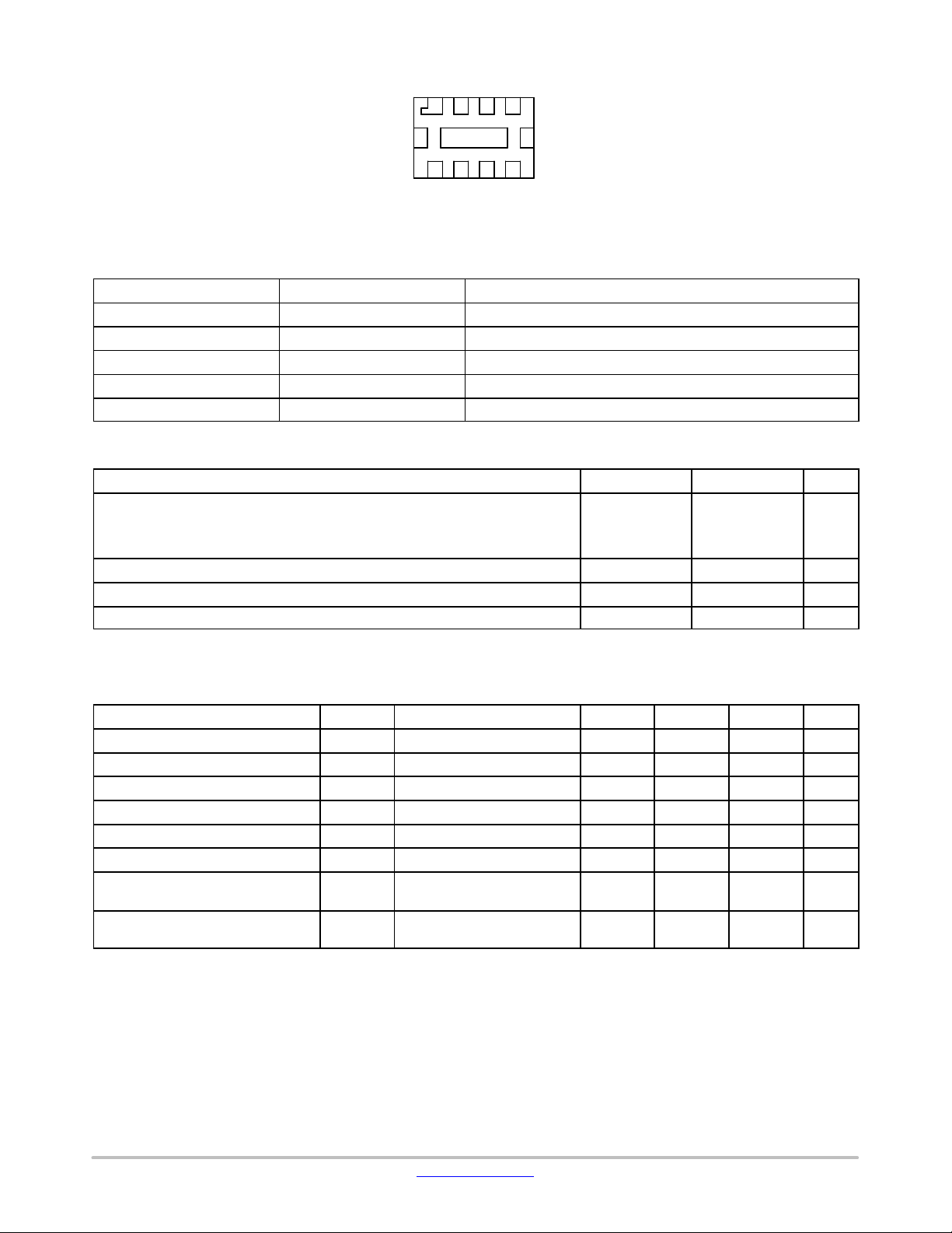
(Bottom View)
Figure 3. Pin Diagram
Table 1. FUNCTIONAL PIN DESCRIPTION
Filter Device Pins Description
Filter 1 1 & 8 Filter + ESD Channel 1
Filter 2 2 & 7 Filter + ESD Channel 2
Filter 3 3 & 6 Filter + ESD Channel 3
Filter 4 4 & 5 Filter + ESD Channel 4
Ground Pad GND Ground
MAXIMUM RATINGS
Parameter Symbol Value Unit
ESD Discharge IEC61000−4−2
Contact Discharge
Machine Model
Human Body Model
Operating Temperature Range T
Storage Temperature Range T
Maximum Lead Temperature for Soldering Purposes (1.8 in from case for 10 seconds) T
Stresses exceeding those listed in the Maximum Ratings table may damage the device. If any of these limits are exceeded, device functionality
should not be assumed, damage may occur and reliability may be affected.
V
PP
OP
STG
L
14
kV
1.6
16
−40 to 85 °C
−55 to 150 °C
260 °C
ELECTRICAL CHARACTERISTICS (T
Parameter
Maximum Reverse Working Voltage V
Breakdown Voltage V
Leakage Current I
Resistance R
Diode Capacitance C
Line Capacitance C
3 dB Cut−Off Frequency (Note 1) f
6 dB Cut−Off Frequency (Note 1) f
= 25°C unless otherwise noted)
J
Symbol Test Conditions Min Typ Max Unit
RWM
BR
R
A
d
L
3dB
6dB
IR = 1.0 mA 6.0 7.0 8.0 V
V
= 3.3 V 100 nA
RWM
IR = 10 mA 85 100 115
VR = 2.5 V, f = 1.0 MHz 10 13 16 pF
VR = 2.5 V, f = 1.0 MHz 20 26 32 pF
Above this frequency,
150 MHz
appreciable attenuation occurs
Above this frequency,
260 MHz
appreciable attenuation occurs
5.0 V
Product parametric performance is indicated in the Electrical Characteristics for the listed test conditions, unless otherwise noted. Product
performance may not be indicated by the Electrical Characteristics if operated under different conditions.
1. 50 source and 50 load termination.
www.onsemi.com
2
Page 3

NUF4001MU
0
S21 (dB)
NORMALIZED CAPACITANCE
0
9
TYPICAL PERFORMANCE CURVES
(TA= 25°C unless otherwise specified)
−5
−10
−15
−20
−25
−30
−35
−40
−45
−50
1.0E+6 10.0E+6 100E+6 1.0E+9 10.0E+9
FREQUENCY (Hz)
Figure 4. Insertion Loss Characteristic
2.0
1.5
1.0
0.5
0
0 1.0 2.0 3.0 4.0 5.0
REVERSE VOLTAGE (V)
Figure 6. Typical Capacitance vs.
Reverse Biased Voltage
(Normalized Capacitance Cd at 2.5 V)
−10
−20
−30
S41 (dB)
−40
−50
−60
10.0E+6 100E+6 1.0E+9 10.0E+
FREQUENCY (Hz)
Figure 5. Insertion Loss Characteristic
110
108
106
104
102
100
98
96
RESISTANCE ()
94
92
90
−40 −20 0 20 40 60 80
TEMPERATURE (°C)
Figure 7. Typical Resistance over Temperature
www.onsemi.com
3
Page 4

NUF4001MU
x
)
Theory of Operation
The NUF4001MU combines ESD protection and EMI
filtering conveniently into a small package for today’s size
constrained applications. The capacitance inherent to a
typical protection diode is utilized to provide the
capacitance value necessary to create the desired frequency
response based upon the series resistance in the filter. By
combining this functionality into one device, a large number
of discrete components are integrated into one small
package saving valuable board space and reducing BOM
count and cost in the application.
Application Example
The accepted practice for specifying bandwidth in a filter
is to use the 3 dB cutoff frequency. Utilizing points such as
the 6 dB or 9 dB cutoff frequencies results in signal
degradation in an application. This can be illustrated in an
application example. A typical application would include
EMI filtering of data lines in a camera or display interface.
In such an example it is important to first understand the
signal and its spectral content. By understanding these
things, an appropriate filter can be selected for the desired
application. A typical data signal is pattern of 1’s and 0’s
transmitted over a line in a form similar to a square wave.
The maximum frequency of such a signal would be the
pattern 1-0-1-0 such that for a signal with a data rate of
100 Mbps, the maximum frequency component would be
50 MHz. The next item to consider is the spectral content of
the signal, which can be understood with the Fourier series
approximation of a square wave, shown below in Equations
1 and 2 in the Fourier series approximation.
From this it can be seen that a square wave consists of odd
order harmonics and to fully construct a square wave n must
go to infinity. However , to retain an acceptable portion of the
waveform, the first two terms are generally sufficient. These
two terms contain about 85% of the signal amplitude and
allow a reasonable square wave to be reconstructed.
Therefore, to reasonably pass a square wave of frequency x
the minimum filter bandwidth necessary is 3x. All ON
Semiconductor EMI filters are rated according to this
principle. Attempting to violate this principle will result in
significant rounding of the waveform and cause problems in
transmitting the correct data. For example, take the filter
with the response shown in Figure 8 and apply three
different data waveforms. To calculate these three different
frequencies, the 3 dB, 6 dB, and 9 dB bandwidths will be
used.
Equation 1:
2
)
sin(0t)
ƪ
a
n + 1
1
)
1
ƪ
2n * 1
sin(3
sin((2n * 1)0t)
t)
sin(5
0
)
3
ƫ
(eq. 1)
t)
0
ƫ
) AAA
5
(eq. 2
1
x(t) +
2
Equation 2 (simplified form of Equation 1):
1
(t) +
2
)
2
Magnitude (dB)
100k 1M 100M 1G 10G
10M
Figure 8. Filter Bandwidth
From the above paragraphs it is shown that the maximum
supported frequency of a waveform that can be passed
through the filter can be found by dividing the bandwidth by
a factor of three (to obtain the corresponding data rate
multiply the result by two). The following table gives the
bandwidth values and the corresponding maximum
supported frequencies and the third harmonic frequencies.
f
1
f
Frequency (Hz)
Table 2. Frequency Chart
Bandwidth Maximum Supported
3 dB–100 MHz 33.33 MHz (f1) 100 MHz
6 dB–200 MHz 66.67 MHz (f2) 200 MHz
9 dB–300 MHz 100 MHz (f3) 300 MHz
−3 dB
−6 dB
−9 dB
2
f
3
Frequency
Third Harmonic
Frequency
www.onsemi.com
4
Page 5

NUF4001MU
Considering that 85% of the amplitude of the square is in
the first two terms of the Fourier series approximation most
of the signal content is at the fundamental (maximum
supported) frequency and the third harmonic frequency. I f a
signal with a frequency of 33.33 MHz is input to this filter,
the first two terms are sufficiently passed such that the signal
is only mildly affected, as is shown in Figure 9a. If a signal
with a frequency of 66.67 MHz is input to this same filter,
the third harmonic term is significantly attenuated. This
serves to round the signal edges and skew the waveform, as
is shown in Figure 9b. In the case that a 100 MHz signal is
input to this filter , the third harmonic term is attenuated even
Input Waveform Output Waveform
a) Frequency = f
further and results in even more rounding of the signal edges
as is shown in Figure 9c. The result is the degradation of the
data being transmitted making the digital data (1’s and 0’s)
more difficult to discern. This does not include effects of
other components such as interconnect and other path losses
which could further serve to degrade the signal integrity.
While some filter products may specify the 6 dB or 9 dB
bandwidths, actually using these to calculate supported
frequencies (and corresponding data rates) results in
significant signal degradation. To ensure the best signal
integrity possible, it is best to use the 3 dB bandwidth to
calculate the achievable data rate.
1
Input Waveform Output Waveform
b) Frequency = f
Input Waveform Output Waveform
c) Frequency = f
Figure 9. Input and Output Waveforms of Filter
2
3
Bluetooth is a registered trademark of Bluetooth SIG.
www.onsemi.com
5
Page 6

MECHANICAL CASE OUTLINE
PACKAGE DIMENSIONS
8
1
SCALE 4:1
2X
0.10 C
PIN ONE
REFERENCE
2X
0.05 C
8X
0.05 C
NOTE 4
8X
7X
PACKAGE
OUTLINE
D
A
B
E
0.10 C
TOP VIEW
DETAIL B
A
A1
SIDE VIEW
DETAIL A
L
K8X
D2
1
8
J
E2
8X
e
e/2
BOTTOM VIEW
SOLDERING FOOTPRINT*
1.10
0.25
(A3)
SEATING
C
PLANE
b
0.10 B
0.05ACC
0.45
UDFN8 1.8x1.2, 0.4P
CASE 517AD
EXPOSED Cu
A1
(0.10)
L1
NOTE 3
8X
ISSUE D
MOLD CMPD
A3
DETAIL B
ALTERNATE
CONSTRUCTIONS
0.05 MIN
DETAIL A
DETAIL A
OPTIONAL
CONSTRUCTION
NOTES:
1. DIMENSIONING AND TOLERANCING PER
ASME Y14.5M, 1994.
2. CONTROLLING DIMENSION: MILLIMETERS.
3. DIMENSION b APPLIES TO PLATED TERMINAL
AND IS MEASURED BETWEEN 0.15 AND
0.30 mm FROM TERMINAL.
4. COPLANARITY APPLIES TO THE EXPOSED
PAD AS WELL AS THE TERMINALS.
MILLIMETERS
DIM MIN MAX
A 0.45 0.55
A1 0.00 0.05
A3 0.13 REF
b 0.15 0.25
D 1.80 BSC
E 1.20 BSC
e 0.40 BSC
D2 0.90 1.10
E2 0.20 0.30
J 0.19 REF
K 0.20 TYP
L
L 0.20 0.30
L1 −−− 0.10
GENERIC
MARKING DIAGRAM*
XXM
G
1
XX = Specific Device Code
M = Date Code
G = Pb−Free Package
*This information is generic. Please refer
to device data sheet for actual part
marking. Pb−Free indicator, “G”, may
or not be present.
DATE 23 OCT 2012
1.50
0.35
1
0.35
DIMENSIONS: MILLIMETERS
0.40 PITCH
*For additional information on our Pb−Free strategy and soldering
details, please download the ON Semiconductor Soldering and
Mounting Techniques Reference Manual, SOLDERRM/D.
DOCUMENT NUMBER:
DESCRIPTION:
ON Semiconductor and are trademarks of Semiconductor Components Industries, LLC dba ON Semiconductor or its subsidiaries in the United States and/or other countries.
ON Semiconductor reserves the right to make changes without further notice to any products herein. ON Semiconductor makes no warranty, representation or guarantee regarding
the suitability of its products for any particular purpose, nor does ON Semiconductor assume any liability arising out of the application or use of any product or circuit, and specifically
disclaims any and all liability, including without limitation special, consequential or incidental damages. ON Semiconductor does not convey any license under its patent rights nor the
rights of others.
© Semiconductor Components Industries, LLC, 2019
98AON22154D
UDFN8 1.8X1.2, 0.4P
Electronic versions are uncontrolled except when accessed directly from the Document Repository.
Printed versions are uncontrolled except when stamped “CONTROLLED COPY” in red.
PAGE 1 OF 1
www.onsemi.com
Page 7

ON Semiconductor and are trademarks of Semiconductor Components Industries, LLC dba ON Semiconductor or its subsidiaries in the United States and/or other countries.
ON Semiconductor owns the rights to a number of patents, trademarks, copyrights, trade secrets, and other intellectual property. A listing of ON Semiconductor ’s product/patent
coverage may be accessed at www.onsemi.com/site/pdf/Patent−Marking.pdf
ON Semiconductor makes no warranty, representation or guarantee regarding the suitability of its products for any particular purpose, nor does ON Semiconductor assume any liability
arising out of the application or use of any product or circuit, and specifically disclaims any and all liability, including without limitation special, consequential or incidental damages.
Buyer is responsible for its products and applications using ON Semiconductor products, including compliance with all laws, regulations and safety requirements or standards,
regardless of any support or applications information provided by ON Semiconductor. “Typical” parameters which may be provided in ON Semiconductor data sheets and/or
specifications can and do vary in different applications and actual performance may vary over time. All operating parameters, including “Typicals” must be validated for each customer
application by customer’s technical experts. ON Semiconductor does not convey any license under its patent rights nor the rights of others. ON Semiconductor products are not
designed, intended, or authorized for use as a critical component in life support systems or any FDA Class 3 medical devices or medical devices with a same or similar classification
in a foreign jurisdiction or any devices intended for implantation in the human body. Should Buyer purchase or use ON Semiconductor products for any such unintended or unauthorized
application, Buyer shall indemnify and hold ON Semiconductor and its officers, employees, subsidiaries, affiliates, and distributors harmless against all claims, costs, damages, and
expenses, and reasonable attorney fees arising out of, directly or indirectly, any claim of personal injury or death associated with such unintended or unauthorized use, even if such
claim alleges that ON Semiconductor was negligent regarding the design or manufacture of the part. ON Semiconductor is an Equal Opportunity/Affirmative Action Employer. This
literature is subject to all applicable copyright laws and is not for resale in any manner.
. ON Semiconductor reserves the right to make changes without further notice to any products herein.
PUBLICATION ORDERING INFORMATION
LITERATURE FULFILLMENT:
Email Requests to: orderlit@onsemi.com
ON Semiconductor Website: www.onsemi.com
TECHNICAL SUPPORT
North American Technical Support:
Voice Mail: 1 800−282−9855 Toll Free USA/Canada
Phone: 011 421 33 790 2910
Europe, Middle East and Africa Technical Support:
Phone: 00421 33 790 2910
For additional information, please contact your local Sales Representative
◊
www.onsemi.com
1
 Loading...