

Page 1
Voltage-Level Translator,
2
Dual Bidirectional I
C-bus
and SMBus
NLA9306
The NLA9306 is a dual bidirectional I2C−bus and SMBus
voltage−level translator with an enable (EN) input.
www.onsemi.com
Features
• 2−bit Bidirectional Translator for SDA and SCL Lines in
2
Mixed−Mode I
• Standard−Mode, Fast−Mode, and Fast−Mode Plus I
C−Bus Applications
2
C−Bus and
SMBus Compatible
• Less Than 1.5 ns Maximum Propagation Delay to Accommodate
2
Standard−Mode and Fast−Mode I
C−Bus Devices and Multiple
Masters
• Allows Voltage Level Translation Between:
♦ 1.0 V V
1.2 V V
♦
♦
1.8 V V
2.5 V V
♦
3.3 V V
♦
and 1.8 V, 2.5 V, 3.3 V or 5 V V
ref(1)
and 1.8 V, 2.5 V, 3.3 V or 5 V V
ref(1)
and 3.3 V or 5 V V
ref(1)
ref(1)
ref(1)
and 5 V V
and 5 V V
bias(ref)(2)
bias(ref)(2)
bias(ref)(2)
bias(ref)(2)
bias(ref)(2)
• Provides Bidirectional Voltage Translation With No Direction Pin
• Low 3.5 W ON−State Connection Between Input and Output Ports
Provides Less Signal Distortion
• Open−Drain I
• 5 V Tolerant I
2
C−Bus I/O Ports (SCL1, SDA1, SCL2 and SDA2)
2
C−Bus I/O Ports to Support Mixed−Mode Signal
Operation
• High−Impedance SCL1, SDA1, SCL2 and SDA2 Pins for
EN = LOW
• Lock−Up Free Operation
• Flow Through Pinout for Ease of Printed−Circuit Board Trace
Routing
• Packages Offered:
♦ US8, UQFN8, UDFN8
• ESD Performance: 2000 V Human Body Model
• NLV Prefix for Automotive and Other Applications Requiring
Unique Site and Control Change Requirements; AEC−Q100
Qualified and PPAP Capable
• These Devices are Pb−Free, Halogen Free/BFR Free and are RoHS
Compliant
MARKING
DIAGRAMS
8
US8
US SUFFIX
CASE 493
UQFN8
8
1
XXXX = Specific Device Code
A = Assembly Location
L = Lot Code
Y = Year
W = Work Week
M = Date Code
G = Pb−Free Package
ORDERING INFORMATION
See detailed ordering and shipping information in the package
dimensions section on page 9 of this data sheet.
MU SUFFIX
CASE 523AN
UDFN8
1.45 x 1.0
CASE 517BZ
XXXX
ALYW
1
1
XX MG
X M
1
© Semiconductor Components Industries, LLC, 2018
March, 2021 − Rev. 2
1 Publication Order Number:
NLA9306/D
Page 2
NLA9306
Function Description
The NLA9306 is a dual bidirectional I2C−bus and SMBus
voltage−level translator with an enable (EN) input, and is
operational from 1.0 V to 3.6 V (V
(V
bias(ref)(2)
).
) and 1.8 V to 5.5 V
ref(1)
The NLA9306 allows bidirectional voltage translations
between 1.0 V and 5 V without the use of a direction pin. The
low ON−state resistance (R
) of the switch allows
on
connections to be made with minimal propagation delay.
When EN is HIGH, the translator switch is on, and the SCL1
and SDA1 I/O are connected to the SCL2 and SDA2 I/O,
respectively, allowing bidirectional data flow between
ports. When EN is LOW, the translator switch is off, and a
high−impedance state exists between ports.
The NLA9306 is not a bus buffer that provides both level
translation and physical capacitance isolation to either side
of the bus when both sides are connected. The NLA9306
only isolates both sides when the device is disabled and
provides voltage level translation when active.
The NLA9306 can be used to run two buses, one at
400 kHz operating frequency and the other at 100 kHz
operating frequency. If the two buses are operating at
different frequencies, the 100 kHz bus must be isolated
when the 400 kHz operation of the other bus is required. If
the master is running at 400 kHz, the maximum system
operating frequency may be less than 400 kHz because of
the delays added by the translator.
As with the standard I
2
C−bus system, pull−up resistors are
required to provide the logic HIGH levels on the translator’s
bus. The NLA9306 has a standard open−collector
configuration of the I
2
C−bus. The size of these pull−up
resistors depends on the system, but each side of the
translator must have a pull−up resistor. The device is
designed to work with Standard−mode, Fast−mode and Fast
mode Plus I
2
C−bus devices in addition to SMBus devices.
The maximum frequency is dependent on the RC time
constant, but generally supports > 2 MHz.
When the SDA1 or SDA2 port is LOW, the clamp is in the
ON−state and a low resistance connection exists between the
SDA1 and SDA2 ports. Assuming the higher voltage is on
the SDA2 port, when the SDA2 port is HIGH, the voltage on
the SDA1 port is limited to the voltage set by VREF1. When
the SDA1 port is HIGH, the SDA2 port is pulled to the drain
pull−up supply voltage (V
) by the pull−up resistors.
pu(D)
This functionality allows a seamless translation between
higher and lower voltages selected by the user without the
need for directional control. The SCL1/SCL2 channel also
functions as the SDA1/SDA2 channel.
All channels have the same electrical characteristics and
there is minimal deviation from one output to another in
voltage or propagation delay. This is a benefit over discrete
transistor voltage translation solutions, since the fabrication
of the switch is symmetrical. The translator provides
excellent ESD protection to lower voltage devices, and at the
same time protects less ESD−resistant devices.
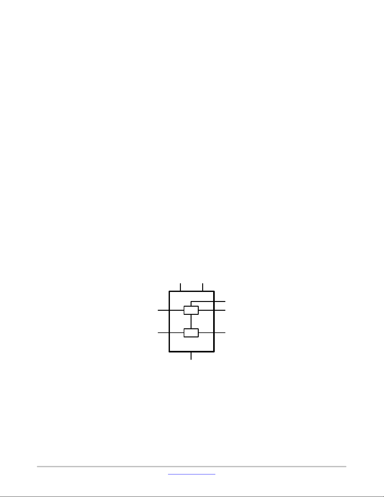
FUNCTIONAL DIAGRAM
VREF1
SCL1
3
4
Figure 1. Logic Diagram
VREF2
2
NLA9306
SW
SW
1
GND
7
8
EN
6
SCL2
5
SDA2SDA1
www.onsemi.com
2
Page 3
NLA9306
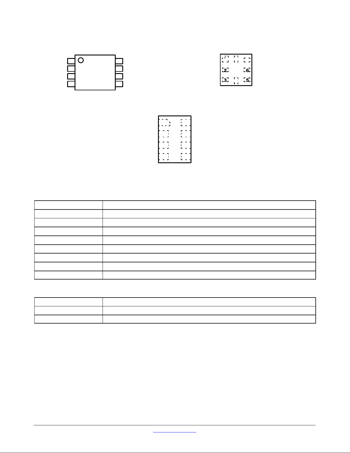
PIN ASSIGNMENTS
EN
GND
VREF1
SCL1
SDA1
1
2
3
4
NLA9306
8
7
6
5
EN
VREF2
SCL2
SDA2
GND
VREF1
SCL1
Figure 2. US8 Pinouts Figure 3. UQFN8 Pinout (Top Thru View)
8
1
NLA9306
2
3
4
SDA1
7
6
5
VREF2
SCL2
SDA2
Table 1. PIN DESCRIPTION
Pin Description
GND Ground
VREF1 Low−voltage side reference supply voltage for SCL1 and SDA1
SCL1 Serial clock, low−voltage side; connect to VREF1 through a pull−up resistor
SDA1 Serial data, low−voltage side; connect to VREF1 through a pull−up resistor
SDA2 Serial data, high−voltage side; connect to VREF2 through a pull−up resistor
SCL2 Serial clock, high−voltage side; connect to VREF2 through a pull−up resistor
VREF2 High−voltage side reference supply voltage for SCL2 and SDA2
EN Switch enable input; connect to VREF2 and pull−up through a high resistor
GND
VREF1
SCL1
1
2
3
4
8
7
6
5
EN
VREF2
SCL2
SDA2SDA1
Figure 4. UDFN8 Pinout (Top Thru View)
Table 2. FUNCTION TABLE
Input EN (Note 1) Function
Low Disconnect
High SCL1 = SCL2; SDA1 = SDA2
1. EN is controlled by the V
bias(ref)(2)
logic levels and should be at least 1 V higher than V
www.onsemi.com
3
for best translator operation.
ref(1)
Page 4
NLA9306
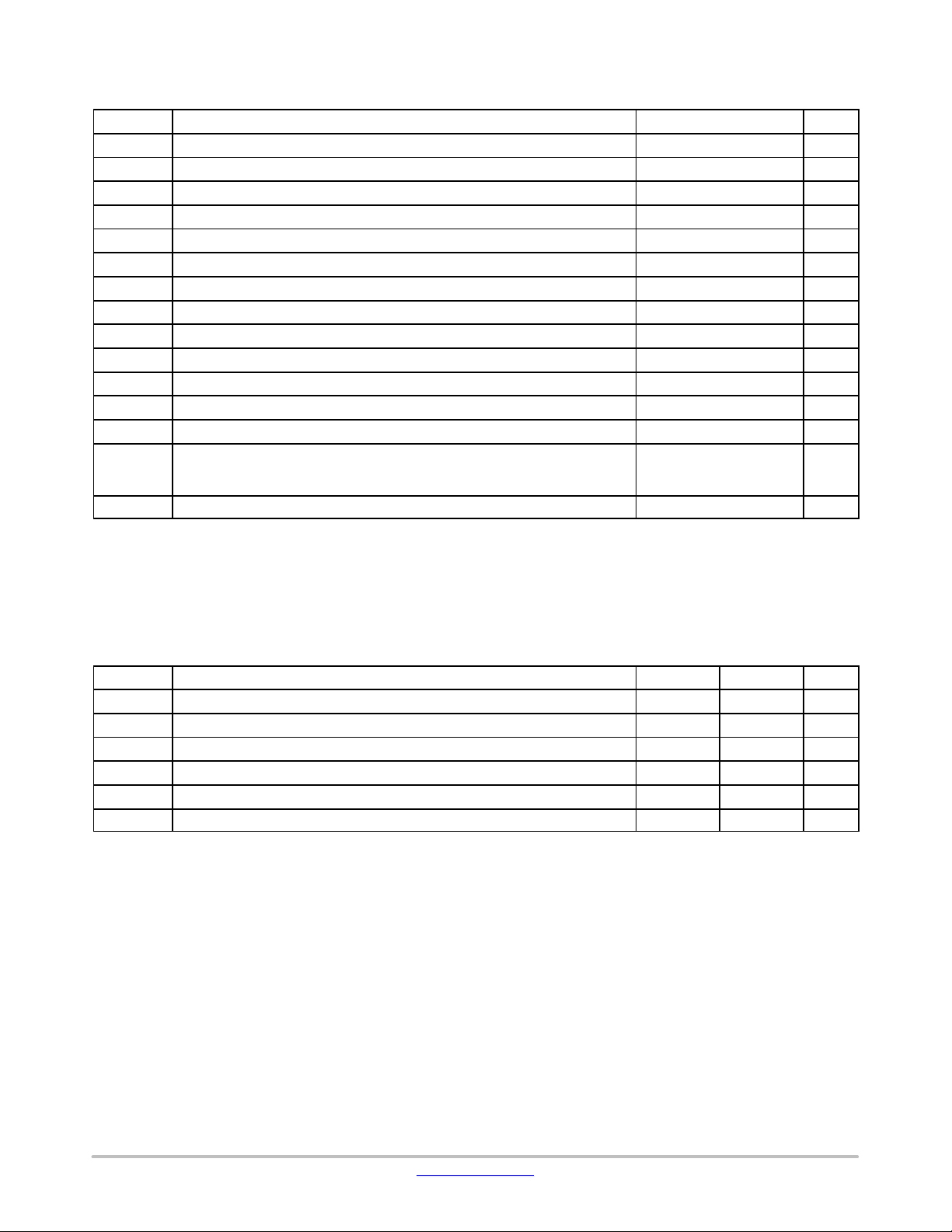
Table 3. MAXIMUM RATINGS
Symbol Parameter Value Unit
V
ref(1)
V
bias(ref)(2)
V
IN
V
I/O
I
CH
I
IK
T
STG
T
L
T
J
q
JA
P
D
MSL Moisture Sensitivity Level 1
F
R
V
ESD
I
LATCHUP
Stresses exceeding those listed in the Maximum Ratings table may damage the device. If any of these limits are exceeded, device functionality
should not be assumed, damage may occur and reliability may be affected.
2. Measured with minimum pad spacing on an FR4 board, using 10 mm−by−1 inch, 2 ounce copper trace no air flow.
3. Tested to ANSI / ESDA / JEDEC JS−001−2017.
4. JEDEC recommends that ESD qualification to EIA / JESD22−A115−A (Machine Model) be discontinued per JEDEC / JEP172A.
5. Tested to EIA / JESD22−C101−F.
6. Tested to EIA / JESD78 Class II.
Reference Voltage (Note 2) −0.5 to +7.0 V
Reference Bias Voltage (Note 3) −0.5 to +7.0 V
Input Voltage −0.5 to +7.0 V
Input / Output Pin Voltage −0.5 to +7.0 V
DC Channel Current 128 mA
DC Input Diode Current VIN < GND −50 mA
Storage Temperature Range −65 to +150 °C
Lead Temperature, 1 mm from Case for 10 Seconds TL = 260 °C
Junction Temperature Under Bias TJ = 150 °C
Thermal Resistance (Note 2)
qJA = 150
°C/W
Power Dissipation in Still Air at 85°C PD = 833 mW
Flammability Rating Oxygen Index: 28 to 34 UL 94 V−0 @ 0.125 in
ESD Withstand Voltage Human Body Mode (Note 3)
Machine Model (Note 4)
Charged Device Model (Note 5)
> 2000
N/A
> 1000
V
Latchup Performance Above VCC and Below GND at 125°C (Note 6) ±100 mA
Table 4. RECOMMENDED OPERATING CONDITIONS
Symbol Parameter Min Max Unit
V
ref(1)
V
bias(ref)(2)
V
I/O
V
I(EN)
I
sw(pass)
T
Functional operation above the stresses listed in the Recommended Operating Ranges is not implied. Extended exposure to stresses beyond
the Recommended Operating Ranges limits may affect device reliability.
7. V
(ref)(1)
Reference Voltage (1) (Note 7) VREF1 0 5.5 V
Reference Bias Voltage (2) (Note 7) VREF2 0 5.5 V
Input / Output Pin Voltage SCL1, SDA1, SCL2, SDA2 0 5.5 V
Control Pin Input Voltage EN 0 5.5 V
Pass Switch Current 0 64 mA
Operating Free−Air Temperature −55 +125 °C
A
≤ V
bias(ref)(2)
−1 V for best results in level shifting applications.
www.onsemi.com
4
Page 5

NLA9306
Table 5. DC ELECTRICAL CHARACTERISTICS
Symbol Parameter Conditions
C
C
V
IK
I
IH
i(EN)
i/O(off)
Input Clamping Voltage I
High−Level Input Current V
EN Pin Input Capacitance V
OFF−State I/O Pin Capacitance
SCLn, SDAn
= −18 mA; V
I
= 5 V; V
I
= 3 V or 0 V 7.1 pF
I
V
= 3 V or 0 V; V
O
I(EN)
= 0 V 5
I(EN)
TA = −555C to +1255C
Typ
Min
= 0 V −1.2 V
= 0 V 4 6 pF
I(EN)
(Note 8)
Max
Unit
mA
C
R
i/O(on)
ON
ON−State I/O Pin Capacitance
SCLn, SDAn
ON−State Resistance
(2)(3)
SCLn, SDAn VI = 0 V; IO = 64 mA
V
= 3 V or 0 V;
O
V
= 3 V 9.3 13.1
I(EN)
V
= 4.5 V
I(EN)
V
= 3 V
I(EN)
= 2.3 V
V
I(EN)
V
= 1.5 V
I(EN)
V
= 2.4 V; IO = 15 mA
I
V
= 4.5 V
I(EN)
= 3 V
V
I(EN)
V
= 1.7 V; IO = 15 mA
I
V
= 2.3 V 40 80
I(EN)
2.4
3.0
3.8
9.0
4.8
46
pF
W
5.0
6.0
8.0
20
7.5
80
Product parametric performance is indicated in the Electrical Characteristics for the listed test conditions, unless otherwise noted. Product
performance may not be indicated by the Electrical Characteristics if operated under different conditions.
8. All typical values are at T
9. Measured by the voltage drop between the SCL1 and SCL2, or SDA1 and SDA2 terminals at the indicated current through the switch.
= 25°C.
A
ON−state resistance is determined by the lowest voltage of the two terminals.
10.Guaranteed by design.
Table 6. AC ELECTRICAL CHARACTERISTICS (Translating Down) − Values Guaranteed by Design
TA = −555C to +1255C
Min Max
Unit
ns
ns
Symbol
Parameter Test Condition
SEE FIGURE 4 LOAD SWITCH AT S2 POSITION
t
PLH
Low−to−High Propagation Delay, from (input) SCL2 or
SDA2 to (output) SCL1 or
SDA1
t
PHL
High−to−Low Propagation Delay, from (input) SCL2 or
SDA2 to (output) SCL1 or
SDA1
t
PLH
Low−to−High Propagation Delay, from (input) SCL2 or
SDA2 to (output) SCL1 or
SDA1
t
PHL
High−to−Low Propagation Delay, from (input) SCL2 or
SDA2 to (output) SCL1 or
SDA1
V
= 3.3 V; V
I(EN)
VIL = 0 V; V
V
I(EN)
V
= 0 V; VM = 0.75 V
IL
= 1.15 V
M
= 2.5 V; VIH = 2.5 V;
= 3.3 V;
IH
Load
Condition
CL = 15 pF 0 0.6
CL = 30 pF 0 1.2
CL = 50 pF 0 2.0
CL = 15 pF 0 0.75
CL = 30 pF 0 1.5
CL = 50 pF 0 2.0
CL = 15 pF 0 0.6
CL = 30 pF 0 1.2
CL = 50 pF 0 2.0
CL = 15 pF 0 0.75
CL = 30 pF 0 1.5
CL = 50 pF 0 2.5
www.onsemi.com
5
Page 6

NLA9306
Table 7. AC ELECTRICAL CHARACTERISTICS (Translating Up) − Values Guaranteed by Design
Symbol
SEE FIGURE 4 LOAD SWITCH AT S1 POSITION
t
PLH
Low−to−High Propagation Delay, from (input) SCL1 or
SDA1 to (output) SCL2 or
SDA2
t
PHL
High−to−Low Propagation Delay, from (input) SCL1 or
SDA1 to (output) SCL2 or
SDA2
t
PLH
Low−to−High Propagation Delay, from (input) SCL1 or
SDA1 to (output) SCL2 or
SDA2
t
PHL
High−to−Low Propagation Delay, from (input) SCL1 or
SDA1 to (output) SCL2 or
SDA2
Parameter Test Condition Load Condition
V
I(EN)
V
= 0 V; V
IL
V
= 1.15 V
M
= 3.3 V; V
= 3.3 V;
TT
= 2.3 V;
IH
RL = 300 W, CL = 15 pF
RL = 300 W, CL = 30 pF
RL = 300 W, CL = 50 pF
RL = 300 W, CL = 15 pF
RL = 300 W, CL = 30 pF
RL = 300 W, CL = 50 pF
V
= 2.5 V; VIH = 1.5 V;
I(EN)
V
= 0 V; V
IL
= 0.75 V
V
M
TT
= 2.5 V;
RL = 300 W, CL = 15 pF
RL = 300 W, CL = 30 pF
RL = 300 W, CL = 50 pF
RL = 300 W, CL = 15 pF
RL = 300 W, CL = 30 pF
RL = 300 W, CL = 50 pF
TA =
−555C to +1255C
Min Max
0 0.5
0 1.0
0 1.75
0 0.8
0 1.65
0 2.75
0 0.5
0 1.0
0 1.75
0 1.0
0 2.0
0 3.3
Unit
ns
ns
V
from output under test
TT
R
L
S1
S2 (open)
C
L
input
output
V
M
V
M
A. Load Circuit B. Timing Diagram
S1 = translating up; S2 = translating down.
includes probe and jig capacitance.
C
L
All input pulses are supplied by generators having the following characteristics: PRR ≤ 10 MHz; Z
The outputs are measured one at a time, with one transition per measurement.
Figure 5. Load Circuit for Outputs
V
V
= 50 W; t
o
M
M
≤ 2 ns; t
r
V
IH
V
IL
V
OH
V
OL
≤ 2 ns.
f
www.onsemi.com
6
Page 7

V
CC
2
C−Bus
I
MASTER
SCL
SDA
V
REF(1)
= 1.8 V
(Note 1)
R
PURPU
NLA9306
APPLICATION INFORMATION
200 kW
VREF1
SCL1
SDA1
2
3
4
NLA9306
SW
SW
EN
8
VREF2
7
65SCL2
SDA2
V
PU(D)
= 3.3 V
(Note 1)
R
PURPU
SCL
I2C−Bus
DEVICE
SDA
V
CC
GND
1. The applied voltages at V
operation.
V
CC
2
C−Bus
I
MASTER
GND
ref(1)
and V
should be such that V
pu(D)
Figure 6. Typical Application (Switch Always Enabled)
3.3 V Enable Signal (Note 2)
V
= 1.8 V
REF(1)
(Note 2)
SCL
SDA
RPUR
VREF1
PU
SCL1
SDA1
2
3
4
1
GND
bias(ref)(2)
ONOFF
NLA9306
SW
SW
1
GND
is at least 1 V higher than V
200 kW
EN
8
VREF2
7
65SCL2
SDA2
2. In the Enabled mode, the applied enable voltage and the applied voltage at V
higher than V
for best translator operation.
ref(1)
Figure 7. Typical Application (Switch Enable Control)
V
= 3.3 V
PU(D)
R
PURPU
should be such that V
ref(1)
SCL
2
I
DEVICE
SDA
GND
for best translator
ref(1)
V
CC
C−Bus
GND
bias(ref)(2)
is at least 1 V
Bidirectional Translation
For the bidirectional clamping configuration (higher
voltage to lower voltage or lower voltage to higher voltage),
the EN input must be connected to VREF2 and both pins
pulled to HIGH side V
through a pull−up resistor
pu(D)
(typically 200 kW). This allows VREF2 to regulate the EN
input. A filter capacitor on VREF2 is recommended. The
2
I
C−bus master output can be totem−pole or open−drain
(pull−up resistors may be required) and the I
2
C−bus device
output can be totem−pole or open−drain (pull−up resistors
are required to pull the SCL2 and SDA2 outputs to V
pu(D)).
However, if either output is totem−pole, data must be
www.onsemi.com
unidirectional or the outputs must be 3−stateable and be
controlled by some direction−control mechanism to prevent
HIGH−to−LOW contentions in either direction. If both
outputs are open−drain, no direction control is needed.
The reference supply voltage (V
) is connected to the
ref(1)
processor core power supply voltage. When VREF2 is
connected through a 200 kW resistor to a 3.3 V to 5.5 V
power supply, and V
V
pu(D)
(V
− 1 V), the output of each SCL1 and SDA1 has a
pu(D)
is set between 1.0 V and
ref(1)
maximum output voltage equal to VREF1, and the output of
each SCL2 and SDA2 has a maximum output voltage equal
to V
7
pu(D)
.
Page 8

NLA9306
Table 8. APPLICATION OPERATING CONDITIONS Refer to Figure 6.
Symbol
V
bias(ref)(2)
V
I(EN)
V
ref(1)
I
sw(pass)
I
ref
T
amb
11.All typical values are at T
Sizing Pull−up Resistor
The pull−up resistor value needs to limit the current
through the pass transistor when it is in the ON state to about
15 mA. This ensures a pass voltage of 260 mV to 350 mV.
If the current through the pass transistor is higher than
15 mA, the pass voltage also is higher in the ON state. To set
the current through each pass transistor at 15 mA, the
pull−up resistor value is calculated as:
Parameter Conditions Min Typ
Reference Bias Voltage (2) V
EN Pin Input Voltage V
Reference Voltage (1) 0 1.5 4.4 V
Pass Switch Current 14 mA
Reference Current Transistor 5
Ambient Temperature Operating in free−air −55 +125 °C
= 25 °C.
amb
voltages and currents at 15 mA, 10 mA, and 3 mA. The
resistor values shown in the +10% column or a larger value
should be used to ensure that the pass voltage of the
transistor would be 350 mV or less. The external driver must
be able to sink the total current from the resistors on both
sides of the NLA9306 device at 0.175 V, although the
15 mA only applies to current flowing through the
NLA9306 device.
RPU+
V
PU(D)
0.015 A
* 0.35 V
(eq. 1)
(1)
+ 0.6 2.1 5 V
ref(1)
+ 0.6 2.1 5 V
ref(1)
Max Unit
mA
The following table summarizes resistor reference
Table 9. PULLUP RESISTOR VALUES Calculated for V
15 mA 10 mA 3 mA
V
pu(D)
5 V 310 341 465 512 1550 1705
3.3 V 197 217 295 325 983 1082
2.5 V 143 158 215 237 717 788
1.8 V 97 106 145 160 483 532
1.5 V 77 85 11 5 127 383 422
1.2 V 57 63 85 94 283 312
12.+10% to compensate for V
Nominal +10% (Note 12) Nominal +10%
range and resistor tolerance.
CC
Maximum Frequency Calculation
The maximum frequency is totally dependent upon the
specifics of the application and the device can operate >
33 MHz. Basically, the NLA9306 behaves like a wire with
the additional characteristics of transistor device physics
and should be capable of performing at higher frequencies
if used correctly.
Here are some guidelines to follow that will help
maximize the performance of the device:
• Keep trace length to a minimum by placing the
NLA9306 close to the processor.
• The trace length should be less than half the time of
flight to reduce ringing and reflections.
• The faster the edge of the signal, the higher the chance
for ringing.
• The higher the drive strength (up to 15 mA), the higher
the frequency the device can use.
In a 3.3 V to 1.8 V direction level shift, if the 3.3 V side
= 0.35 V; assumes output driver VOL = 0.175 V at stated current.
OL
Pullup Resistor Value (W)
(1)
Nominal +10% (Note 12)
resistor is needed on the 3.3 V side. The capacitance and line
length of concern is on the 1.8 V side since it is driven
through the ON resistance of the NLA9306. If the line length
on the 1.8 V side is long enough there can be a reflection at
the chip/terminating end of the wire when the transition time
is shorter than the time of flight of the wire because the
NLA9306 looks like a high−impedance compared to the
wire. If the wire is not too long and the lumped capacitance
is not excessive the signal will only be slightly degraded by
the series resistance added by passing through the
NLA9306. If the lumped capacitance is large the rise time
will deteriorate, the fall time is much less affected and if the
rise time is slowed down too much the duty cycle of the clock
will be degraded and at some point the clock will no longer
be useful. So the principle design consideration is to
minimize the wire length and the capacitance on the 1.8 V
side for the clock path. A pull−up resistor on the 1.8 V side
can also be used to trade a slower fall time for a faster rise
time and can also reduce the overshoot in some cases.
is being driven by a totem pole type driver no pull−up
www.onsemi.com
8
Page 9

NLA9306
ORDERING INFORMATION
Pin 1 Orientation
Device Marking
NLA9306MUQ1TCG AY Q4 UQFN8
NLA9306MU3TAG D Q1 UDFN8
NLA9306MU3TCG D Q4 UDFN8
NLA9306USG
NLVA9306USG*
†For information on tape and reel specifications, including part orientation and tape sizes, please refer to our Tape and Reel Packaging
Specifications Brochure, BRD8011/D.
*NLV Prefix for Automotive and Other Applications Requiring Unique Site and Control Change Requirements; AEC−Q100 Qualified and PPAP
Capable.
A5 Q4
A5 Q4
(See below)
Package Shipping
(Pb−Free)
(Pb−Free)
(Pb−Free)
US8
(Pb−Free)
US8
(Pb−Free)
3000 / Tape & Reel
3000 / Tape & Reel
3000 / Tape & Reel
3000 / Tape & Reel
3000 / Tape & Reel
Pin 1 Orientation in Tape and Reel
†
www.onsemi.com
9
Page 10

NLA9306
PACKAGE DIMENSIONS
US8
CASE 493
ISSUE D
SEATING
PLANE
T
A
X Y
58
J
DETAIL E
LB
41
P
G
C
D
K
0.10 (0.004) XY
M
T
R
S
U
H
T0.10 (0.004)
N
R 0.10 TYP
V
F
NOTES:
1. DIMENSIONING AND TOLERANCING PER ANSI
Y14.5M, 1982.
2. CONTROLLING DIMENSION: MILLIMETERS.
3. DIMENSION A DOES NOT INCLUDE MOLD
FLASH, PROTRUSION OR GATE BURR. MOLD
FLASH. PROTRUSION AND GATE BURR SHALL
NOT EXCEED 0.14MM (0.0055”) PER SIDE.
4. DIMENSION B DOES NOT INCLUDE INTERLEAD
FLASH OR PROTRUSION. INTERLEAD FLASH
AND PROTRUSION SHALL NOT EXCEED 0.14MM
(0.0055”) PER SIDE.
5. LEAD FINISH IS SOLDER PLATING WITH
THICKNESS OF 0.0076−0.0203MM (0.003−0.008”).
6. ALL TOLERANCE UNLESS OTHERWISE
SPECIFIED ±0.0508MM (0.0002”).
MILLIMETERS
DIMAMIN MAX MIN MAX
1.90 2.10 0.075 0.083
B 2.20 2.40 0.087 0.094
C 0.60 0.90 0.024 0.035
D 0.17 0.25 0.007 0.010
F 0.20 0.35 0.008 0.014
G 0.50 BSC 0.020 BSC
H 0.40 REF 0.016 REF
J 0.10 0.18 0.004 0.007
K 0.00 0.10 0.000 0.004
L 3.00 3.20 0.118 0.128
M 0 6 0 6
____
N 0 10 0 10
M
____
P 0.23 0.34 0.010 0.013
R 0.23 0.33 0.009 0.013
S 0.37 0.47 0.015 0.019
U 0.60 0.80 0.024 0.031
V 0.12 BSC
INCHES
0.005 BSC
DETAIL E
RECOMMENDED
SOLDERING FOOTPRINT*
8X
0.30
8X
0.68
3.40
1
0.50
PITCH
DIMENSIONS: MILLIMETERS
*For additional information on our Pb−Free strategy and soldering
details, please download the ON Semiconductor Soldering and
Mounting Techniques Reference Manual, SOLDERRM/D.
www.onsemi.com
10
Page 11

NLA9306
PACKAGE DIMENSIONS
UQFN8, 1.6x1.6, 0.5P
CASE 523AN
ISSUE O
PIN ONE
REFERENCE
2X
0.10 C
2X
0.05 C
0.05 C
DETAIL A
0.10 C
TOP VIEW
SIDE VIEW
8X
L
3
1
BOTTOM VIEW
D
DETAIL B
8
A1
8X
5
7
A
B
E
(A3)
L3
8X
A
C
e
b
0.10 B
0.05ACC
EXPOSED Cu
A1
SEATING
PLANE
NOTE 3
DETAIL B
OPTIONAL
CONSTRUCTION
L1
b
(0.10)
DETAIL A
OPTIONAL
CONSTRUCTION
*For additional information on our Pb−Free strategy and soldering
MOLD CMPD
A3
L3
NOTES:
1. DIMENSIONING AND TOLERANCING PER
ASME Y14.5M, 1994.
2. CONTROLLING DIMENSION: MILLIMETERS.
3. DIMENSION b APPLIES TO PLATED TERMINAL
AND IS MEASURED BETWEEN 0.15 AND
0.30 mm FROM THE TERMINAL TIP.
MILLIMETERS
DIM MIN MAX
A 0.45 0.60
A1 0.00 0.05
A3 0.13 REF
b 0.15 0.25
D 1.60 BSC
E 1.60 BSC
e 0.50 BSC
L 0.35 0.45
L1 −−− 0.15
L3 0.25 0.35
(0.15)
SOLDERING FOOTPRINT*
1.70
1
0.35
7X
0.25
DIMENSIONS: MILLIMETERS
details, please download the ON Semiconductor Soldering and
Mounting Techniques Reference Manual, SOLDERRM/D.
0.50
PITCH
1.70
8X
0.538X0.53
www.onsemi.com
11
Page 12

PIN ONE
REFERENCE
2X
2X
0.10 C
0.10
0.05 C
0.05 C
L1
C
e/2
D
TOP VIEW
SIDE VIEW
1
NLA9306
PACKAGE DIMENSIONS
UDFN8, 1.45x1, 0.35P
CASE 517BZ
ISSUE O
A B
E
A3
A
A1
e
4
SEATING
C
PLANE
L7X
NOTES:
1. DIMENSIONING AND TOLERANCING PER
ASME Y14.5M, 1994.
2. CONTROLLING DIMENSION: MILLIMETERS.
3. DIMENSION b APPLIES TO PLATED
TERMINAL AND IS MEASURED BETWEEN
0.15 AND 0.20 MM FROM TERMINAL TIP.
4. PACKAGE DIMENSIONS EXCLUSIVE OF
BURRS AND MOLD FLASH.
MILLIMETERS
DIM MIN MAX
A 0.45 0.55
A1 0.00 0.05
A3 0.13 REF
b 0.15 0.25
D 1.45 BSC
E 1.00 BSC
e 0.35 BSC
L 0.25 0.35
L1 0.30 0.40
RECOMMENDED
SOLDERING FOOTPRINT*
7X
0.48
8X
0.22
1.18
58
BOTTOM VIEW
b
8X
0.10 B
0.05ACC
PKG
OUTLINE
1
DIMENSIONS: MILLIMETERS
0.35
PITCH
M
M
NOTE 3
0.53
*For additional information on our Pb−Free strategy and soldering
details, please download the ON Semiconductor Soldering and
Mounting Techniques Reference Manual, SOLDERRM/D.
ON Semiconductor and are trademarks of Semiconductor Components Industries, LLC dba ON Semiconductor or its subsidiaries in the United States and/or other countries.
ON Semiconductor owns the rights to a number of patents, trademarks, copyrights, trade secrets, and other intellectual property. A listing of ON Semiconductor’s product/patent
coverage may be accessed at www.onsemi.com/site/pdf/Patent−Marking.pdf
ON Semiconductor makes no warranty, representation or guarantee regarding the suitability of its products for any particular purpose, nor does ON Semiconductor assume any liability
arising out of the application or use of any product or circuit, and specifically disclaims any and all liability, including without limitation special, consequential or incidental damages.
Buyer is responsible for its products and applications using ON Semiconductor products, including compliance with all laws, regulations and safety requirements or standards,
regardless of any support or applications information provided by ON Semiconductor. “Typical” parameters which may be provided in ON Semiconductor data sheets and/or
specifications can and do vary in different applications and actual performance may vary over time. All operating parameters, including “Typicals” must be validated for each customer
application by customer’s technical experts. ON Semiconductor does not convey any license under its patent rights nor the rights of others. ON Semiconductor products are not
designed, intended, or authorized for use as a critical component in life support systems or any FDA Class 3 medical devices or medical devices with a same or similar classification
in a foreign jurisdiction or any devices intended for implantation in the human body. Should Buyer purchase or use ON Semiconductor products for any such unintended or unauthorized
application, Buyer shall indemnify and hold ON Semiconductor and its officers, employees, subsidiaries, affiliates, and distributors harmless against all claims, costs, damages, and
expenses, and reasonable attorney fees arising out of, directly or indirectly, any claim of personal injury or death associated with such unintended or unauthorized use, even if such
claim alleges that ON Semiconductor was negligent regarding the design or manufacture of the part. ON Semiconductor is an Equal Opportunity/Affirmative Action Employer. This
literature is subject to all applicable copyright laws and is not for resale in any manner.
. ON Semiconductor reserves the right to make changes without further notice to any products herein.
PUBLICATION ORDERING INFORMATION
LITERATURE FULFILLMENT:
Email Requests to: orderlit@onsemi.com
ON Semiconductor Website: www.onsemi.com
TECHNICAL SUPPORT
North American Technical Support:
Voice Mail: 1 800−282−9855 Toll Free USA/Canada
Phone: 011 421 33 790 2910
◊
www.onsemi.com
12
Europe, Middle East and Africa Technical Support:
Phone: 00421 33 790 2910
For additional information, please contact your local Sales Representative
 Loading...