

Page 1
MT9M034I12STMVH-GEVB
MT9M034 Evaluation Board
User's Manual
Evaluation Board Overview
The evaluation boards are designed to demonstrate the features of
ON Semiconductor’s image sensors products. This headboard is
intended to plug directly into the Demo 2X system. Test points and
jumpers on the board provide access to the clock, I/Os, and other
miscellaneous signals.
Features
• Clock Input
♦ Default – 27 MHz Crystal Oscillator
♦ Optional Demo 2X Controlled MClk
• Two Wire Serial Interface
♦ Selectable Base Address
• Parallel Interface
• HiSPi (High Speed Serial Pixel) Interface
• ROHS Compliant
www.onsemi.com
EVAL BOARD USER’S MANUAL
Figure 1. MT9M034 Evaluation Board
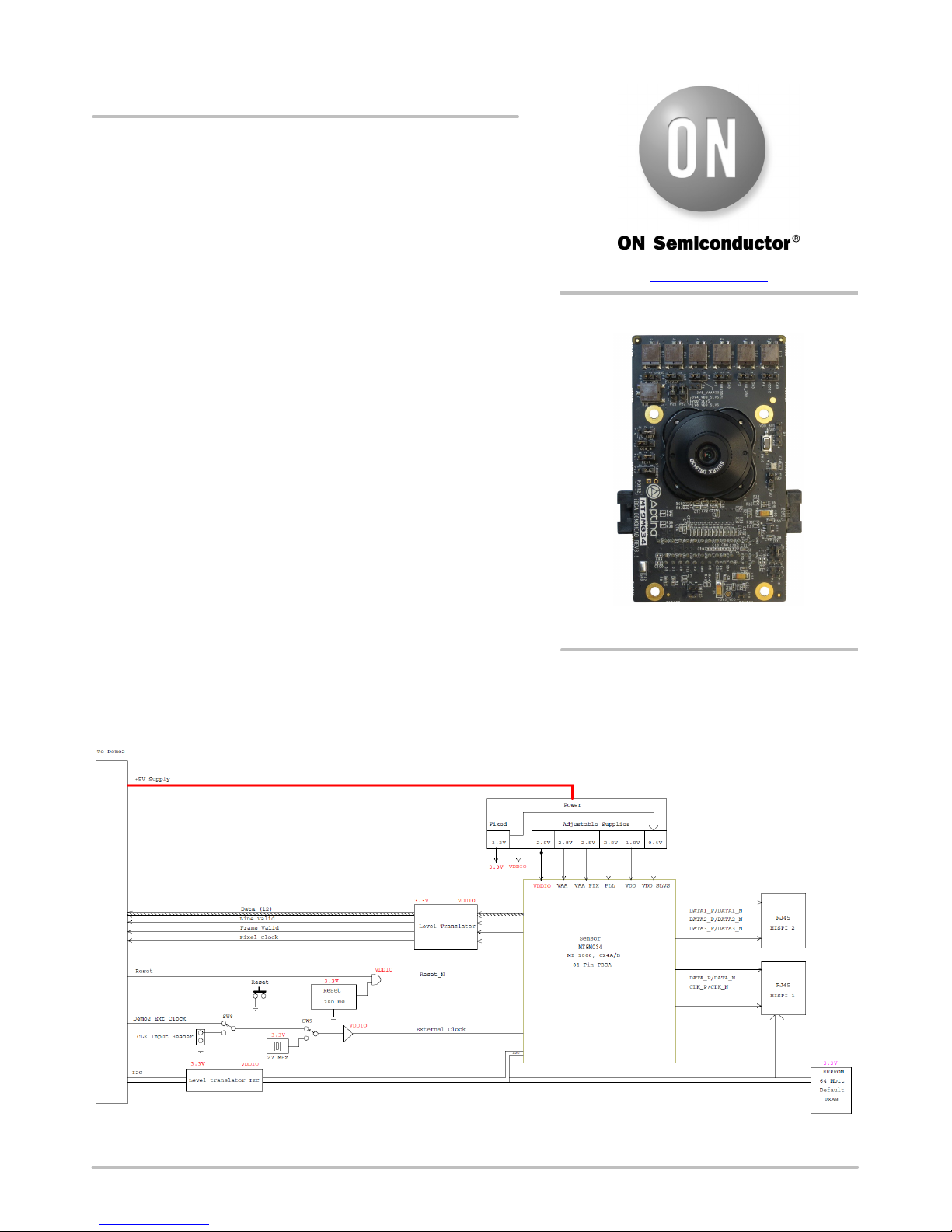
Block Diagram
Figure 2. Block Diagram of MT9M034I12STMVH−GEVB
© Semiconductor Components Industries, LLC, 2016
July, 2016 − Rev. 0
1 Publication Order Number:
EVBUM2437/D
Page 2
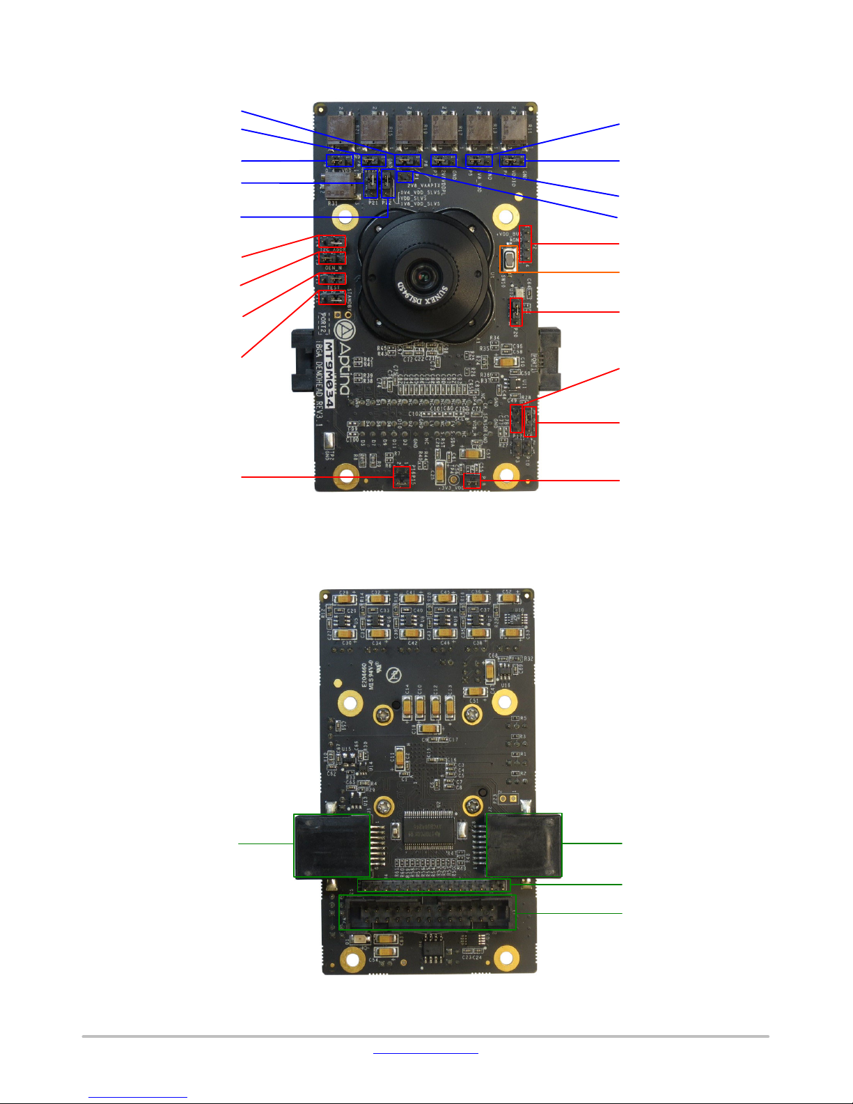
Top View
MT9M034I12STMVH−GEVB
+2V8_VAAPIX P8
+2V8_VAA P6
+0V4_VDD_SLVS P9
+1V8_VDD_SLVS P21
+VDD_SLVS_SEL P22
SADDR P14
OEN_N P13
TEST P11
STANDBY P12
EEPROM ADDR P15, P16
+1V8_VDD P5
+VDDIO P4
+2V8_VDDPLL P7
+VPP P1
FLASH P2
RESET SWITCH SW10
CLK_SELECT P20
TRIGGER P17
MCLK_EN P19
ON_LED P18
Bottom View
HiSPi Connector J1
Figure 3. Top View of Evaluation Board − Default Jumpers
HiSPi Connector J2
Baseboard Connector J4
Baseboard Connector J3
Figure 4. Bottom View of the Evaluation Board − Connectors
www.onsemi.com
2
Page 3

MT9M034I12STMVH−GEVB
Jumper Pin Locations
The jumpers on headboards start with Pin 1 on the leftmost
side of the pin. Grouped jumpers increase in pin size with each
jumper added.
Pin 1
Figure 5. Pin Locations for a Single Jumper. Pin 1 is Located at the Leftmost Side
and Increases as it Moves to the Right
Pin 1
Figure 6. Pin Locations and Assignments of Grouped Jumpers.
Pin 1 is Located at the Top-Left Corner and Increases in a Zigzag Fashion Shown in the Picture
Jumper/Header Functions & Default Positions
Pins 1−4
Pins 1 and 2
Pins 3 and 4
Pins 5 and 6
Pins 7 and 8
Pins 9 and 10
Table 1. JUMPERS AND HEADERS
Jumper/Header No. Jumper/Header Name Pins Description
P1 VPP Open OTPM programming voltage not supplied
P2 FLASH
P4 +VDDIO
P5 +1V8_VDD
P6 +2V8_VAA
P7 +2V8_VDDPLL
P8 +2V8_VAAPIX
1 +VDD_BUS
2 GND
3 FLASH
4 +3V3_VDD
2−3 (Default) Connects to on-board +VDDIO power supply
1−2 External power supply connection
2−3 (Default) Connects to on-board +1V8_VDD power supply
1−2 External power supply connection
2−3 (Default) Connects to on-board +2V8_VAA power supply
1−2 External power supply connection
2−3 (Default) Connects to on-board +2V8_VDDPLL power supply
1−2 External power supply connection
2−3 (Default) Connects to on-board +2V8_VAAPIX power supply
1−2 External power supply connection
www.onsemi.com
3
Page 4

MT9M034I12STMVH−GEVB
Table 1. JUMPERS AND HEADERS (continued)
Jumper/Header No. DescriptionPinsJumper/Header Name
P9 +0V4_VDD_SLVS
P11 TEST
P12 STANDBY
P14 SADDR
P15, P16 EEPROM ADDR
P17 TRIGGER 2 Trigger Input
P18 ON_LED 1−2 (Default) Connects to on-board LED to indicate “power on”
P19 MCLK
P20 CLK_SELECT
P21 +1V8_VDD_SLVS
P22 +VDD_SLVS_SEL
SW10 RESET N/A When pushed, 380 ms reset signal will be sent to MT9M024
2−3 (Default) Connects to on-board +0V4_VDD_SLVS power supply
1−2 External power supply connection
1−2 (Default) Set to Normal Mode
2−3 Set to Test Mode
1−2 (Default) Set to Normal Mode
2−3 Set to Standby Mode
1−2 (Default) I2C address set to 0x20
2−3 I2C address set to 0x30
P15 Closed,
EEPROM Address set to 0xA8
P16 Open (Default)
P15 Open,
EEPROM Address set to 0xAC
P16 Open
P15 Open,
EEPROM Address set to 0xA4
P16 Closed
P15 Closed,
EEPROM Address set to 0xA0
P16 Closed
2−3 (Default) Demo 2X Clock Input Enable
1−2 Demo 2X Clock Input Disable
2−3 (Default) Select on-board oscillator
1−2 Select Demo 2X clock
2−3 (Default) Connects to on-board +1V8_VDD_SLVS power supply
1−2 External power supply connection
2−3 (Default) Connects to on-board +VDD_SLVS_SEL power supply
1−2 External power supply connection
Interfacing to ON Semiconductor Demo 2X Baseboard
The ON Semiconductor Demo 2X baseboard has a
similar 26-pin connector and 13-pin connector which mate
ON Semiconductor and are trademarks of Semiconductor Components Industries, LLC dba ON Semiconductor or its subsidiaries in the United States and/or other countries.
ON Semiconductor owns the rights to a number of patents, trademarks, copyrights, trade secrets, and other intellectual property. A listing of ON Semiconductor’s product/patent
coverage may be accessed at www.onsemi.com/site/pdf/Patent−Marking.pdf
ON Semiconductor makes no warranty, representation or guarantee regarding the suitability of its products for any particular purpose, nor does ON Semiconductor assume any liability
arising out of the application or use of any product or circuit, and specifically disclaims any and all liability, including without limitation special, consequential or incidental damages.
Buyer is responsible for its products and applications using ON Semiconductor products, including compliance with all laws, regulations and safety requirements or standards,
regardless of any support or applications information provided by ON Semiconductor. “Typical” parameters which may be provided in ON Semiconductor data sheets and/or
specifications can and do vary in different applications and actual performance may vary over time. All operating parameters, including “Typicals” must be validated for each customer
application by customer’s technical experts. ON Semiconductor does not convey any license under its patent rights nor the rights of others. ON Semiconductor products are not
designed, intended, or authorized for use as a critical component in life support systems or any FDA Class 3 medical devices or medical devices with a same or similar classification
in a foreign jurisdiction or any devices intended for implantation in the human body. Should Buyer purchase or use ON Semiconductor products for any such unintended or unauthorized
application, Buyer shall indemnify and hold ON Semiconductor and its officers, employees, subsidiaries, affiliates, and distributors harmless against all claims, costs, damages, and
expenses, and reasonable attorney fees arising out of, directly or indirectly, any claim of personal injury or death associated with such unintended or unauthorized use, even if such
claim alleges that ON Semiconductor was negligent regarding the design or manufacture of the part. ON Semiconductor is an Equal Opportunity/Affirmative Action Employer. This
literature is subject to all applicable copyright laws and is not for resale in any manner.
. ON Semiconductor reserves the right to make changes without further notice to any products herein.
with J3 and J4 of the headboard. The four mounting holes
secure the baseboard and the headboard with spacers and
screws.
PUBLICATION ORDERING INFORMATION
LITERATURE FULFILLMENT:
Literature Distribution Center for ON Semiconductor
19521 E. 32nd Pkwy, Aurora, Colorado 80011 USA
Phone: 303−675−2175 or 800−344−3860 Toll Free USA/Canada
Fax: 303−675−2176 or 800−344−3867 Toll Free USA/Canada
Email: orderlit@onsemi.com
N. American Technical Support: 800−282−9855 Toll Free
USA/Canada
Europe, Middle East and Africa Technical Support:
Phone: 421 33 790 2910
Japan Customer Focus Center
Phone: 81−3−5817−1050
www.onsemi.com
ON Semiconductor Website: www.onsemi.com
Order Literature: http://www.onsemi.com/orderlit
For additional information, please contact your local
Sales Representative
EVBUM2437/D
4
 Loading...