

MC100EP016A
查询"MC100EP016A-D"供应商
3.3 V ECL 8-Bit
Synchronous Binary
Up Counter
Description
The MC100EP016A is a high-speed synchronous, presettable,
cascadeable 8-bit binary counter. Architecture and operation are the
same as the ECLinPS™ family MC100E016 with higher operating
speed.
The counter features internal feedback to TC gated by the TCLD
(Terminal Count Load) pin. When TCLD is LOW (or left open, in
which case it is pulled LOW by the internal pulldowns), the TC
feedback is disabled, and counting proceeds continuously, with TC
going LOW to indicate an all-one state. When TCLD is HIGH, the TC
feedback causes the counter to automatically reload upon TC = LOW,
thus functioning as a programmable counter. The Qn outputs do not
need to be terminated for the count function to operate properly. To
minimize noise and power, unused Q outputs should be left
unterminated.
COUT and COUT provide differential outputs from a single,
non-cascaded counter or divider application. COUT and COUT
should not be used in cascade configuration. Only TC should be used
for a counter or divider cascade chain output.
A differential clock input has also been added to improve
performance.
The 100 Series contains temperature compensation.
Features
•550 ps Typical Propagation Delay
•Operation Frequency > 1.3 GHz is 30% Faster than MC100EP016
•PECL Mode Operating Range: V
with VEE = 0 V
•NECL Mode Operating Range: V
with VEE = -3.0 V to -3.6 V
= 3.0 V to 3.6 V
CC
= 0 V
CC
•Open Input Default State
•Safety Clamp on Clock Inputs
•Internal TC Feedback (Gated)
•Addition of COUT and COUT
•8-Bit
•Differential Clock Input
•V
Output
BB
•Fully Synchronous Counting and TC Generation
•Asynchronous Master Reset
•Pb-Free Packages are Available
http://onsemi.com
MARKING
DIAGRAMS*
MC100
LQFP-32
FA SUFFIX
CASE 873A
32
1
QFN32
MN SUFFIX
CASE 488AM
A = Assembly Location
WL = Wafer Lot
YY = Year
WW = Work Week
G or G = Pb-Free Package
(Note: Microdot may be in either location)
*For additional marking information, refer to
Application Note AND8002/D.
See detailed ordering and shipping information in the package
dimensions section on page 11 of this data sheet.
ORDERING INFORMATION
EP016A
AWLYYWWG
1
MC100
EP016A
AWLYYWWG
G
© Semiconductor Components Industries, LLC, 2008
March, 2008 - Rev. 9
1 Publication Order Number:
MC100EP016A/D
MC100EP016A
K
K
查询"MC100EP016A-D"供应商
V
CC
Q3
Q4
Q5
Q6
Q7
TCLD
V
CC
VCCQ2 Q1 Q0 VEEMR CE PE
1
2
3
4
MC100EP016A
5
6
7
8
1514131211109
V
COUT COUT TC VCCP7 P6 P5
EE
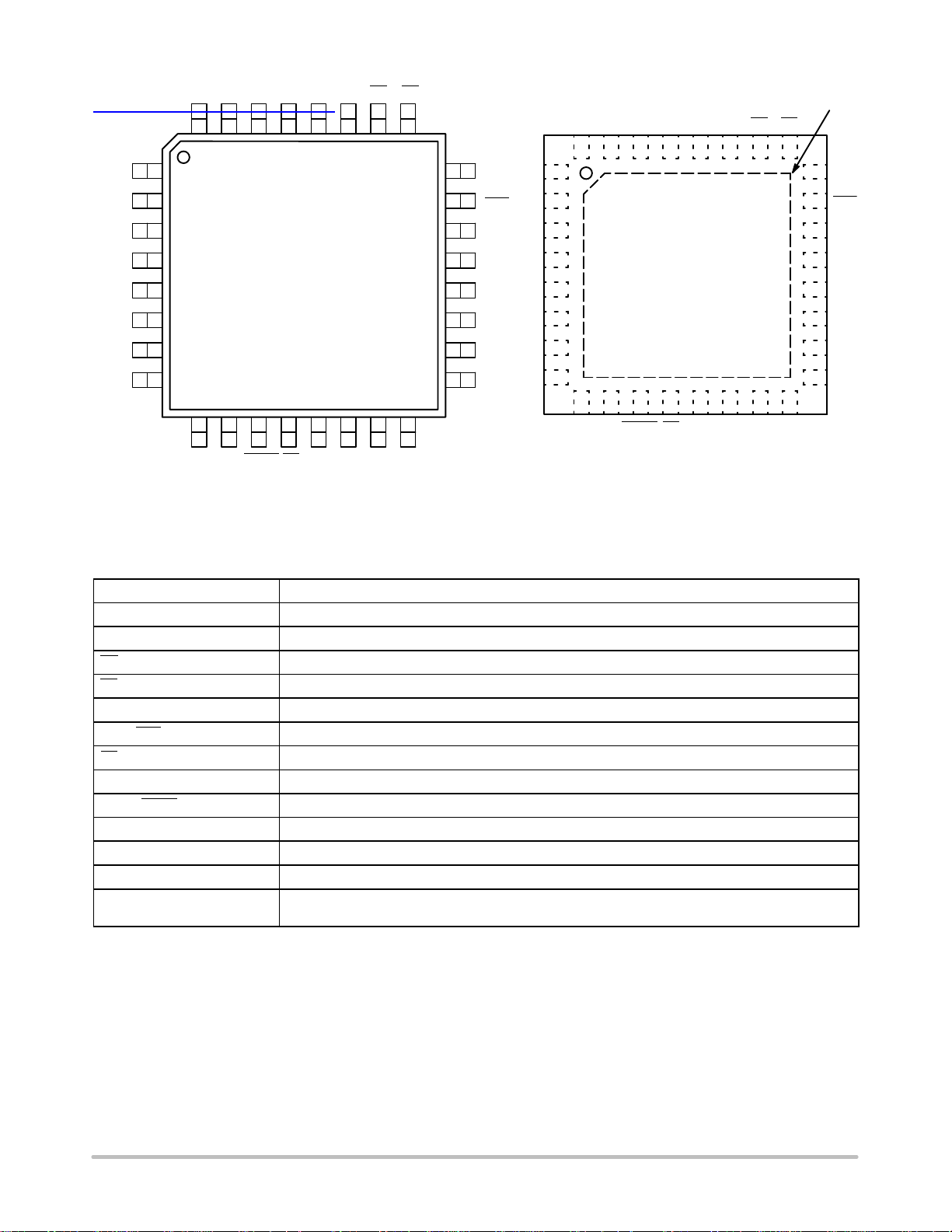
Warning: All VCC and VEE pins must be externally connected to
Power Supply to guarantee proper operation.
Figure 1. 32-Lead LQFP Pinout (Top View)
Exposed Pad
(EP)
VCCQ2 Q1 Q0 VEEMR CE PE
2526272829303132
24
23
22
21
20
19
18
17
V
BB
CLK
CLK
P0
P1
P2
P3
P4
V
CC
Q3
Q4
Q5
Q6
Q7
TCLD
V
CC
1
2
3
4
MC100EP016A
5
6
7
8
16
V
COUT COUT TC VCCP7 P6 P5
EE
2526272829303132
24
V
BB
23
CL
22
CL
21
P0
20
P1
19
P2
18
P3
17
P4
1514131211109
16
Figure 2. 32-Lead QFN Pinout (Top View)
Table 1. PIN DESCRIPTION
Pin Function
P0-P7 ECL Parallel Data (Preset) Inputs
Q0-Q7 ECL Data Outputs
CE* ECL Count Enable Control Input
PE* ECL Parallel Load Enable Control Input
MR* ECL Master Reset
CLK*, CLK* ECL Differential Clock
TC ECL Terminal Count Output
TCLD* ECL TC-Load Control Input
COUT, COUT ECL Differential Output
V
CC
V
EE
V
BB
EP The exposed pad (EP) on the QFN-32 package bottom is thermally connected to the die for improved
*Pins will default LOW when left open.
Positive Supply
Negative Supply
Reference Voltage Output
heat-sinking conduit. The pad is electrically connected to VEE.
http://onsemi.com
2
MC100EP016A
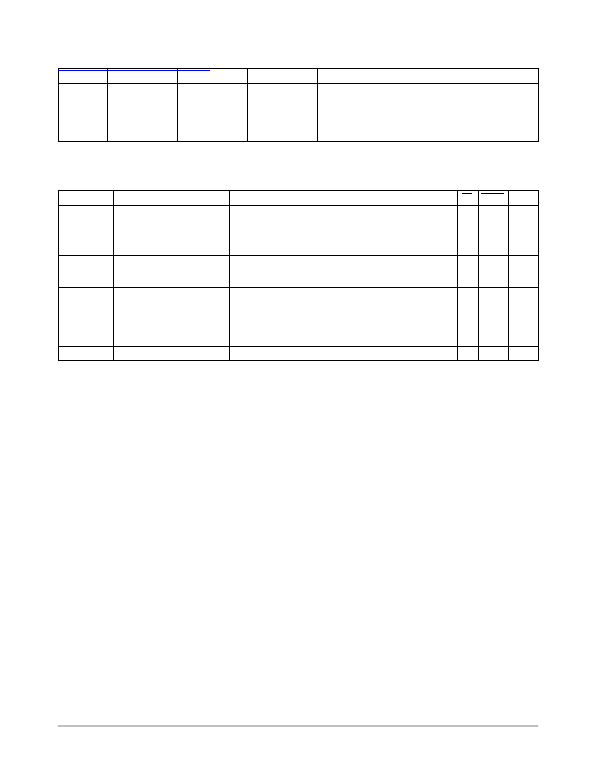
Table 2. FUNCTION TABLE
查询"MC100EP016A-D"供应商
CE PE TCLD MR CLK FUNCTION
X
L
L
H
X
X
ZZ = Clock Pulse (High-to-Low)
Z = Clock Pulse (Low-to-High)
Table 3. FUNCTION TABLE
Function PE CE MR TCLD CLK P7-P4 P3 P2 P1 P0 Q7-Q4 Q3 Q2 Q1 Q0 TC COUT COUT
Load Count L
Load Hold L
Load on
Terminal
Count
Reset X X H X X X X X X X L L L L L H H L
L
H
H
H
X
X
X
H
H
H
H
H
H
H
H
H
H
H
H
L
L
L
L
L
L
L
L
L
X
L
H
L
H
L
L
L
L
L
L
L
L
L
L
L
L
L
X
L
H
X
X
X
X
Z
L
L
L
L
X
X
X
H
H
H
H
H
H
H
Z
X
Z
X
Z
X
Z
X
Z
H
Z
X
Z
X
Z
H
Z
H
Z
H
Z
H
Z
H
Z
H
L
L
L
L
L
H
H
H
X
X
X
X
H
X
X
L
L
L
L
L
L
L
X
X
X
X
X
X
X
X
H
L
X
X
X
X
H
H
H
H
H
H
H
H
H
H
H
H
Z
Z
Z
Z
ZZ
X
L
H
X
H
X
H
X
H
X
L
L
H
X
H
X
H
L
H
L
H
L
H
L
H
L
H
L
H
Load Parallel (Pn to Qn)
Continuous Count
Count; Load Parallel on TC = LOW
Hold
Masters Respond, Slaves Hold
Reset (Qn : = LOW, TC : = HIGH)
H
H
L
L
H
H
H
H
L
H
H
H
H
H
H
L
L
H
L
H
H
H
H
L
L
H
L
H
L
H
L
H
L
H
H
H
H
H
H
H
H
L
L
H
H
H
L
H
H
L
L
H
L
H
L
H
L
H
H
H
L
H
H
L
L
H
H
H
L
H
H
H
H
L
H
H
H
H
H
H
L
H
H
H
L
L
L
H
L
L
L
L
L
L
H
L
L
L
http://onsemi.com
3
MC100EP016A
查询"MC100EP016A-D"供应商
PE
TCLD
CE
P
0
MR
CLK
CLK
V
BB
V
EE
BIT 0
Q0M
Q0M
BIT 1
Q
1
BITS 2-6
CE
Q
Q
Q
Q
0
1
Q
2
3
Q
4
5
Q
6
P7
Q
0
SLAVEMASTER
CE
Q
0
P
1
BIT 7
Q
7
TC
5
COUT
COUT
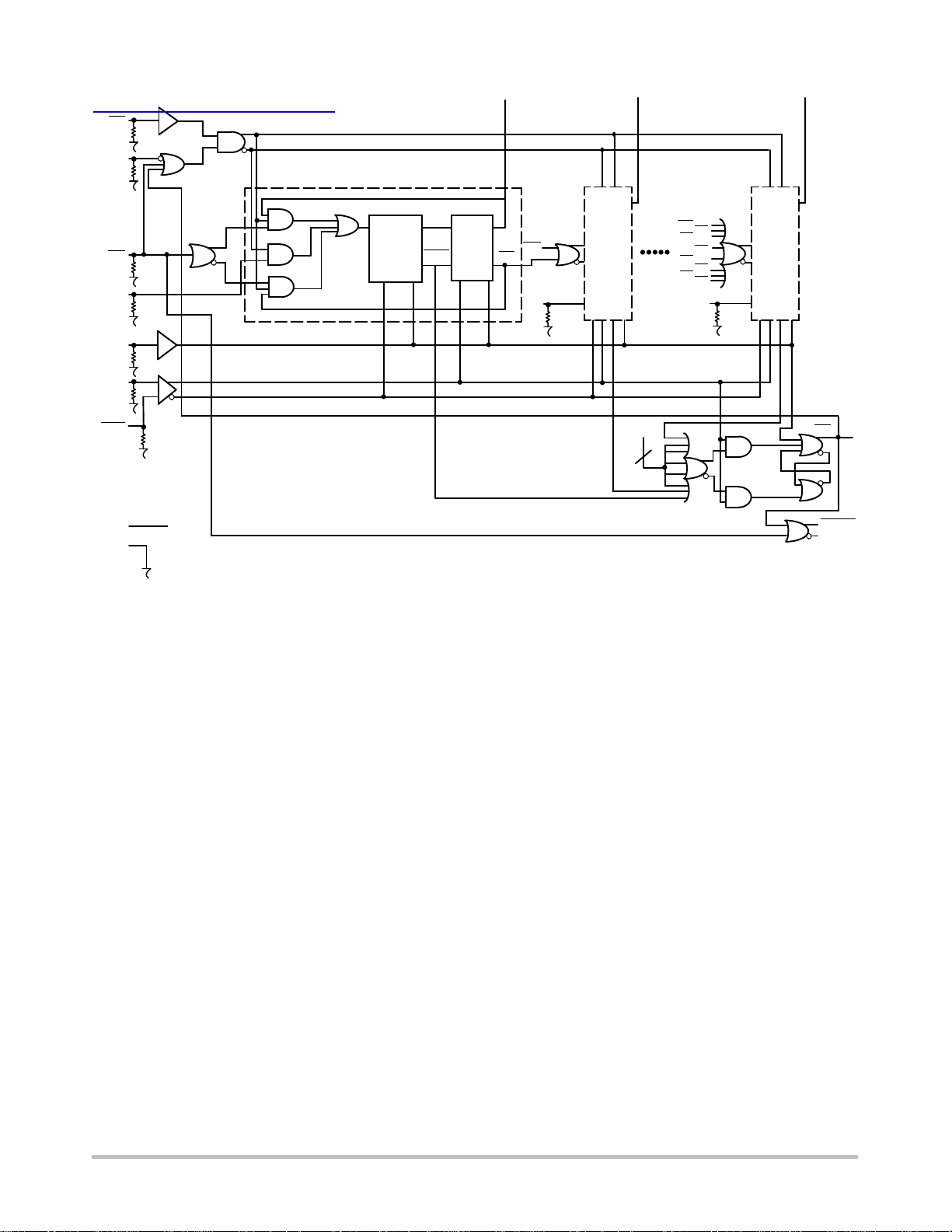
It should not be used for propagation delays as many gate functions are achieved internally without incurring a full gate delay.
Note that this diagram is provided for understanding of logic operation only.
Figure 3. 8‐BIT Binary Counter Logic Diagram
http://onsemi.com
4

MC100EP016A
查询"MC100EP016A-D"供应商
Table 4. ATTRIBUTES
Characteristics Value
Internal Input Pulldown Resistor
75 kW
Internal Input Pullup Resistor N/A
ESD Protection Human Body Model
Machine Model
Charged Device Model
> 2 kV
> 100 V
> 2 kV
Moisture Sensitivity, Indefinite Time Out of Drypack (Note 1) Pb Pkg Pb-Free Pkg
LQFP-32
QFN-32
Level 2
N/A
Level 2
Level 1
Flammability Rating Oxygen Index: 28 to 34 UL 94 V-0 @ 0.125 in
Transistor Count 1226 Devices
Meets or exceeds JEDEC Spec EIA/JESD78 IC Latchup Test
1. For additional information, see Application Note AND8003/D.
Table 5. MAXIMUM RATINGS
Symbol Parameter Condition 1 Condition 2 Rating Unit
V
CC
V
EE
V
I
I
out
I
BB
T
A
T
stg
q
JA
q
JC
q
JA
q
JC
T
sol
Stresses exceeding Maximum Ratings may damage the device. Maximum Ratings are stress ratings only. Functional operation above the
Recommended Operating Conditions is not implied. Extended exposure to stresses above the Recommended Operating Conditions may affect
device reliability.
PECL Mode Power Supply VEE = 0 V 6 V
NECL Mode Power Supply VCC = 0 V -6 V
PECL Mode Input Voltage
NECL Mode Input Voltage
Output Current Continuous
VEE = 0 V
VCC = 0 V
Surge
VI V
VI V
CC
EE
6
-6
50
100
V
V
mA
mA
VBB Sink/Source ± 0.5 mA
Operating Temperature Range -40 to +70 °C
Storage Temperature Range -65 to +150 °C
Thermal Resistance (Junction-to-Ambient) 0 lfpm
500 lfpm
32 LQFP
32 LQFP
74
61
°C/W
°C/W
Thermal Resistance (Junction-to-Case) Standard Board 32 LQFP 12 to 17 °C/W
Thermal Resistance (Junction-to-Ambient) 0 lfpm
500 lfpm
QFN-32
QFN-32
31
27
°C/W
°C/W
Thermal Resistance (Junction-to-Case) 2S2P QFN-32 12 °C/W
Wave Solder Pb
Pb-Free
265
265
°C
http://onsemi.com
5

MC100EP016A
Table 6. 100EP DC CHARACTERISTICS, PECL V
查询"MC100EP016A-D"供应商
= 3.3 V, VEE = 0 V (Note 2)
CC
-40°C 25°C 70°C
Symbol Characteristic
I
EE
V
OH
V
OL
V
IH
V
IL
V
BB
V
IHCMR
Power Supply Current 130 170 210 130 177 210 130 180 210 mA
Output HIGH Voltage (Note 3) 2155 2280 2405 2155 2280 2405 2155 2280 2405 mV
Output LOW Voltage (Note 3) 1355 1480 1605 1355 1480 1605 1355 1480 1605 mV
Input HIGH Voltage (Single-Ended) 2075 2420 2075 2420 2075 2420 mV
Input LOW Voltage (Single-Ended) 1355 1675 1355 1675 1355 1675 mV
Output Voltage Reference 1775 1875 1975 1775 1875 1975 1775 1875 1975 mV
Input HIGH Voltage Common Mode
Range (Differential Configuration)
Min Typ Max Min Typ Max Min Typ Max
2.0 3.3 2.0 3.3 2.0 3.3 V
Unit
(Note 4)
I
IH
I
IL
Input HIGH Current 150 150 150
Input LOW Current 0.5 0.5 0.5
mA
mA
NOTE: Device will meet the specifications after thermal equilibrium has been established when mounted in a test socket or printed circuit
board with maintained transverse airflow greater than 500 lfpm. Electrical parameters are guaranteed only over the declared
operating temperature range. Functional operation of the device exceeding these conditions is not implied. Device specification limit
values are applied individually under normal operating conditions and not valid simultaneously.
2. Input and output parameters vary 1:1 with VCC. VEE can vary +0.3 V to -0.3 V.
3. All loading with 50 ohms to VCC-2.0 volts.
4. V
min varies 1:1 with VEE, V
IHCMR
input signal.
max varies 1:1 with VCC. The V
IHCMR
range is referenced to the most positive side of the differential
IHCMR
Table 7. 100EP DC CHARACTERISTICS, NECL V
= 0 V, V
CC
= -3.6 V to -3.0 V (Note 5)
EE
-40°C 25°C 70°C
Symbol Characteristic
I
EE
V
OH
V
OL
V
IH
V
IL
V
BB
V
IHCMR
Power Supply Current 130 170 210 130 177 210 130 180 210 mA
Output HIGH Voltage (Note 6) -1145 -1020 -895 -1145 -1020 -895 -1145 -1020 -895 mV
Output LOW Voltage (Note 6) -1945 -1820 -1695 -1945 -1820 -1695 -1945 -1820 -1695 mV
Input HIGH Voltage (Single-Ended) -1225 -880 -1225 -880 -1225 -880 mV
Input LOW Voltage (Single-Ended) -1945 -1625 -1945 -1625 -1945 -1625 mV
Output Voltage Reference -1525 -1425 -1325 -1525 -1425 -1325 -1525 -1425 -1325 mV
Input HIGH Voltage Common Mode
Range (Differential Configuration)
Min Ty p Max Min Typ Max Min Typ Max
VEE+2.0 0.0 VEE+2.0 0.0 VEE+2.0 0.0 V
Unit
(Note 7)
I
IH
I
IL
Input HIGH Current 150 150 150
Input LOW Current 0.5 0.5 0.5
mA
mA
NOTE: Device will meet the specifications after thermal equilibrium has been established when mounted in a test socket or printed circuit
board with maintained transverse airflow greater than 500 lfpm. Electrical parameters are guaranteed only over the declared
operating temperature range. Functional operation of the device exceeding these conditions is not implied. Device specification limit
values are applied individually under normal operating conditions and not valid simultaneously.
5. Input and output parameters vary 1:1 with VCC.
6. All loading with 50 ohms to VCC-2.0 volts.
7. V
min varies 1:1 with VEE, V
IHCMR
input signal.
max varies 1:1 with VCC. The V
IHCMR
range is referenced to the most positive side of the differential
IHCMR
http://onsemi.com
6

MC100EP016A
Table 8. AC CHARACTERISTICS V
查询"MC100EP016A-D"供应商
Symbol Characteristic
f
COUNT
Maximum Frequency
Count & Division Modes
Q, TC
, COUT/COUT
t
PLH
t
PHL
Propagation Delay CLK to Q
CLK to COUT/COUT
MR to COUT/COUT
t
S
t
H
t
JITTER
Setup Time P0
Hold Time P0
Clock Random Jitter
(RMS, 1000 Waveforms)
t
t
RR
PW
Reset Recovery Time 400 195 400 205 400 220 ps
Minimum Pulse Width CLK
Minimum Pulse Width MR
tr, t
Output Rise/Fall Times
f
20% - 80%
= -3.0 V to -3.6 V; V
EE
Min Typ Max Min Typ Max Min Typ Max
1.3 1.5 1.2 1.4 1.2 1.3
350
MR to Q
CLK to TC
MR to TC
400
350
400
475
450
400
P1 to P4
P5 to P7
CE
PE
TCLD
300
250
500
500
550
100
P1 to P4
P5 to P7
CE
PE
TCLD
50
150
600
625
525
385
550
90 180 320 100 190 320 125 215 450 ps
0 V or VCC = 3.0 V to 3.6 V; V
CC =
= 0 V (Note 8)
EE
-40°C 25°C 70°C
511
650
400
550
550
511
555
705
720
240
140
80
320
315
355
-145
-160
-105
380
465
320
700
650
700
850
850
400
400
400
500
500
400
300
250
500
500
550
100
50
150
600
625
525
570
550
570
745
760
240
135
65
330
320
365
-155
-170
-110
410
500
325
700
750
700
750
900
900
480
450
480
520
550
570
400
300
250
500
500
550
100
50
150
600
625
525
610
630
610
635
825
830
245
125
55
340
325
380
-170
-180
-115
450
535
340
780
820
780
820
1000
950
2.6 8.5 2.5 8.0 2.5 8.0 ps
334
380
416
550
357
380
416
550
385
380
Unit
GHz
ps
ps
ps
ps
NOTE: Device will meet the specifications after thermal equilibrium has been established when mounted in a test socket or printed circuit
board with maintained transverse airflow greater than 500 lfpm. Electrical parameters are guaranteed only over the declared
operating temperature range. Functional operation of the device exceeding these conditions is not implied. Device specification limit
values are applied individually under normal operating conditions and not valid simultaneously.
8. Measured using a 750 mV source, 50% duty cycle clock source. All loading with 50 ohms to VCC-2.0 V.
http://onsemi.com
7

MC100EP016A
查询"MC100EP016A-D"供应商
Cascading Multiple EP016A Devices
APPLICATIONS INFORMATION
For applications which call for larger than 8‐bit counters
multiple EP016As can be tied together to achieve very wide
bit width counters. The active low terminal count (TC)
output and count enable input (CE) greatly facilitate the
cascading of EP016A devices. Two EP016As can be
cascaded without the need for external gating, however for
counters wider than 16 bits external OR gates are necessary
for cascade implementations.
Figure 4 below pictorially illustrates the cascading of 4
EP016As to build a 32‐bit high frequency counter. Note the
EP01 gates used to OR the terminal count outputs of the
lower order EP016As to control the counting operation of
the higher order bits. When the terminal count of the
preceding device (or devices) goes low (the counter reaches
an all 1s state) the more significant EP016A is set in its count
mode and will count one binary digit upon the next positive
clock transition. In addition, the preceding devices will also
LOAD
count one bit thus sending their terminal count outputs back
to a high state disabling the count operation of the more
significant counters and placing them back into hold modes.
Therefore, for an EP016A in the chain to count, all of the
lower order terminal count outputs must be in the low state.
The bit width of the counter can be increased or decreased
by simply adding or subtracting EP016A devices from
Figure 4 and maintaining the logic pattern illustrated in the
same figure.
The maximum frequency of operation for a cascaded
counter chain is set by the propagation delay of the TC output,
the necessary setup time of the CE input, and the propagation
delay through the OR gate controlling it (for 16-bit counters
the limitation is only the TC propagation delay and the CE
setup time). Figure 4 shows EP01 gates used to control the
count enable inputs, however, if the frequency of operation is
slow enough, a LVECL OR gate can be used. Using the worst
case guarantees for these parameters.
Q0 to Q7
Q0 to Q7Q0 to Q7 Q0 to Q7
PECE
EP016
TC
P0 to P7
CLK
CLK
LO
CLK
CLK CLK
PECE
EP016
LSB
TC
P0 to P7
CLK
Figure 4. 32‐Bit Cascaded EP016A Counter
Note that this assumes the trace delay between the TC
outputs and the CE inputs are negligible. If this is not the
case estimates of these delays need to be added to the
calculations.
Programmable Divider
The EP016A has been designed with a control pin which
makes it ideal for use as an 8‐bit programmable divider. The
TCLD pin (load on terminal count) when asserted reloads the
PECE
EP016
MSB
CLK
CLK
EP01
EP016
CLK
CLK
TC
EP01
P0 to P7 P0 to P7
data present at the parallel input pin (Pn's) upon reaching
terminal count (an all 1s state on the outputs). Because this
feedback is built internal to the chip, the programmable
division operation will run at very nearly the same frequency
as the maximum counting frequency of the device. Figure 5
below illustrates the input conditions necessary for utilizing
the EP016A as a programmable divider set up to divide by
113.
PECE
TC
http://onsemi.com
8

MC100EP016A
查询"MC100EP016A-D"供应商
HLLLHHHH
P7 P6 P4 P3 P2 P1 P0P5
H
PE
L
CE
H
TCLD
CLK
CLK
Q7 Q6 Q4 Q3 Q2 Q1 Q0Q5
APPLICATIONS INFORMATION (continued)
TC
COUT
COUT
Figure 5. Mod 2 to 256 Programmable Divider
To determine what value to load into the device to
accomplish the desired division, the designer simply
subtracts the binary equivalent of the desired divide ratio
from the binary value for 256. As an example for a divide
ratio of 113:
Pn's = 256 - 113 = 8F16 = 1000 1111
where:
P0 = LSB and P7 = MSB
Forcing this input condition as per the setup in Figure 5
will result in the waveforms of Figure 6. Note that the TC
output is used as the divide output and the pulse duration is
equal to a full clock period. For even divide ratios, twice the
desired divide ratio can be loaded into the EP016A and the
TC output can feed the clock input of a toggle flip flop to
create a signal divided as desired with a 50% duty cycle.
Table 9. Preset Values for Various Divide Ratios
Divide
Ratio
2 H H H H H H H L
3 H HHHHH L H
4 H HHHHH L L
5 H HHHH LHH
• • •••••••
• • •••••••
112 H LLHLLLL
113 H L L LHHHH
114 H L L LHHH L
• • •••••••
• • •••••••
254 L LLLLLHL
255 L LLLLLLH
256 L L L L L L L L
P7 P6 P5 P4 P3 P2 P1 P0
Preset Data Inputs
A single EP016A can be used to divide by any ratio from
2 to 256 inclusive. If divide ratios of greater than 256 are
needed multiple EP016As can be cascaded in a manner
similar to that already discussed. When EP016As are
cascaded to build larger dividers the TCLD pin will no
longer provide a means for loading on terminal count.
Because one does not want to reload the counters until all of
the devices in the chain have reached terminal count,
external gating of the TC pins must be used for multiple
EP016A divider chains.
CLK
PE
TC
Load
•••
•••
•••
DIVIDE BY 113
Figure 6. Divide by 113 EP016A Programmable Divider Waveforms
http://onsemi.com
9
Load1001 0000 1001 0001 1111 110 0 1111 11 01 1111 1110 1111 1111

MC100EP016A
查询"MC100EP016A-D"供应商
EP01
Q0 to Q7
Q0 to Q7 Q0 to Q7 Q0 to Q7 Q0 to Q7
LO
CLK
CLK
CLK
CLK
PECE
EP016
LSB
TC
P0 to P7
APPLICATIONS INFORMATION (continued)
PECE
EP016 EP016 EP016
CLK
CLK
TC
P0 to P7 P0 to P7 P0 to P7
Figure 7. 32‐Bit Cascaded EP016A Programmable Divider
Figure 7 shows a typical block diagram of a 32‐bit divider
chain. Once again to maximize the frequency of operation
EP01 OR gates were used. For lower frequency applications
a slower OR gate could replace the EP01. Note that for a
16‐bit divider the OR function feeding the PE (program
enable) input CANNOT be replaced by a wire OR tie as the
TC output of the least significant EP016A must also feed the
CE input of the most significant EP016A. If the two TC
outputs were OR tied the cascaded count operation would
not operate properly. Because in the cascaded form the PE
feedback is external and requires external gating, the
maximum frequency of operation will be significantly less
than the same operation in a single device.
PECE
MSB
CLK
CLK
EP01 EP01
TC
CLK
CLK
Maximizing EP016A Count Frequency
The EP016A device produces 9 fast transitioning single
ended outputs, thus VCC noise can become significant in
situations where all of the outputs switch simultaneously in
the same direction. This VCC noise can negatively impact
the maximum frequency of operation of the device. Since
the device does not need to have the Q outputs terminated to
count properly, it is recommended that if the outputs are not
going to be used in the rest of the system they should be left
unterminated. In addition, if only a subset of the Q outputs
are used in the system only those outputs should be
terminated. Not terminating the unused outputs will not only
cut down the VCC noise generated but will also save in total
system power dissipation. Following these guidelines will
allow designers to either be more aggressive in their designs
or provide them with an extra margin to the published data
book specifications.
PECE
TC
Zo = 50 W
Zo = 50 W
50 W 50 W
V
VTT = VCC - 2.0 V
TT
Receiver
Device
Driver
Device
QD
Q D
Figure 8. Typical Termination for Output Driver and Device Evaluation
(See Application Note AND8020/D - Termination of ECL Logic Devices.)
http://onsemi.com
10

MC100EP016A
ORDERING INFORMATION
查询"MC100EP016A-D"供应商
Device Package Shipping
MC100EP016AFA LQFP-32 250 Units / Tray
MC100EP016AFAG LQFP-32
MC100EP016AFAR2 LQFP-32 2000 / Tape & Reel
MC100EP016AFAR2G LQFP-32
MC100EP016AMNG QFN-32
MC100EP016AMNR4G QFN-32
†For information on tape and reel specifications, including part orientation and tape sizes, please refer to our Tape and Reel Packaging
Specifications Brochure, BRD8011/D.
(Pb-Free)
(Pb-Free)
(Pb-Free)
(Pb-Free)
Resource Reference of Application Notes
AN1405/D - ECL Clock Distribution Techniques
AN1406/D - Designing with PECL (ECL at +5.0 V)
AN1503/D -
AN1504/D - Metastability and the ECLinPS Family
AN1568/D - Interfacing Between LVDS and ECL
AN1672/D - The ECL Translator Guide
AND8001/D - Odd Number Counters Design
AND8002/D - Marking and Date Codes
AND8020/D - Termination of ECL Logic Devices
AND8066/D - Interfacing with ECLinPS
AND8090/D - AC Characteristics of ECL Devices
ECLinPSt I/O SPiCE Modeling Kit
250 Units / Tray
2000 / Tape & Reel
74 Units / Rail
1000 / Tape & Reel
†
http://onsemi.com
11

MC100EP016A
查询"MC100EP016A-D"供应商
A
A1
SEATING
PLANE
9
32
1
-T-
B1
8
9
S1
S
G
-AB-
-AC-
0.10 (0.004) AC
25
DETAIL Y
-Z-
PACKAGE DIMENSIONS
32 LEAD LQFP
CASE 873A-02
ISSUE C
4X
17
4X
-U-
VB
V1
DETAIL AD
T-U0.20 (0.008) ZAB
P
DETAIL Y
T-U0.20 (0.008) ZAC
_
M
8X
E
C
H
W
X
AE
AE
R
K
-T-, -U-, -Z-
BASE
METAL
N
J
SECTION AE-AE
_
Q
T-U
M
DF
0.20 (0.008) ZAC
NOTES:
1.
DIMENSIONING AND TOLERANCING
PER ANSI Y14.5M, 1982.
2.
CONTROLLING DIMENSION:
MILLIMETER.
3.
DATUM PLANE -AB- IS LOCATED AT
BOTTOM OF LEAD AND IS COINCIDENT
WITH THE LEAD WHERE THE LEAD
EXITS THE PLASTIC BODY AT THE
BOTTOM OF THE PARTING LINE.
4.
DATUMS -T-, -U-, AND -Z- TO BE
DETERMINED AT DATUM PLANE -AB-.
5.
DIMENSIONS S AND V TO BE
DETERMINED AT SEATING PLANE -AC-.
6.
DIMENSIONS A AND B DO NOT INCLUDE
MOLD PROTRUSION. ALLOWABLE
PROTRUSION IS 0.250 (0.010) PER SIDE.
DIMENSIONS A AND B DO INCLUDE
MOLD MISMATCH AND ARE
DETERMINED AT DATUM PLANE -AB-.
7.
DIMENSION D DOES NOT INCLUDE
DAMBAR PROTRUSION. DAMBAR
PROTRUSION SHALL NOT CAUSE THE
D DIMENSION TO EXCEED 0.520 (0.020).
8.
MINIMUM SOLDER PLATE THICKNESS
SHALL BE 0.0076 (0.0003).
9.
EXACT SHAPE OF EACH CORNER MAY
VARY FROM DEPICTION.
DETAIL AD
MILLIMETERS
DIMAMIN MAX MIN MAX
7.000 BSC 0.276 BSC
A1 3.500 BSC 0.138 BSC
B 7.000 BSC 0.276 BSC
B1 3.500 BSC 0.138 BSC
C 1.400 1.600 0.055 0.063
D 0.300 0.450 0.012 0.018
E 1.350 1.450 0.053 0.057
F 0.300 0.400 0.012 0.016
G 0.800 BSC 0.031 BSC
H 0.050 0.150 0.002 0.006
J 0.090 0.200 0.004 0.008
K 0.450 0.750 0.018 0.030
__
M 12 REF 12 REF
N 0.090 0.160 0.004 0.006
P 0.400 BSC 0.016 BSC
Q 1 5 1 5
____
R 0.150 0.250 0.006 0.010
S 9.000 BSC 0.354 BSC
S1 4.500 BSC 0.177 BSC
V 9.000 BSC 0.354 BSC
V1 4.500 BSC 0.177 BSC
W 0.200 REF 0.008 REF
X 1.000 REF 0.039 REF
INCHES
0.250 (0.010)
GAUGE PLANE
http://onsemi.com
12

MC100EP016A
l
查询"MC100EP016A-D"供应商
D
TOP VIEW
SIDE VIEW
D2
9
32
A0.10 BC
2 X
32 X
2 X
PIN ONE
LOCATION
0.15 C
0.15 C
0.10 C
0.08 C
32 X
L
32 X
b
0.05 C
8
1
PACKAGE DIMENSIONS
QFN32 5*5*1 0.5 P
CASE 488AM-01
ISSUE O
A
B
E
(A3)
A
SEATING
A1
16
17
24
25
EXPOSED PAD
K
32 X
E2
e
PLANE
C
NOTES:
1. DIMENSIONS AND TOLERANCING PER
2. CONTROLLING DIMENSION: MILLIMETERS.
3. DIMENSION b APPLIES TO PLATED
4. COPLANARITY APPLIES TO THE EXPOSED
SOLDERING FOOTPRINT*
5.30
3.20
32 X
0.63
ASME Y14.5M, 1994.
TERMINAL AND IS MEASURED BETWEEN
0.25 AND 0.30 MM TERMINAL
PAD AS WELL AS THE TERMINALS.
MILLIMETERS
DIM MIN NOM MAX
A 0.800 0.900 1.000
A1 0.000 0.025 0.050
A3 0.200 REF
b 0.180 0.250 0.300
D 5.00 BSC
D2 2.950 3.100 3.250
E 5.00 BSC
E2
2.950 3.100 3.250
e 0.500 BSC
K 0.200 --- ---
L 0.300 0.400 0.500
3.20
5.30
BOTTOM VIEW
32 X
0.28
28 X
0.50 PITCH
*For additional information on our Pb-Free strategy and soldering
details, please download the ON Semiconductor Soldering and
Mounting Techniques Reference Manual, SOLDERRM/D.
ECLinPS is a trademark of Semiconductor Components INdustries, LLC (SCILLC).
ON Semiconductor and are registered trademarks of Semiconductor Components Industries, LLC (SCILLC). SCILLC reserves the right to make changes without further notice
to any products herein. SCILLC makes no warranty, representation or guarantee regarding the suitability of its products for any particular purpose, nor does SCILLC assume any liability
arising out of the application or use of any product or circuit, and specifically disclaims any and all liability, including without limitation special, consequential or incidental damages.
“Typical” parameters which may be provided in SCILLC data sheets and/or specifications can and do vary in different applications and actual performance may vary over time. All
operating parameters, including “Typicals” must be validated for each customer application by customer's technical experts. SCILLC does not convey any license under its patent rights
nor the rights of others. SCILLC products are not designed, intended, or authorized for use as components in systems intended for surgical implant into the body, or other applications
intended to support or sustain life, or for any other application in which the failure of the SCILLC product could create a situation where personal injury or death may occur. Should
Buyer purchase or use SCILLC products for any such unintended or unauthorized application, Buyer shall indemnify and hold SCILLC and its officers, employees, subsidiaries, affiliates,
and distributors harmless against all claims, costs, damages, and expenses, and reasonable attorney fees arising out of, directly or indirectly, any claim of personal injury or death
associated with such unintended or unauthorized use, even if such claim alleges that SCILLC was negligent regarding the design or manufacture of the part. SCILLC is an Equal
Opportunity/Affirmative Action Employer. This literature is subject to all applicable copyright laws and is not for resale in any manner.
PUBLICATION ORDERING INFORMATION
LITERATURE FULFILLMENT:
Literature Distribution Center for ON Semiconductor
P.O. Box 5163, Denver, Colorado 80217 USA
Phone: 303-675-2175 or 800-344-3860 Toll Free USA/Canada
Fax: 303-675-2176 or 800-344-3867 Toll Free USA/Canada
Email: orderlit@onsemi.com
N. American Technical Support: 800-282-9855 Toll Free
USA/Canada
Europe, Middle East and Africa Technical Support:
Phone: 421 33 790 2910
Japan Customer Focus Center
Phone: 81-3-5773-3850
http://onsemi.com
ON Semiconductor Website: www.onsemi.com
Order Literature: http://www.onsemi.com/orderlit
For additional information, please contact your loca
Sales Representative
MC100EP016A/D
13
 Loading...