

Page 1
LC898229XI
AF Control LSI
Overview
This LSI is Closed−Auto Focus control LSI equipped with hall
sensor. It consists of 1 system of feedback circuit and constant current
driver. It has also a built−in EEPROM and temperature sensor.
Features
• Built−in Equalizer Circuit Using Digital Operation
♦ AF Control Equalizer Circuit
♦ Any Coefficient can be Specified by 2−wire Serial I/F (TWIF)
• 2−wire Serial Interface (The communication protocol is compatible
with I2C)
• Built−in A/D Converter
• Built−in D/A Converter
♦ Hall Offset
♦ Constant Current Bias
• Built−in Hall Sensor
♦ Si Hall Sensor
• Built−in EEPROM
♦ 64byte (16byte/page)
• Built−in OSC
• Built−in Constant Current Driver
♦ 110 mA
• Package
♦ WL−CSP 6−pin (2 x 3pin) , Thickness Max 0.29 mm, with
Backside Coat
♦ Lead−free, Halogen−free
• Supply voltage
♦ V
(2.6 V to 3.3 V)
DD
www.onsemi.com
WLCSP
6 BUMP
CASE 567UK
DEVICE MARKING INFORMATION
8229
YMZZ
8229= Specific Device Code
Y = Year
M = Month
ZZ = Assembly Lot
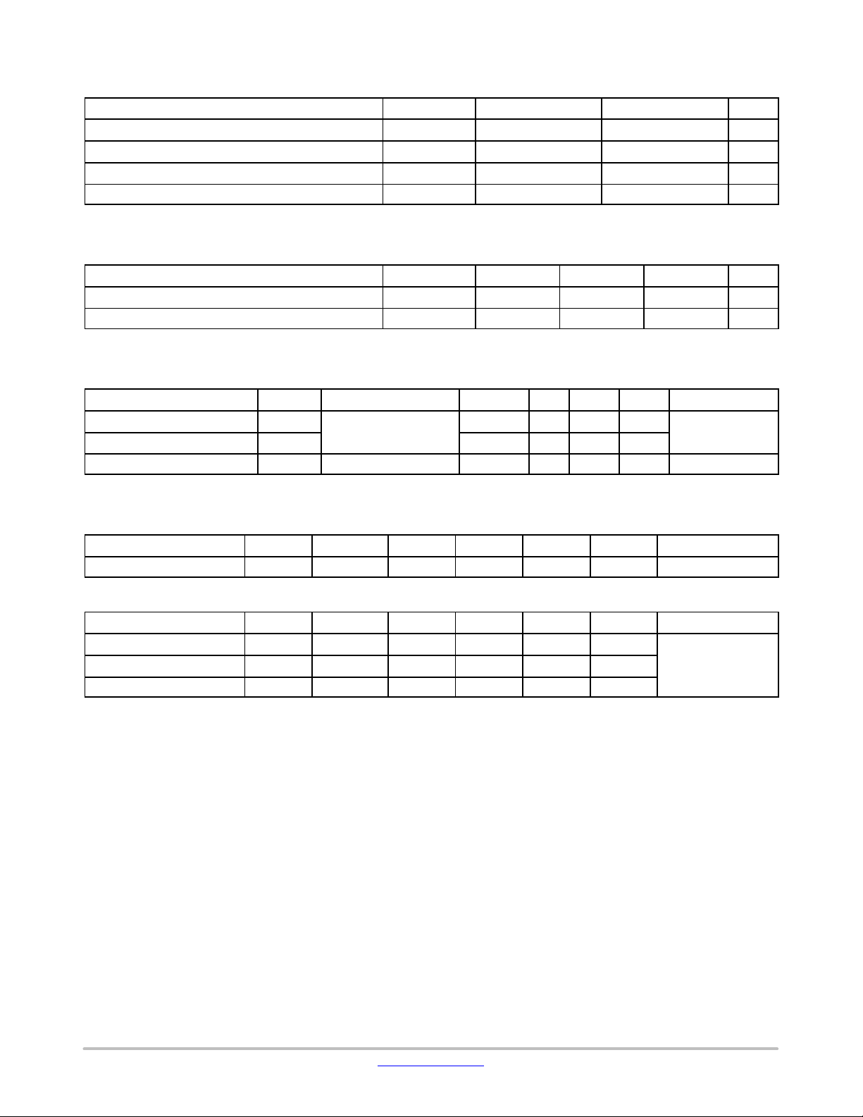
PIN LAYOUT
AB
VDD VSS
3
SDA SCL
2
OUT1 OUT2
1
© Semiconductor Components Industries, LLC, 2017
January , 2018 − Rev. 0
(Top View)
Number of PINsCircuit Name
2Driver
2Power
2Logic
ORDERING INFORMATION
Device Package Shipping
LC898229XI WLCSP6 4000 / Tape &
†For information on tape and reel specifications,
including part orientation and tape sizes, please
refer to our Tape and Reel Packaging Specification
Brochure, BRD8011/D.
1 Publication Order Number:
LC898229XI/D
†
Reel
Page 2
Pin Description
Type
I Input
O Output
B Bidirection
P Power supply, GND
NC Not Connected
2−wire Serial Interface
SCL I 2−wire serial interface clock pin
SDA B 2−wire serial interface data pin
Driver Interface
OUT1 O Driver output (to Actuator)
OUT2 O Driver output (to Actuator)
Power Supply Pin
V
DD
V
SS
P Power supply
P GND
LC898229XI
*Process when Pins are Not Used
PIN TYPE “O” – Ensure that it is set to OPEN.
PIN TYPE “I” – OPEN is inhibited. Ensure that it is
connected to the VDD or VSS even when it is unused.
(Please contact ON Semiconductor for more information
about selection of VDD or VSS.)
PIN TYPE “B” – If you are unsure about processing method
on the pin description of pin layout table, please contact us.
Note that incorrect processing of unused pins may result
in defects.
www.onsemi.com
2
Page 3
LC898229XI
Table 1. ABSOLUTE MAXIMUM RATING (VSS = 0 V)
Item
Supply voltage VDD33 max Ta ≤ 25°C
Input/output voltage VI33, VO33 Ta ≤ 25°C
Storage ambient temperature Tstg
Operating ambient temperature Topr
Stresses exceeding those listed in the Maximum Ratings table may damage the device. If any of these limits are exceeded, device functionality
should not be assumed, damage may occur and reliability may be affected.
Table 2. ACCEPTABLE OPERATION RANGE at Ta = −30 ~ 70°C, VSS = 0 V
Item Symbol Min Typ Max Unit
Supply voltage VDD33 2.6 2.8 3.3 V
Input voltage range V
Functional operation above the stresses listed in the Recommended Operating Ranges is not implied. Extended exposure to stresses beyond
the Recommended Operating Ranges limits may affect device reliability.
Table 3. DC CHARACTERISTICS: Input/output level at VSS = 0 V, VDD = 2.6 V ~ 3.3V, Ta = −30 ~ 70°C
Item Symbol Condition Min Typ Max Unit Applicable Pins
High−level input voltage V
Low−level input voltage V
Low−level output voltage V
Product parametric performance is indicated in the Electrical Characteristics for the listed test conditions, unless otherwise noted. Product
performance may not be indicated by the Electrical Characteristics if operated under different conditions.
IH
IL
OL
CMOS compliant
IOL= 2mA
Symbol Condition Rating Unit
−0.3~4.6
−0.3~VDD33+0.3
−55~125
−30~70
IN
Schmidt
0 VDD33 V
1.4 V
0.4 V
0.2
V SDA
V
V
°C
°C
SCL, SDA
Table 4. DRIVER OUTPUT (OUT1, OUT2) at VSS = 0 V, VDD = 2.8 V, Ta = 25°C
Item Symbol Condition Min Typ Max Unit Applicable Pins
Maximum current I
full
105 110 115 mA OUT1, OUT2
Table 5. NON−VOLATILE MEMORY CHARACTERISTICS
Item Symbol Condition Min Typ Max Unit Applicable Circuit
Endurance EN 1000 Cycles
Data retention RT 10 Years
Write time t
WT
EEPROM
20 ms
www.onsemi.com
3
Page 4

LC898229XI
SDA
SCL
Hall VGA
Hall
Offset
/Bias
AD
OUT1
OUT2
2−Wire
Serial I /F
EEPROM
Control
logic
EQ
OSC POR LDO
Constant
Current
Driver
OUT1
OUT2
VDD
more than or
equal to 0.1uF (*)
VSS
Figure 1. Block Diagram
NOTE: Consider capacitance of capacitor between VDD and VSS. According to power source environment, attach an additional capacitor
in camera module.
Figure 2. Hall Element Position
NOTE: Please refer to package diagram for each dimension.
www.onsemi.com
unit: mm(typ)
4
Page 5

VDD Supply Timing
VDD
VSS
LC898229XI
AC Characteristics
t2
t3
t1
Vbot
SCL/SDA
Figure 3. VDD Supply Timing
It is available to use 2−wire serial interface 5ms later for Power On Reset of VDD.
Item Symbol Min Typ Max Unit
VDD turn on time t1 3 ms
2−wire serial interface start time from VDD on t2 5 ms
VDD off time t3
Bottom Voltage Vbot 0.1 V
100
ms
www.onsemi.com
5
Page 6

LC898229XI
AC Specification
Figure 4 shows interface timing definition and Table 6 shows electric characteristics.
VIHmin
SDA
SCL
VILmax
tf
tLOW
tHD,STAtSU,STAtSU,DATtHD,DAT
VIHmin
VILmax
tBUF
tr
tSU,STO
Stop
Condition
Start
Condition
Start
Condition
tr tftHD,STA
Repeated
Condition
Figure 4. 2−wire Serial Interface Timing Definition
Table 6. ELECTRIC CHARACTERISTICS for 2−wire Serial Interface (AC Characteristics)
Fast−mode Fast−mode Plus
Item Symbol Pin Name
SCL clock frequency FSCL SCL 400
START condition hold time tHD, STA SCL, SDA 0.6 0.26
SCL clock Low period t
SCL clock High period t
Setup time for repetition
LOW
HIGH
tSU, STA SCL, SDA 0.6 0.26
SCL 1.3 0.5
SCL 0.6 0.26
START condition
Data hold time tHD, DAT SCL, SDA 0 (Note 1) 0.9 0 (Note 1)
Data setup time tSU, DAT SCL, SDA 100
SDA, SCL rising time t
SDA, SCL falling time t
r
f
SCL, SDA 300
SCL, SDA 300
STOP condition setup time tSU, STO SCL, SDA 0.6 0.26
Bus free time between STOP
and START
t
BUF
SCL, SDA 1.3 0.5
1. This LSI is designed for a condition with typ. 20ns of hold time. If SDA signal is unstable around falling point of SCL signal, please implement
an appropriate treatment on board, such as inserting a resistor.
Min Typ Max Min Typ Max
1000
50
120
120
Units
KHz
ms
ms
ms
ms
ms
ns
ns
ns
ms
ms
www.onsemi.com
6
Page 7

MECHANICAL CASE OUTLINE
PACKAGE DIMENSIONS
SCALE 4:1
PIN A1
REFERENCE
0.05 C
0.03 C
E
TOP VIEW
DETAIL A
SIDE VIEW
e
B
A
123
BOTTOM VIEW
RECOMMENDED
SOLDERING FOOTPRINT*
1
A
A
A
C
e
6X
0.03
PACKAGE
OUTLINE
B
D
SEATING
PLANE
b
C
0.40
PITCH
WLCSP6 0.86x1.70x0.265
CASE 567UK
ISSUE A
BACKSIDE
COATING
A1
DETAIL A
A0.05 BC
DATE 22 MAY 2017
NOTES:
1. DIMENSIONING AND TOLERANCING PER ASME
Y14.5M, 1994.
2. CONTROLLING DIMENSION: MILLIMETERS.
3. DATUM C, THE SEATING PLANE, IS DEFINED BY
THE SPHERICAL CROWNS OF CONTACT BALLS.
4. COPLANARITY APPLIES TO SPHERICAL CROWNS
OF CONTACT BALLS.
5. DIMENSION b IS MEASURED AT THE MAXIMUM
CONTACT BALL DIAMETER PARALLEL TO DATUM C.
A3
MILLIMETERS
DIMAMIN NOM
0.24
A1 0.04 REF
A3
b 0.12 0.17
D
E 1.65 1.70
e 0.40 BSC
0.265
0.025 REF
0.81 0.86
MAX
0.29
0.22
0.91
1.75
GENERIC
MARKING DIAGRAM*
XXXX
ALYW
A = Assembly Location
L = Wafer Lot
Y = Year
W = Work Week
*This information is generic. Please refer to
device data sheet for actual part marking.
Pb−Free indicator, “G” or microdot “ G”,
may or may not be present. Some products
may not follow the Generic Marking.
6X
0.40
PITCH
DIMENSIONS: MILLIMETERS
0.17
*For additional information on our Pb−Free strategy and soldering
details, please download the ON Semiconductor Soldering and
Mounting Techniques Reference Manual, SOLDERRM/D.
DOCUMENT NUMBER:
DESCRIPTION:
ON Semiconductor and are trademarks of Semiconductor Components Industries, LLC dba ON Semiconductor or its subsidiaries in the United States and/or other countries.
ON Semiconductor reserves the right to make changes without further notice to any products herein. ON Semiconductor makes no warranty, representation or guarantee regarding
the suitability of its products for any particular purpose, nor does ON Semiconductor assume any liability arising out of the application or use of any product or circuit, and specifically
disclaims any and all liability, including without limitation special, consequential or incidental damages. ON Semiconductor does not convey any license under its patent rights nor the
rights of others.
© Semiconductor Components Industries, LLC, 2019
98AON64224G
WLCSP6 0.86x1.70x0.265
Electronic versions are uncontrolled except when accessed directly from the Document Repository.
Printed versions are uncontrolled except when stamped “CONTROLLED COPY” in red.
PAGE 1 OF 1
www.onsemi.com
Page 8

ON Semiconductor and are trademarks of Semiconductor Components Industries, LLC dba ON Semiconductor or its subsidiaries in the United States and/or other countries.
ON Semiconductor owns the rights to a number of patents, trademarks, copyrights, trade secrets, and other intellectual property. A listing of ON Semiconductor ’s product/patent
coverage may be accessed at www.onsemi.com/site/pdf/Patent−Marking.pdf
ON Semiconductor makes no warranty, representation or guarantee regarding the suitability of its products for any particular purpose, nor does ON Semiconductor assume any liability
arising out of the application or use of any product or circuit, and specifically disclaims any and all liability, including without limitation special, consequential or incidental damages.
Buyer is responsible for its products and applications using ON Semiconductor products, including compliance with all laws, regulations and safety requirements or standards,
regardless of any support or applications information provided by ON Semiconductor. “Typical” parameters which may be provided in ON Semiconductor data sheets and/or
specifications can and do vary in different applications and actual performance may vary over time. All operating parameters, including “Typicals” must be validated for each customer
application by customer’s technical experts. ON Semiconductor does not convey any license under its patent rights nor the rights of others. ON Semiconductor products are not
designed, intended, or authorized for use as a critical component in life support systems or any FDA Class 3 medical devices or medical devices with a same or similar classification
in a foreign jurisdiction or any devices intended for implantation in the human body. Should Buyer purchase or use ON Semiconductor products for any such unintended or unauthorized
application, Buyer shall indemnify and hold ON Semiconductor and its officers, employees, subsidiaries, affiliates, and distributors harmless against all claims, costs, damages, and
expenses, and reasonable attorney fees arising out of, directly or indirectly, any claim of personal injury or death associated with such unintended or unauthorized use, even if such
claim alleges that ON Semiconductor was negligent regarding the design or manufacture of the part. ON Semiconductor is an Equal Opportunity/Affirmative Action Employer. This
literature is subject to all applicable copyright laws and is not for resale in any manner.
. ON Semiconductor reserves the right to make changes without further notice to any products herein.
PUBLICATION ORDERING INFORMATION
LITERATURE FULFILLMENT:
Email Requests to: orderlit@onsemi.com
ON Semiconductor Website: www.onsemi.com
TECHNICAL SUPPORT
North American Technical Support:
Voice Mail: 1 800−282−9855 Toll Free USA/Canada
Phone: 011 421 33 790 2910
Europe, Middle East and Africa Technical Support:
Phone: 00421 33 790 2910
For additional information, please contact your local Sales Representative
◊
www.onsemi.com
1
 Loading...