

Page 1
LB11685AV
f
Monolithic Digital IC
3‐phase Sensor Less Motor
Driver
Overview
The LB11685AV is a three-phase full-wave current-linear-drive
motor driver IC. It adopts a sensor less control system without the use
of a Hall Effect device. For quieter operation, the LB11685AV
features a current soft switching circuit and be optimal for driving the
cooling fan motors used in refrigerators, etc.
Functions
• Three-phase Full-wave Linear Drive (Hall Sensor-less Method)
• Built-in Current Limiter Circuit
• Built-in Three-phase Output Voltage Control Circuit
• Built-in Motor Lock Protection Circuit
• Motor Lock Protection Detection Output
• FG Output Made by Back EMF
• Built-in Thermal Shut Down Circuit
• Beat Lock Prevention Circuit
Specifications
www.onsemi.com
SSOP24J
CASE 565AS
MARKING DIAGRAM
XXXXXXXXXX
YMDDD
MAXIMUM RATINGS
Parameter
Maximum Supply
Voltage
Input Applied
Voltage
Maximum Output
Current
Allowable Power
Dissipation
Operating
Temperature
Storage
Temperature
Junction
Temperature
Stresses exceeding those listed in the Maximum Ratings table may damage the
device. If any of these limits are exceeded, device functionality should not be
assumed, damage may occur and reliability may be affected.
1. The I
2. Specified board: 76.1 mm × 114.3 mm × 1.6 mm, glass epoxy board.
CAUTION: Absolute maximum ratings represent the value which cannot be
CAUTION: Even when the device is used within the range of absolute
is a peak value of motor-current.
O
exceeded for any length of time.
maximum ratings, as a result of continuous usage under high
temperature, high current, high voltage, or drastic temperature
change, the reliability of the IC may be degraded. Please
contact us for the further details.
(TA = 25°C)
Symbol Conditions Ratings Unit
VCC max 19 V
VIN max −0.3 to VCC + 0.3 V
IO max
(Note 1)
Pd max Mounted on
T
T
Tj max 150
a board (Note 2)
opr
stg
1.2 A
1.05 W
−40 to +85 °C
−55 to +150
°C
°C
XXXXX = Specific Device Code
Y = Year
M = Month
DDD = Additional Traceability Data
PIN ASSIGNMENT
24 VOUTUOUT 1
23 WOUT(NC) 2
22 (NC)(NC) 3
21 (NC)PGND 4
20 RFMCOM 5
(NC) 6
11
CO
19 V
18 REGSGND 7
17 VOHFG 8
16 FC1RD 9
15 FC2(NC) 10
14 C2V
13 C1CX 12
CC
ORDERING INFORMATION
See detailed ordering and shipping information on page 7 o
this data sheet.
© Semiconductor Components Industries, LLC, 2013
January , 2018 − Rev. 1
1 Publication Order Number:
LB11685AV/D
Page 2
LB11685AV
RECOMMENDED OPERATING CONDITIONS (T
Symbol
V
CC
Recommended Supply Voltage 12.0 V
Parameter Conditions Ratings Unit
= 25°C)
A
VCC op Operating Supply Voltage 4.5 to 18.0 V
Functional operation above the stresses listed in the Recommended Operating Ranges is not implied. Extended exposure to stresses beyond
the Recommended Operating Ranges limits may affect device reliability.
ELECTRICAL CHARACTERISTICS (T
Symbol
I
CC
Supply Current FC1 = FC2 = 0 V 5 10 20 mA
Parameter Conditions Min Typ Max Unit
= 25°C unless otherwise noted)
C
VREG Internal Regulate Voltage 3.0 3.3 3.6 V
VOSOUR Output Voltage (Source) IO = 0.8 A (Note 5) 1.3 1.7 V
VOSINK Output Voltage (Sink) IO = 0.8 A (Note 5) 0.5 1.3 V
VOLIM Current Limiter 0.268 0.300 0.332 V
VINCOM MCOM Pin
0 VCC − 2 V
Common-input Voltage Range
ICOM+ MCOM Pin
MCOM = 7 V 30 80
mA
Source Current for Hysteresis
ICOM− MCOM Pin
MCOM = 7 V 30 80
mA
Sink Current for Hysteresis
RTCOM MCOM Pin
RTCOM = ICOM+ / ICOM− 0.6 1.4
Hysteresis Current Ratio
I
VCO
f
min VCO Oscillation Minimum Frequency
VCO
f
max VCO Oscillation Maximum Frequency
VCO
I
CX
DVCX
IC1(2)+ C1 (C2) Charge Current VCO = 2.5 V , C1(2) = 1.3V 12 20 28
IC1(2)− C1 (C2) Discharge Current VCO = 2.5 V , C1(2) = 1.3V 12 20 28
VCO Input Bias Current VCO = 2.3 V 0.2
VCO = 2.1 V , CX = 0.015mF
930 Hz
Design target (Note 4)
VCO = 2.7 V , CX = 0.015mF
8.6 kHz
Design target (Note 4)
CX Charge/Discharge Current VCO = 2.5 V , CX = 1.6V 70 100 140
CX Hysteresis Voltage 0.35 0.55 0.75
mA
mA
mA
mA
RTC1(2) C1 (C2) Charge/Discharge Current Ratio RTC1(2) = IC1(2)+ / IC1(2)− 0.8 1.0 1.2
RTCCHG C1/C2 Charge Current Ratio RTCCHG = IC1+ / IC2+ 0.8 1.0 1.2
RTCDIS C1/C2 Discharge Current Ratio RTCDIS = IC1− / IC2− 0.8 1.0 1.2
VCW1(2) C1 (C2) Cramp Voltage Width 1.0 1.3 1.6 V
VFGL FG Output Low Level Voltage IFG = 3 mA 0.5 V
VRDL RD Output Low Level Voltage IRD = 3mA 0.5 V
TTSD Thermal Shut Down Operating Temperature
(Note 3)
DTTSD
Thermal Shut Down Hysteresis Temperature
(Note 3)
Junction temperature
Design target (Note 4)
Junction temperature
Design target (Note 4)
150 180 °C
15
°C
Product parametric performance is indicated in the Electrical Characteristics for the listed test conditions, unless otherwise noted. Product
performance may not be indicated by the Electrical Characteristics if operated under different conditions.
3. The thermal shut down circuit is built-in for protection from damage of IC. But its operation is out of T
operation.
. Design thermal calculation at normal
opr
4. Design target value and no measurement is made.
5. The I
is a peak value of motor-current.
O
www.onsemi.com
2
Page 3
LB11685AV
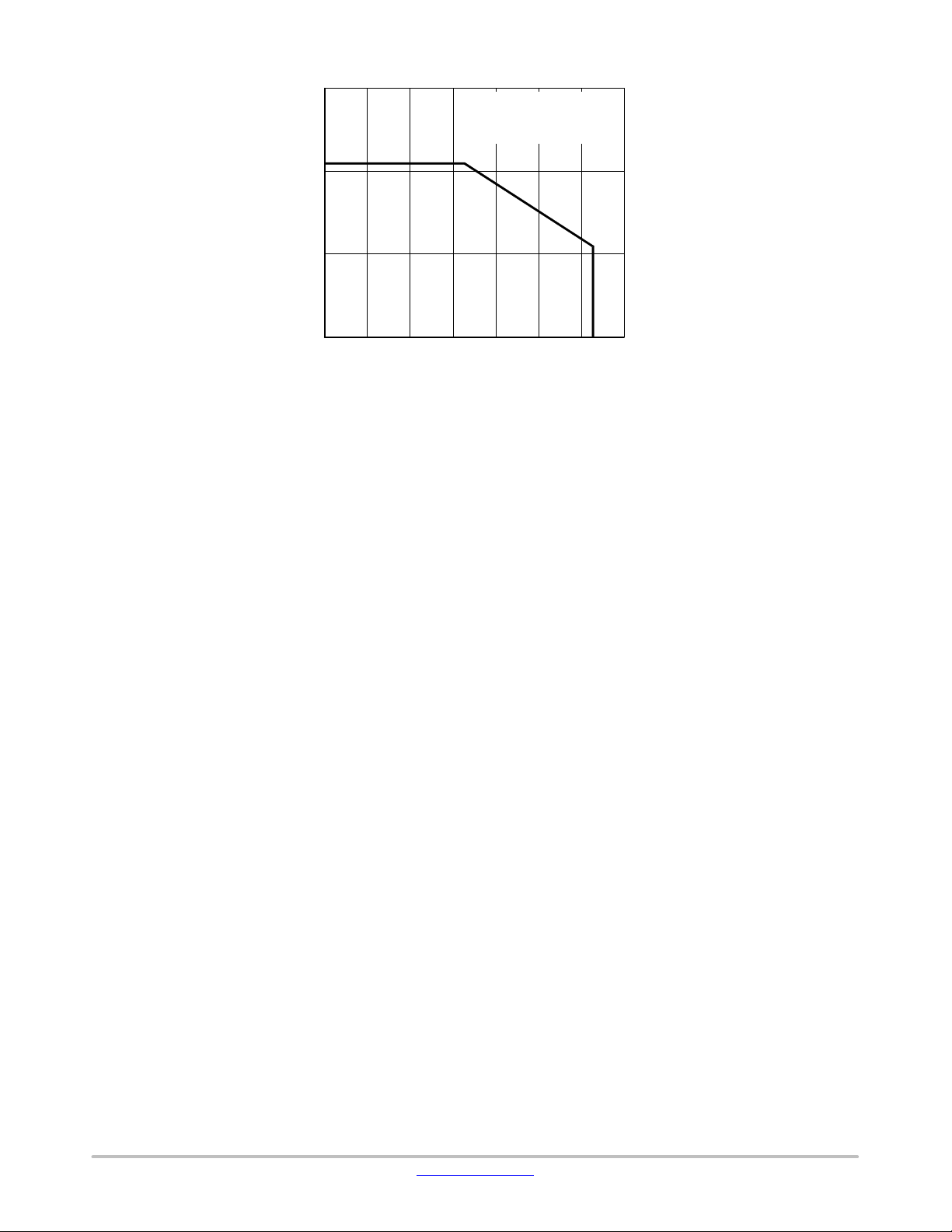
1.5
1.0
max (W)
d
P
0.5
Allowable Power Dissipation,
0
−40 −20 0 20 40 60 80 100
Ambient Temperature, T
Figure 1. Pd max − T
Specified circuit board:
114.3 × 76.1 × 1.6 mm
glass epoxy board
1.05
(5C)
A
A
3
0.55
www.onsemi.com
3
Page 4

LB11685AV
BLOCK DIAGRAM
241
232
Output Switching
Control
Start Up
&
Mask Timing
Power On Reset
Motor Lock
Detector
FG
Pre Drive
Distributor
Reference
Voltage
Bandgap
TSD
Torque Ripple
Rejection &
Current Limit
223
214
205
196
187
178
169
PLL
VCO
1510
Low Voltage
Control
1411
Soft
Switching
1312
Figure 2. Block Diagram
www.onsemi.com
4
Page 5

LB11685AV
PIN FUNCTION
PIN FUNCTION
Pin No. Pin Name Function Equivalent Circuit
1
23
24
4 PGND GND pin in the output part.
20 RF Pin to detect output current.
5 MCOM Motor coil midpoint input pin.
UOUT
WOUT
VOUT
Each output pin of three phases.
This pin is connected to GND. The SGND pin is
also connected to GND
By connecting a resistor between this pin and
, the output current is detected as a voltage.
V
CC
The current limiter is operated by this voltage.
The coil voltage waveform is detected based on
this voltage.
Pin No. 20
Pin No. 4
SGND SGND SGND
V
CC
Pin No. 1, 23, 24
V
CC
7 SGND Ground pin (except the output part)
This pin is connected to GND.
The PGND pin is also connected to GND.
8 FG FG out made by back EMF pin.
It synchronizes FG out with inverted V-phase.
When don’t use this function, open this pin.
9 RD Motor lock protection detection output pin.
Output with L during rotation of motor.
Open during lock protection of motor
(High-impedance).
When don’t use this function, open this pin.
11 VCO PLL output pin and VCO input pin.
To stabilize PLL output, connect a capacitor
between this pin and GND.
Pin No. 5
Pin No. 8, 9
Pin No. 11
VREG
V
CC
SGND
SGND
SGND
VREG
SGND
SGND
VREG
500 kW
www.onsemi.com
5
SGND
Page 6

LB11685AV
PIN FUNCTION (continued)
Pin No. Equivalent CircuitFunctionPin Name
12 CX VCO oscillation output pin.
Operation frequency range and minimum
frequency are determined by the capacity of the
capacitor connected to this pin.
13
14
15 FC2 Frequency characteristic correction pin 2.
C1
C2
Soft switching adjustment pin.
The triangular wave from is form formed by
connecting a capacitor with this pin.
And, the switching of three-phase output is
adjusted by the slope.
To suppress the oscillation of control system
closed loop of sink-side, connect a capacitor
between this pin and GND.
Pin No. 12
Pin No. 13, 14
Pin No. 15
VREG
V
SGND
V
CC
SGND
SGND
SGND
CC
V
CC
SGND
VREG
16 FC1 Frequency characteristic correction pin 1.
To suppress the oscillation of control system
closed loop of source-side, connect a capacitor
between this pin and GND.
17 VOH Three-phase output high level output pin.
To stabilize the output voltage of this pin,
connect a capacitor between this pin and the
V
pin.
CC
18 VREG DC voltage (3.3 V) output pin.
Connect a capacitor between this pin and GND
for stabilization.
19 VCC Pin to supply power-supply voltage.
To curb the influence of ripple and noise.
The voltage should be stabilized.
Pin No. 16
Pin No. 17
Pin No. 18
V
SGND
SGND
SGND
SGND
CC
V
CC
V
CC
V
SGND
SGND
CC
SGND
V
CC
www.onsemi.com
6
Page 7

LB11685AV
APPLICATION CIRCUIT EXAMPLE
* Each fixed number in the following Figure 3, is the referential value.
0.1 mF
FAN MOTOR
0.1 mF0.1 mF
1 mF
0.015 mF
10
11
12
1
2
3
4
5
6
7
8
9
24
23
22
21
20
19
18
17
16
15
14
13
1 mF
0.1 mF
0.1 mF
0.01 mF
10 mF
0.01 mF
0.1 mF
V
CC
1 mF
Figure 3. Application Circuit Example
ORDERING INFORMATION
Device Package Wire Bond Shipping† (Qty / Packing)
LB11685AV−TLM−H SSOP24J (275mil)
(Pb-Free / Halogen Free)
LB11685AV−W−AH SSOP24J (275mil)
(Pb-Free / Halogen Free)
†For information on tape and reel specifications, including part orientation and tape sizes, please refer to our Tape and Reel Packaging
Specifications Brochure, BRD8011/D.
Au-wire 2000 / Tape & Reel
Cu-wire 2000 / Tape & Reel
www.onsemi.com
7
Page 8

MECHANICAL CASE OUTLINE
PACKAGE DIMENSIONS
SSOP24J (275mil)
CASE 565AS
ISSUE A
DATE 31 OCT 2013
SOLDERING FOOTPRINT*
(Unit: mm)
1.00
GENERIC
MARKING DIAGRAM*
XXXXXXXXXX
YMDDD
7.00
XXXXX = Specific Device Code
Y = Year
0.80
NOTE: The measurements are not to guarantee but for reference only.
*For additional information on our Pb−Free strategy and soldering
details, please download the ON Semiconductor Soldering and
Mounting Techniques Reference Manual, SOLDERRM/D.
DOCUMENT NUMBER:
DESCRIPTION:
ON Semiconductor and are trademarks of Semiconductor Components Industries, LLC dba ON Semiconductor or its subsidiaries in the United States and/or other countries.
ON Semiconductor reserves the right to make changes without further notice to any products herein. ON Semiconductor makes no warranty, representation or guarantee regarding
the suitability of its products for any particular purpose, nor does ON Semiconductor assume any liability arising out of the application or use of any product or circuit, and specifically
disclaims any and all liability, including without limitation special, consequential or incidental damages. ON Semiconductor does not convey any license under its patent rights nor the
rights of others.
98AON66070E
SSOP24J (275MIL)
0.42
Electronic versions are uncontrolled except when accessed directly from the Document Repository.
Printed versions are uncontrolled except when stamped “CONTROLLED COPY” in red.
M = Month
DDD = Additional Traceability Data
*This information is generic. Please refer to
device data sheet for actual part marking.
Pb−Free indicator, “G” or microdot “ G”,
may or may not be present.
PAGE 1 OF 1
© Semiconductor Components Industries, LLC, 2019
www.onsemi.com
Page 9

ON Semiconductor and are trademarks of Semiconductor Components Industries, LLC dba ON Semiconductor or its subsidiaries in the United States and/or other countries.
ON Semiconductor owns the rights to a number of patents, trademarks, copyrights, trade secrets, and other intellectual property. A listing of ON Semiconductor ’s product/patent
coverage may be accessed at www.onsemi.com/site/pdf/Patent−Marking.pdf
ON Semiconductor makes no warranty, representation or guarantee regarding the suitability of its products for any particular purpose, nor does ON Semiconductor assume any liability
arising out of the application or use of any product or circuit, and specifically disclaims any and all liability, including without limitation special, consequential or incidental damages.
Buyer is responsible for its products and applications using ON Semiconductor products, including compliance with all laws, regulations and safety requirements or standards,
regardless of any support or applications information provided by ON Semiconductor. “Typical” parameters which may be provided in ON Semiconductor data sheets and/or
specifications can and do vary in different applications and actual performance may vary over time. All operating parameters, including “Typicals” must be validated for each customer
application by customer’s technical experts. ON Semiconductor does not convey any license under its patent rights nor the rights of others. ON Semiconductor products are not
designed, intended, or authorized for use as a critical component in life support systems or any FDA Class 3 medical devices or medical devices with a same or similar classification
in a foreign jurisdiction or any devices intended for implantation in the human body. Should Buyer purchase or use ON Semiconductor products for any such unintended or unauthorized
application, Buyer shall indemnify and hold ON Semiconductor and its officers, employees, subsidiaries, affiliates, and distributors harmless against all claims, costs, damages, and
expenses, and reasonable attorney fees arising out of, directly or indirectly, any claim of personal injury or death associated with such unintended or unauthorized use, even if such
claim alleges that ON Semiconductor was negligent regarding the design or manufacture of the part. ON Semiconductor is an Equal Opportunity/Affirmative Action Employer. This
literature is subject to all applicable copyright laws and is not for resale in any manner.
. ON Semiconductor reserves the right to make changes without further notice to any products herein.
PUBLICATION ORDERING INFORMATION
LITERATURE FULFILLMENT:
Email Requests to: orderlit@onsemi.com
ON Semiconductor Website: www.onsemi.com
TECHNICAL SUPPORT
North American Technical Support:
Voice Mail: 1 800−282−9855 Toll Free USA/Canada
Phone: 011 421 33 790 2910
Europe, Middle East and Africa Technical Support:
Phone: 00421 33 790 2910
For additional information, please contact your local Sales Representative
◊
www.onsemi.com
1
 Loading...