

Page 1

Is Now Part of
To learn more about ON Semiconductor, please visit our website at
www.onsemi.com
ON Semi conductor an d the ON Semico nductor logo a re trademar ks of Semicon ductor Comp onents Indus tries, L LC dba ON Semico nductor or it s subsidiari es in the United S tates and /or other coun tries. ON Se miconducto r owns the righ ts to a number
of patents, trademarks, copyrights, trade secrets, and other intellectual property. A listing of ON Semiconductor’s product/patent coverage may be accessed at www.onsemi.com/site/pdf/Patent-Marking.pdf. ON Semiconductor reserve s the right
to make changes without f urther noti ce to any produc ts herein. ON S emicon ductor makes no warran ty, representat ion or guar antee regar ding the suitability of its pro ducts for any partic ular purpose, n or does ON Semic onductor as sume any liabilit y
arisin g out of the applica tion or us e of any product o r circui t, and specific ally dis claims any and all lia bilit y, includin g witho ut limit ation sp ecial, c onsequential or incidental da mages . Buye r is responsib le for it s products and a pplica tions us ing ON
Semic onductor pr oducts, inc luding complia nce with all law s, regulati ons and safet y requirem ents or stan dards, rega rdless of an y support or ap plications in formation p rovided by ON S emiconduc tor. “Typical ” parameter s which may be pr ovided in ON
Semic onductor data s heet s and/or s pecificatio ns can and do vary in diff erent a pplica tions an d actual perf ormance may var y over time. All o perat ing parameter s, including “Typical s” must b e validated for e ach cus tomer ap plicat ion by customer’s
techni cal exper ts. ON Semic onductor do es not conve y any license un der its pate nt rights no r the rights o f others. ON S emiconduc tor produc ts are not des igned, inte nded, or autho rized for use a s a critical c omponent in lif e support s ystems or an y FDA
Clas s 3 medical devi ces or medica l devices wit h a same or similar c lassificat ion in a foreign j urisdictio n or any device s intended for im plantation in t he human body. Sho uld Buyer pur chase or use ON S emiconduct or products f or any such unint ended
or unaut horized appli cation, Buy er shall indemn ify and hold O N Semiconduc tor and its of ficers, e mployees , subsidiari es, affilia tes, and dis tributor s harmless ag ainst all claim s, costs , damages, an d expenses , and reason able attorn ey fees aris ing out
of, dire ctly or indire ctly, any claim o f personal inj ury or death as sociated w ith such unint ended or unauth orized use, e ven if such claim a lleges that ON S emiconduc tor was neglig ent regardin g the design or ma nufacture o f the part. ON S emiconduct or
is an Equa l Oppor tunity/Affirm ative Action E mployer. This li terature is s ubject to all applicable c opyright la ws and is no t for resale in any manner.
Page 2
FAN7529
Critical Conduction Mode PFC Controller
FAN7529 Critical Conduction Mode PFC Controller
April 2007
Features
Low Total Harmonic Distortion (THD)
Precise Adjustable Output Over-Voltage Protection
Open-Feedback Protection and Disable Function
Zero Current Detector
150µs Internal Start-up Timer
MOSFET Over-Current Protection
Under-Voltage Lockout with 3.5V Hysteresis
Low Start-up (40µA) and Operating Current (1.5mA)
Totem Pole Output with High State Clamp
+500/-800mA Peak Gate Drive Current
8-Pin DIP or 8-Pin SOP
Applications
Adapter
Ballast
LCD TV, CRT TV
SMPS
Related Application Notes
AN-6026 - Design of Power Factor Correction Circuit
Using FAN7529
Description
The FAN7529 is an active power factor correction (PFC)
controller for boost PFC applications that operates in critical conduction mode (CRM). It uses the voltage mode
PWM that compares an internal ramp signal with the
error amplifier output to generate MO SFET turn-off signal. Because the voltage-mode CRM PFC controller does
not need rectified AC line voltage inform ation, it saves the
power loss of the input voltage sensing netwo rk necessary for the current-mode CRM PFC controller.
FAN7529 provides many protection functions, such as
over-voltage protection, open-feedback protection, overcurrent protection, and under-voltage lockout protection.
The FAN7529 can be disabled if the INV pin voltage is
lower than 0.45V and the operating current decreases to
65µA. Using a new variable on-time control method,
THD is lower than the conventional CRM boost PFC ICs.
Ordering Information
Operating T emp.
Part Number
FAN7529N -40°C to +125°C Yes 8-DIP Rail FAN7529
FAN7529M -40°C to +125°C Yes 8-SOP Rail FAN7529
FAN7529MX -40°C to +125°C Yes 8-SOP Tape & Reel FAN7529
© 2006 Fairchild Semiconductor Corporation www.fairchildsemi.com
FAN7529 Rev. 1.0.2
Range Pb-Free Package Packing Method
Marking
Code
Page 3
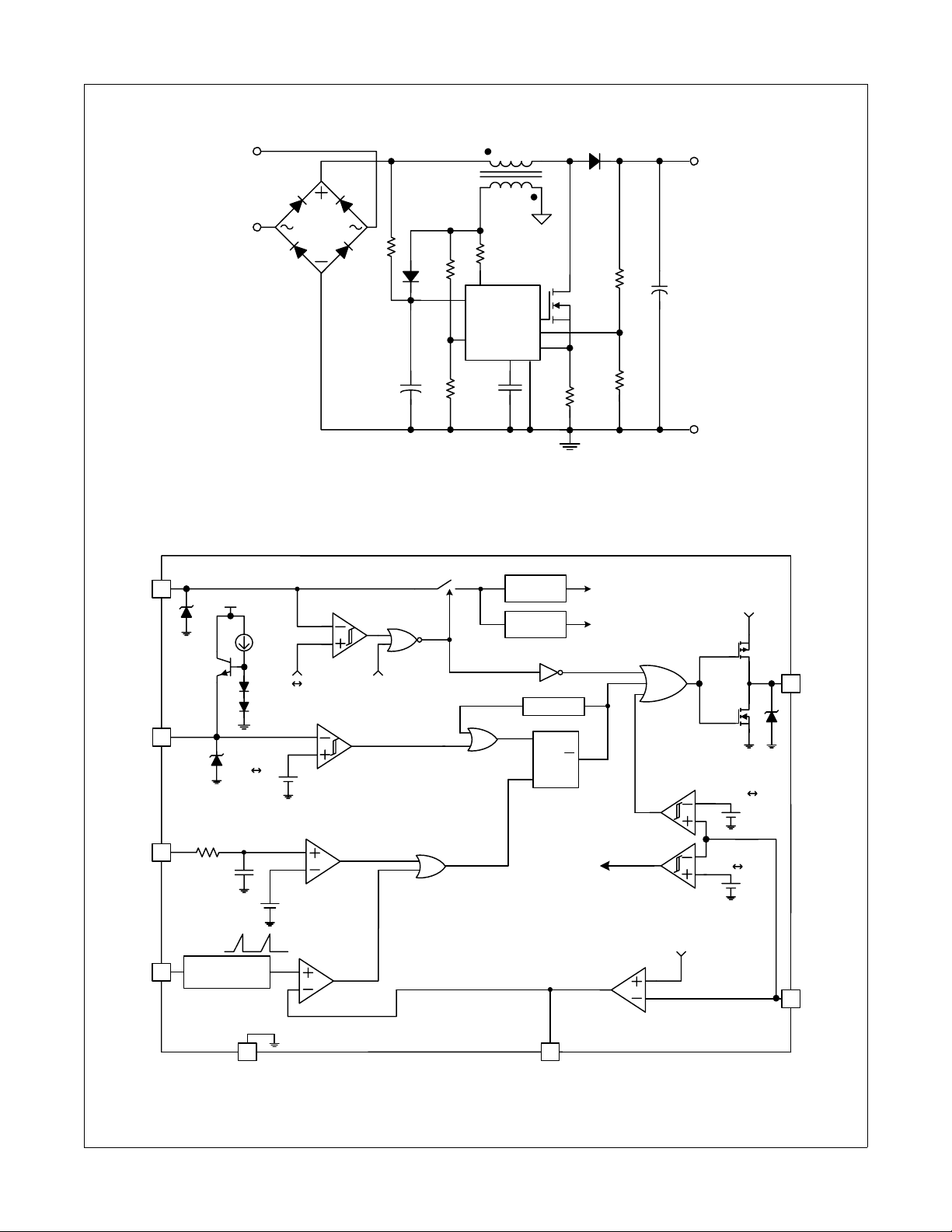
Typical Application Diagrams
AC
IN
Figure 1. Typical Boost PFC Application
FAN7529 Critical Conduction Mode PFC Controller
LD
N
V
AUX
R2
V
CC
AUX
R
ZCD
ZCD
FAN7529
INV
MOT
CS
COMP
R1
GND
V
O
C
O
FAN7529 Rev. 00
Internal Block Diagram
8
V
CC
8.5V
12V
5
ZCD
CS
MOT
4
3
2.9V
6.7V
40k
8pF
Ramp
Signal
Saw Tooth
Generator
1.4V
0.8V
1.5V
Current Protection
Comparator
1V Offset
UVLO
Disable
Zero Current
Detector
2.5V
Ref
Internal
Bias
Timer
S
R
Q
Error
Amplifier
1V~5V
Range
V
ref1
Disable
Gm
OVP
V
ref1
V
CC
Drive
Output
2.675V
2.5V
0.45V 0.35V
7
OUT
1
INV
6
GND
2
COMP
FAN7529 Rev. 00
Figure 2. Functional Block Diagram of FAN7529
© 2006 Fairchild Semiconductor Corporation www.fairchildsemi.com
FAN7529 Rev. 1.0.2 2
Page 4
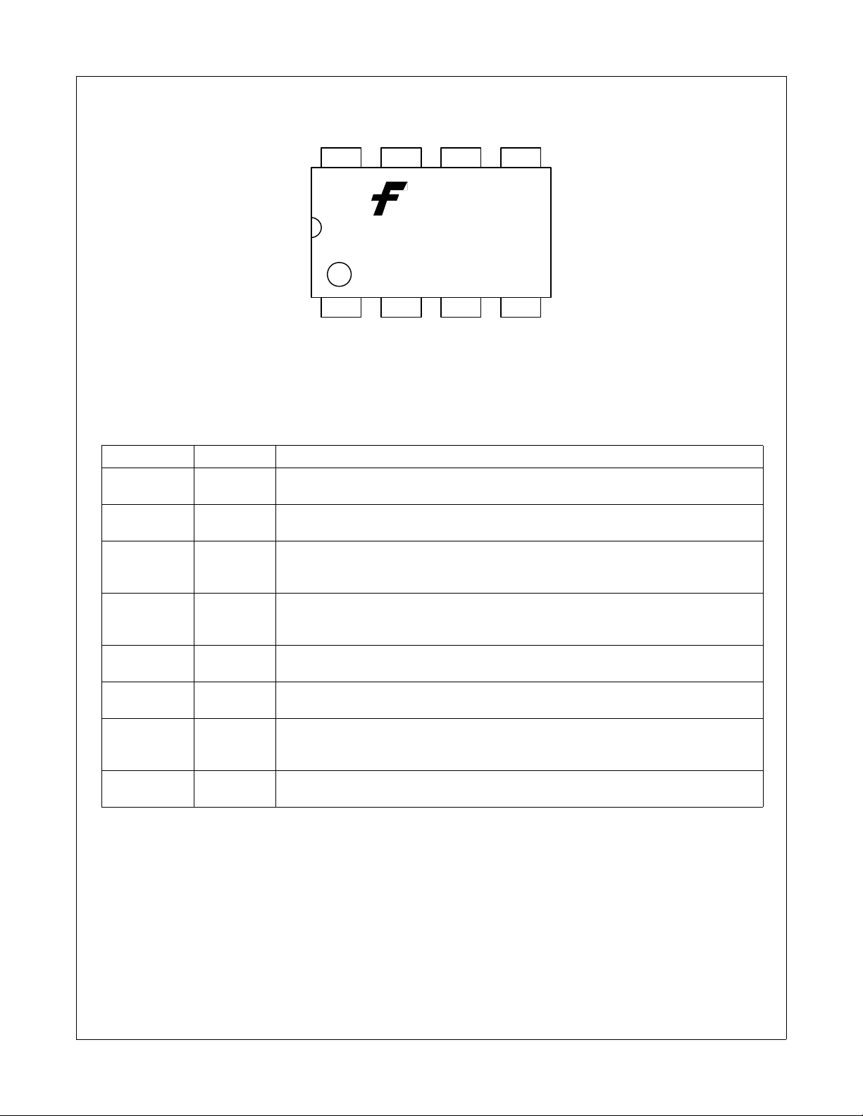
Pin Assignments
FAN7529 Critical Conduction Mode PFC Controller
V
CC
OUT GND ZCD
6 58 7
YWW
FAN7529
1 2 3 4
COMP CSMOTINV
Figure 3. Pin Configuration (Top View)
Pin Definitions
Pin # Name Description
1INV
2COMP
3MOT
4CS
5ZCD
6GND
7OUT
8V
CC
This pin is the inverting input of the error amplifier. The output voltage of the boost PFC
converter should be resistively divided to 2.5V.
This pin is the output of the transconductance error amplifier. Components for output
voltage compensation should be connected between this pin and GND.
This pin is used to set the slope of the internal ramp. The voltage of this pin is maintained at 2.9V . If a resistor is connected between this pin and GND, current flows out of
the pin and the slope of the internal ramp is proportional to this current.
This pin is the input of the over-current protection comparator. The MOSFET current is
sensed using a sensing resistor and the resulting voltage is appl ied to this pin. An
internal RC filter is included to filter switching noise.
This pin is the input of the zero current detection block. If the voltage of this pin goes
higher than 1.5V, then goes lower than 1.4V, the MOSFET is turned on.
This pin is used for the ground potential of all the pins. For proper operation, the signal
ground and the power ground should be separated.
This pin is the gate drive output. The peak sourcing and sinking current levels are
+500mA and -800mA respectively. For proper operation, the stray inductance in the
gate driving path must be minimized.
This pin is the IC supply pin. IC current and MOSFET drive current are supplied using
this pin.
FAN7529 Rev. 00
© 2006 Fairchild Semiconductor Corporation www.fairchildsemi.com
FAN7529 Rev. 1.0.2 3
Page 5
Absolute Maximum Ratings
Stresses exceeding the absolute maximum ratings may damage the device. The device may not function or be operable above the recommended operating conditions and stressing the parts to these levels is not recommended. In addition, extended exposure to stresses above the recommended operating cond itions may affect device reliability. The
absolute maximum ratings are stress ratings only. T
Symbol Parameter Value Unit
V
CC
, I
I
OH
I
clamp
I
det
V
IN
T
J
T
A
T
STG
V
ESD_HBM
V
ESD_MM
V
ESD_CDM
OL
Supply Voltage V
Peak Drive Output Current +500/-800 mA
Driver Output Clamping Diodes VO>VCC or VO<-0.3V ±10 mA
Detector Clamping Diodes ±10 mA
Error Amplifier, MOT, CS Input Voltages -0.3 to 6 V
Operating Junction Temperature 150 °C
Operating Temperature Range -40 to 125 °C
Storage Temperature Range -65 to 150 °C
ESD Capability, Human Body Model 2.0 kV
ESD Capability, Machine Model 300 V
ESD Capability, Charged Device Model 500 V
= 25°C unless otherwise specified.
A
Z
V
FAN7529 Critical Conduction Mode PFC Controller
Thermal Impedance
(1)
Symbol Parameter Value Unit
θ
JΑ
Thermal Resistance, Junction-to-Ambient
Note:
1. Regarding the test environment and PCB type, please refer to JESD51-2 and JESD51-10.
© 2006 Fairchild Semiconductor Corporation www.fairchildsemi.com
FAN7529 Rev. 1.0.2 4
8-DIP 110 °C/W
8-SOP 150 °C/W
Page 6
FAN7529 Critical Conduction Mode PFC Controller
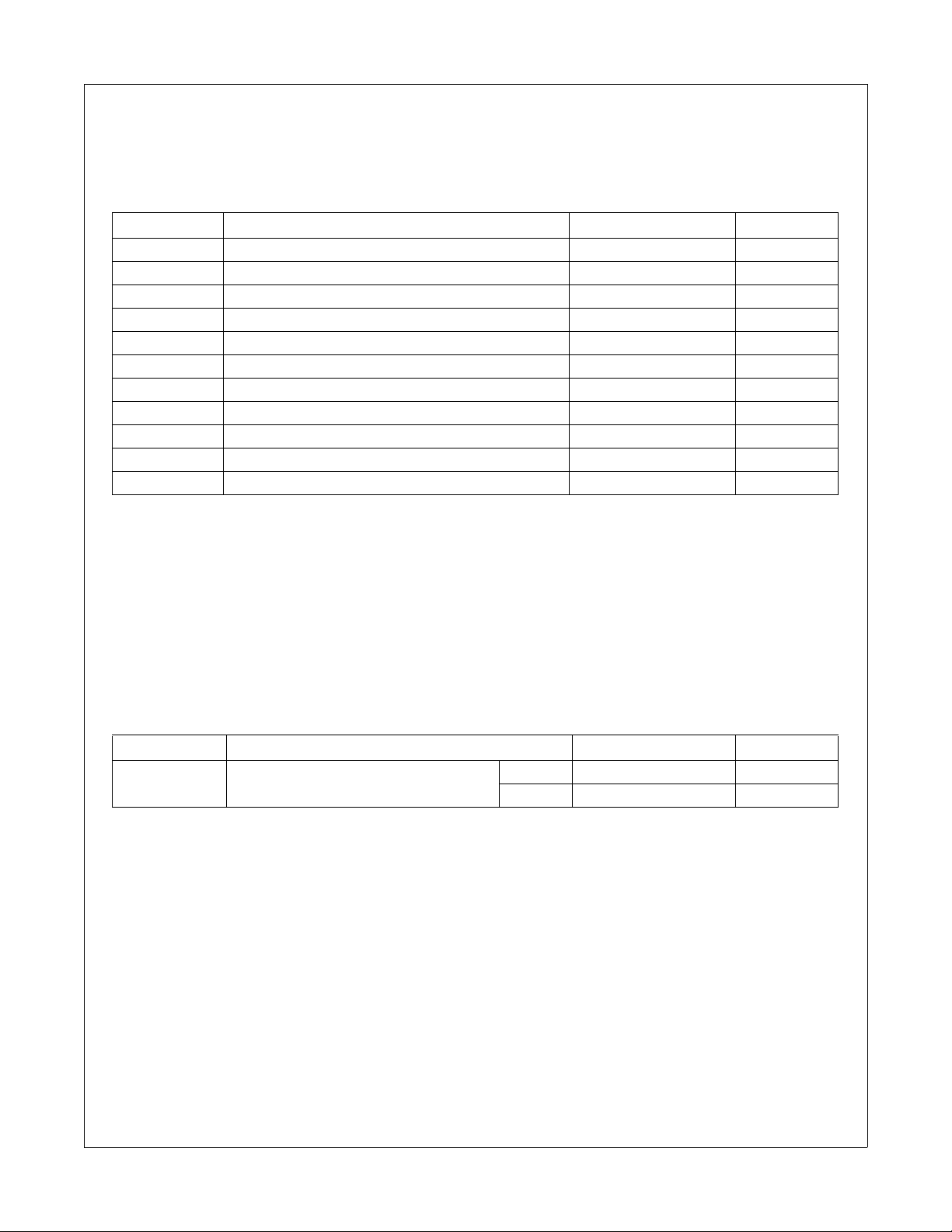
Electrical Characteristics
VCC = 14V and TA = -40°C~125°C unless otherwise specified.
Symbol Parameter Condition Min. Typ. Max. Unit
UNDER-VOLTAGE LOCKOUT SECTION
V
th(start)
V
th(stop)
HY
(uvlo)
V
SUPPLY CURRENT SECTION
I
I
CC
I
dcc
I
CC(dis)
ERROR AMPLIFIER SECTION
V
ref1
ΔV
ΔV
I
b(ea)
I
source
I
sink
V
eao(H)
V
eao(Z)
g
MAXIMUM ON-TIME SECTION
V
mot
T
on(max)
CURRENT SENSE SECTION
V
CS(limit)
I
b(cs)
t
d(cs)
Start Threshold Voltage VCC increasing 1 1 12 13 V
Stop Threshold V oltage VCC decreasing 7.5 8.5 9.5 V
UVLO Hysteresis 3.0 3.5 4.0 V
Zener Voltage ICC = 20mA 20 22 24 V
Z
Start-up Supply Current VCC = V
st
- 0.2V 40 70 µA
th(start)
Operating Supply Current Output no switching 1.5 3.0 mA
Dynamic Operating Supply Current 50kHz, Cl=1nF 2.5 4.0 mA
Operating Current at Disable V
= 0V 20 65 95 µA
inv
Voltage Feedback Input Threshold1 TA = 25°C 2.465 2.500 2.535 V
Line Regulation VCC = 14V ~ 20V 0.1 10.0 mV
ref1
Temperature Stability of V
ref2
Input Bias Current V
Output Source Current V
Output Sink Current V
Output Upper Clamp Voltage V
ref1
(2)
20 mV
= 1V ~ 4V -0.5 0.5 µA
inv
= V
inv
inv
inv
- 0.1V -12 µA
ref1
= V
+ 0.1V 12 µA
ref1
= V
- 0.1V 5.4 6.0 6.6 V
ref1
Zero Duty Cycle Output Voltage 0.9 1.0 1.1 V
Transconductance
m
Maximum On-Time Voltage R
Maximum On-Time Programming R
Current Sense Input Threshold
Voltage Limit
(2)
90 115 140 µmho
= 40.5kΩ 2.784 2.900 3.016 V
mot
= 40.5kΩ, TA = 25°C192429µs
mot
0.7 0.8 0.9 V
Input Bias Current VCS = 0V ~ 1V -1.0 -0.1 1.0 µA
Current Sense Delay to Output
(2)
dV/dt = 1V/100ns,
from 0V to 5V
350 500 ns
Note:
2. These parameters, although guaranteed by design, are not tested in production.
© 2006 Fairchild Semiconductor Corporation www.fairchildsemi.com
FAN7529 Rev. 1.0.2 5
Page 7
FAN7529 Critical Conduction Mode PFC Controller
Electrical Characteristics (Continued)
VCC = 14V and TA = -40°C~125°C unless otherwise specified.
Symbol Parameter Condition Min. Typ. Max. Unit
ZERO CURRENT DETECT SECTION
(3)
(3)
(3)
(3)
1.35 1.50 1.65 V
0.05 0.10 0.15 V
= 3mA 6.0 6.7 7.4 V
det
= -3mA 0 0.65 1.00 V
det
= 1V ~ 5V -1.0 -0.1 1.0 µA
ZCD
TA = 25°C-10mA
TA = 25°C10mA
dV/dt = -1V/100ns,
from 5V to 0V
100 200 ns
Cl = 1nF 50 100 ns
Cl = 1nF 50 100 ns
V
th(ZCD)
HY
(ZCD)
V
clamp(H)
V
clamp(L)
I
b(ZCD)
I
source(zcd)
I
sink(zcd)
t
dead
Input Voltage Threshold
Detect Hysteresis
Input High Clamp Voltage I
Input Low Clamp Voltage I
Input Bias Current V
Source Current Capability
Sink Current Capability
Maximum Delay from ZCD to Output
Turn-on
(3)
OUTPUT SECTION
V
OH
V
OL
t
t
V
O(max)
V
O(UVLO)
r
f
Output Voltage High IO = -100mA, TA = 25°C 9.2 11.0 12.8 V
Output Voltage Low IO = 200mA, TA = 25°C1.02.5V
Rising Time
Falling Time
(3)
(3)
Maximum Output Voltage VCC = 20V, IO = 100μA 11.5 13.0 14.5 V
Output Voltage with UVLO Activated VCC = 5V, IO = 100μA1V
RESTART TIMER SECTION
t
d(rst)
Restart Timer Delay 50 150 300 µs
OVER-VOLTAGE PROTECTION SECTION
OVP Threshold Voltage TA = 25°C 2.620 2.675 2.730 V
OVP Hysteresis TA = 25°C 0.120 0.175 0.230 V
HY
V
ovp
(ovp)
ENABLE SECTION
V
HY
th(en)
(en)
Enable Threshold Voltage 0.40 0.45 0.50 V
Enable Hysteresis 0.05 0.10 0.15 V
Note:
3. These parameters, although guaranteed by design, are not tested in production.
© 2006 Fairchild Semiconductor Corporation www.fairchildsemi.com
FAN7529 Rev. 1.0.2 6
Page 8

Typical Characteristics
FAN7529 Critical Conduction Mode PFC Controller
13.0
12.5
[V]
12.0
th(start)
V
11.5
11.0
-60 -40 -20 0 20 40 60 80 100 120 140
Temperature [°C]
9.5
9.0
[V]
8.5
th(stop)
V
8.0
7.5
-60 -40 -20 0 20 40 60 80 100 120 140
Temperature [°C]
Figure 4. Start Threshold Voltage vs. Temp. Figure 5. Stop Threshold Voltage vs. Temp.
[V]
HY
(UVLO)
4.00
3.75
3.50
3.25
23.0
22.5
22.0
[V]
Z
V
21.5
3.00
-60 -40 -20 0 20 40 60 80 100 120 140
Temperature [°C]
21.0
-60 -40 -20 0 20 40 60 80 100 120 140
Temperature [°C]
Figure 6. UVLO Hysteresis vs. Temp. Figure 7. Zener Voltage vs. Temp.
60
45
[μA]
st
I
30
15
-60 -40 -20 0 20 40 60 80 100 120 140
Temperature [°C]
2.4
1.6
[mA]
CC
I
0.8
0.0
-60 -40 -20 0 20 40 60 80 100 120 140
Temperature [°C]
Figure 8. Start-up Supply Current vs. Temp. Figure 9. Operating Supply Current vs. Temp.
© 2006 Fairchild Semiconductor Corporation www.fairchildsemi.com
FAN7529 Rev. 1.0.2 7
Page 9

Typical Characteristics (Continued)
FAN7529 Critical Conduction Mode PFC Controller
4
3
2
[mA]
dcc
I
1
0
-60 -40 -20 0 20 40 60 80 100 120 140
Temperature [°C]
Figure 10. Dynamic Operating Supply Current vs.
Temp.
2.52
2.50
[V]
ref1
V
2.48
90
72
54
[μA]
CC(dis)
I
36
-60 -40 -20 0 20 40 60 80 100 120 140
Temperature [°C]
Figure 11. Operating Current at Disable vs. Temp.
10.0
7.5
5.0
[mV]
ref1
ΔV
2.5
0.0
-60 -40 -20 0 20 40 60 80 100 120 140
Temperature [°C]
Figure 12. V
0.50
0.25
0.00
[μA]
b(ea)
I
-0.25
-0.50
-60 -40 -20 0 20 40 60 80 100 120 140
vs. Temp. Figure 13. ΔV
ref1
Temperature [°C]
-60 -40 -20 0 20 40 60 80 100 120 140
Temperature [°C]
vs. Temp.
ref1
-9
-12
[μA]
source
I
-15
-18
-60 -40 -20 0 20 40 60 80 100 120 140
Temperature [°C]
Figure 14. Input Bias Current vs. Temp. Figure 15. Output Source Current vs. Temp.
© 2006 Fairchild Semiconductor Corporation www.fairchildsemi.com
FAN7529 Rev. 1.0.2 8
Page 10

Typical Characteristics (Continued)
FAN7529 Critical Conduction Mode PFC Controller
18
15
12
[μA]
sink
I
9
6
-60 -40 -20 0 20 40 60 80 100 120 140
Temperature [°C]
6.6
6.3
6.0
(H) [V]
eao
V
5.7
5.4
-60 -40 -20 0 20 40 60 80 100 120 140
Temperature [°C]
Figure 16. Output Sink Current vs. Temp. Figure 17. Output Upper Clamp Voltage vs. Temp.
[V]
V
1.10
1.05
1.00
eao(Z)
0.95
3.00
2.95
2.90
[V]
mot
V
2.85
0.90
-60 -40 -20 0 20 40 60 80 100 120 140
Temperature [°C]
2.80
-60 -40 -20 0 20 40 60 80 100 120 140
Temperature [°C]
Figure 18. Zero Duty Cycle Output Voltage vs. Temp. Figure 19. Maximum On-Time Voltage vs. Temp.
27
[μs]
24
on(max)
T
21
-60 -40 -20 0 20 40 60 80 100 120 140
Temperature [°C]
0.90
0.85
[V]
0.80
cs(limit)
V
0.75
0.70
-60 -40 -20 0 20 40 60 80 100 120 140
Temperature [°C]
Figure 20. Maximum On-Time vs. Temp. Figure 21. Current Sense Input Threshold Voltage vs.
Temp.
© 2006 Fairchild Semiconductor Corporation www.fairchildsemi.com
FAN7529 Rev. 1.0.2 9
Page 11

Typical Characteristics (Continued)
FAN7529 Critical Conduction Mode PFC Controller
1.0
0.5
0.0
[μA]
b(cs)
I
-0.5
-1.0
-60 -40 -20 0 20 40 60 80 100 120 140
Temperature [°C]
7.2
6.8
[V]
6.4
clamp(H)
V
6.0
-60 -40 -20 0 20 40 60 80 100 120 140
Temperature [°C]
Figure 22. Input Bias Current vs. Temp. Figure 23. Input High Clamp Voltage vs. Temp.
[V]
V
1.00
0.75
0.50
clamp(L)
0.25
1.0
0.5
0.0
[μA]
b(zcd)
I
-0.5
0.00
-60 -40 -20 0 20 40 60 80 100 120 140
Temperature [°C]
-1.0
-60 -40 -20 0 20 40 60 80 100 120 140
Temperature [°C]
Figure 24. Input Low Clamp Voltage vs. Temp. Figure 25. Input Bias Current vs. Temp.
14
[V]
13
O(max)
V
12
-60 -40 -20 0 2 0 40 60 80 100 120 140
Temperature [°C]
0.9
0.6
0.3
[V]
O(uvlo)
0.0
V
-0.3
-60 -40 -20 0 20 40 60 80 100 120 140
Temperature [°C]
Figure 26. Maximum Output Voltage vs. Temp. Figure 27. Output Voltage with UVLO Activated vs.
Temp.
© 2006 Fairchild Semiconductor Corporation www.fairchildsemi.com
FAN7529 Rev. 1.0.2 10
Page 12

Typical Characteristics (Continued)
FAN7529 Critical Conduction Mode PFC Controller
300
250
200
[μs]
150
d(rst)
t
100
50
-60 -40 -20 0 20 40 60 80 100 120 140
Temperature [°C]
2.73
2.70
[V]
2.67
ovp
V
2.64
-60 -40 -20 0 20 40 60 80 100 120 140
Temperature [°C]
Figure 28. Restart Delay Time vs. Temp. Figure 29. OVP Threshold Voltage vs. Temp.
[V]
(OVP)
HY
0.21
0.18
0.15
0.500
0.475
0.450
[V]
th(en)
V
0.425
0.12
-60 -40 -20 0 20 40 60 80 100 120 140
Temperature [°C]
0.400
-60 -40 -20 0 20 40 60 80 100 120 140
Temperature [°C]
Figure 30. OVP Hysteresis vs. Temp. Figure 31. Enable Threshold Voltage vs. Temp.
0.150
0.125
[V]
0.100
(en)
HY
0.075
0.050
-60 -40 -20 0 20 40 60 80 100 120 140
Temperature [°C]
Figure 32. Enable Hysteresis vs. Temp.
© 2006 Fairchild Semiconductor Corporation www.fairchildsemi.com
FAN7529 Rev. 1.0.2 11
Page 13

Applications Information
FAN7529 Critical Conduction Mode PFC Controller
1. Error Amplifier Block
The error amplifier block consists of a transconductance
amplifier, output OVP comparator, and disable comparator. For the output voltage control, a transconductance
amplifier is used instead of the conventional voltage
amplifier. The transconductance amplifier (voltage controlled current source) aids the implementation of OVP
and disable function. The output current of the ampl ifier
changes according to the voltage difference of the inverting and non-inverting input of the amplifier. The output
voltage of the amplifier is compared with the internal
ramp signal to generate the switch turn-off signal. The
OVP comparator shuts down the output drive block when
the voltage of the INV pin is higher than 2.675V and
there is 0.175V hysteresis. The disable comparator disables the operation of the FAN7529 when the voltage of
the inverting input is lower than 0.45V and there is
100mV hysteresis. An external small signal MOSFET
can be used to disable the IC, as shown in Figure 33.
The IC operating current decreases below 65µA to
reduce power consumption if the IC is disabled.
OVP
Disable
Error Amp
2
COMP
Gm
2.675V 2.5V
0.45V 0.35V
V
(2.5V)
ref1
V
out
INV
1
Disable
Signal
below 1.4V. If the voltage goes below 1.4V, the zero current detector turns on the MOSFET. The ZCD pin is protected internally by two clamps, 6.7V-high clamp and
0.65V-low clamp. The 150µs timer generates a MOSFET
turn-on signal if the drive output has been low for more
than 150µs from the falling edge of the drive output.
Turn-on
Signal
V
in
ZCD
5
R
ZCD
6.7V
1.4V
1.5V
Zero Current
Detector
150μs
Timer
S
Q
R
FAN7529 Rev. 00
Figure 34. Zero Current Detector Block
3. Sawtooth Generator Block
The output of the error amplifier and the output of the
sawtooth generator are compared to determine the
MOSFET turn-off instance. The slope of the sawtooth is
determined by an external resistor connected to the
MOT pin. The voltage of the MOT pin is 2.9V and the
slope is proportional to the current flowing out of the
MOT pin. The internal ramp signal has a 1V offset; therefore, the drive output is shut down if the voltage of the
COMP pin is lower than 1V. The MOSFET on-time is
maximum when the COMP pin voltage is 5V. According
to the slope of the internal ramp, the maximum on-time
can be programmed. The necessary maximum on-time
depends on the boost inductor, lowest AC line voltage,
and maximum output power. The resistor value should
be designed properly.
Off Signal
Figure 33. Error Amplifier Block
FAN7529 Rev. 00
MOT
3
1V Offset
Saw Tooth
Generator
2.9V
2. Zero Current Detection Block
The zero current detector (ZCD) generates the turn-on
signal of the MOSFET when the boost inductor current
reaches zero using an auxiliary winding coupled wi th th e
inductor. If the voltage of the ZCD pin goes higher than
1.5V, the ZCD comparator waits until the voltage goes
© 2006 Fairchild Semiconductor Corporation www.fairchildsemi.com
FAN7529 Rev. 1.0.2 12
Figure 35. Sawtooth Generator Block
Error Amp
Output
FAN7529 Rev. 00
Page 14

FAN7529 Critical Conduction Mode PFC Controller
4. Over-Current Protection Block
The MOSFET current is sensed using an external sensing resistor for the over-current protection. If the CS pin
voltage is higher than 0.8V, the over-current protection
comparator generates a protection signal. An internal RC
filter is included to filter switching noise.
40k
4
CS
8pF
0.8V
Over Current Protection
Comparator
Figure 36. Over-Current Protection Block
OCP
Signal
FAN7529 Rev. 00
5. Switch Drive Block
The FAN7529 contains a single totem-pole output stage
designed for direct drive of the power MOSFET. The
drive output is capable of up to +500/-800mA peak current with a typical rise and fall time of 50ns with 1nF load.
The output voltage is clamped to 13V to protect the
MOSFET gate if the V
voltage is higher than 13V.
CC
6. Under-Voltage Lockout Block
If the VCC voltage reaches 12V, the IC’s internal blocks
are enabled and start operation. If the VCC voltage drops
below 8.5V, most of the internal blocks are di sabled to
reduce the operating current. V
higher than 8.5V under normal conditions.
voltage should be
CC
© 2006 Fairchild Semiconductor Corporation www.fairchildsemi.com
FAN7529 Rev. 1.0.2 13
Page 15

Typical Application Circuit
Application Output Power Input Voltage Output Voltage
Ballast 100W
Universal input
(85~265V
AC
Features
High efficiency (>90% at 85V
Low Total Harmonic Distortion (THD) (<10% at 265V
AC
input)
input, 25W load)
AC
Key Design Notes
R1, R2, R5, C11 should be optimized for best THD characteristic.
1. Schematic
)
400V
FAN7529 Critical Conduction Mode PFC Controller
NTC
LF1
F1
BD
C3 C4
C2
C1
V1
AC INPUT
C5
R3
C6
ZD1
R2
V
AUX
R4
C10
D1
V
OUT
CC
FAN7529
INV
COMP
1234
R8
C7
C8
R1
R5
GND
T1
C11
MOT
5678
ZCD
CS
D3
R6
PFC OUTPUT
D2
R10
Q1
C9
R9
R11
R7
FAN7529 Rev. 00
Figure 37. Schematic
© 2006 Fairchild Semiconductor Corporation www.fairchildsemi.com
FAN7529 Rev. 1.0.2 14
Page 16

2. Inductor Schematic Diagram
3. Winding Specification
4
N
Vcc
2
3
Np
5
FAN7529 Rev. 00
Figure 38. Inductor Schematic Diagram
FAN7529 Critical Conduction Mode PFC Controller
No Pin (s→f) Wire Turns Winding Method
Np 5 → 30.1
Insulation: Polyester Tape t = 0.050mm, 4 Layers
N
Vcc
2 → 40.2
Outer Insulation: Polyester Tape t = 0.050mm, 4 Layers
Air Gap: 0.6mm for each leg
φ
× 30 58 Solenoid Winding
φ
× 1 8 Solenoid Winding
4. Electrical Characteristics
Pin Specification Remarks
Inductance 3 - 5 600µH ± 10% 100kHz, 1V
5. Core & Bobbin
Core: EI 3026
Bobbin: EI3026
Ae(mm
2
): 111
© 2006 Fairchild Semiconductor Corporation www.fairchildsemi.com
FAN7529 Rev. 1.0.2 15
Page 17

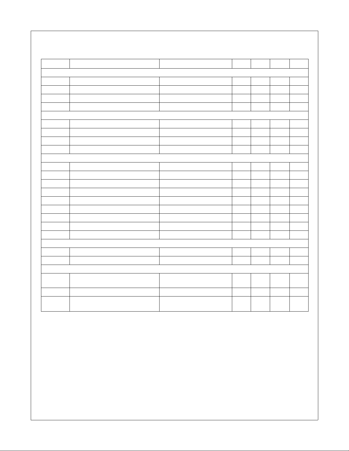
6. Demo Circuit Part List
Part Value Note Part Value Note
Fuse Inductor
F1 3A/250V T1 600µH EI3026
NTC
NTC 10D-9 MOSFET
Resistor Q1 FQPF13N50C Fairchild
R1 56kΩ 1/4W
R2 820kΩ 1/4W Diode
R3 330kΩ 1/2W D1 1N4148 Fairchild
R4 150Ω 1/2W D2 BYV26C 600V, 1A
R5 20kΩ 1/4W D3 SB140 Fairchild
R6 10Ω 1/4W ZD1 1N4746 18V
R7 0.2Ω 1/2W
R8 10kΩ 1/4W
R9 10kΩ 1/4W Bridge Diode
R10 2MΩ 1/4W BD KBL06 600V/4A
R11 12.6kΩ 1/4W
Line Filter
Capacitor LF1 40mH Wire 0.4mm
C1 150nF/275VAC Box Capacitor
C2 470nF/275VAC Box Capacitor IC
C3 2.2nF/3kV Ceramic Capacitor IC1 FAN7529 Fairchild
C4 2.2nF/3kV Ceramic Capacitor
C5 TNR
C6 47µF/25V Electrolytic Capacitor V1 471 470V
C7 47nF/50V Ceramic Capacitor
C8 220nF/50V
C9 100µF/450V Electrolytic Capacitor
C10 12nF/100V Film Capacitor
C11 56pF/50V Ceramic Capacitor
Multilayer Ceramic
Capacitor
FAN7529 Critical Conduction Mode PFC Controller
© 2006 Fairchild Semiconductor Corporation www.fairchildsemi.com
FAN7529 Rev. 1.0.2 16
Page 18

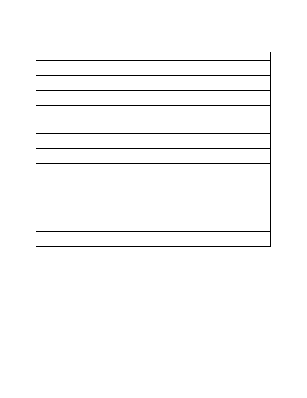
7. Layout
Power Ground
FAN7529 Critical Conduction Mode PFC Controller
Separate the power ground
and the signal ground
8. Performance Data
P
OUT
100W
75W
50W
25W
Signal Ground
Place the output voltage
sensing resistors close to IC
Figure 39. PCB Layout Considerations for FAN7529
85V
AC
PF 0.998 0.998 0.991 0.984
THD 5.1% 3.6% 5.2% 6.2%
Efficiency 90.9% 93.7% 95.6% 96%
PF 0.999 0.998 0.986 0.975
THD 4.1% 3.6% 5.0% 5.7%
Efficiency 91.6% 93.3% 94.6% 95.3%
PF 0.998 0.997 0.974 0.956
THD 4.4% 5.0% 5.7% 6.2%
Efficiency 91.3% 91.9% 92.7% 93.4%
PF 0.995 0.991 0.923 0.876
THD 7.9% 8.6% 8.3% 8.7%
Efficiency 86.4% 87.1% 87.3% 88.1%
115V
AC
230V
AC
265V
AC
© 2006 Fairchild Semiconductor Corporation www.fairchildsemi.com
FAN7529 Rev. 1.0.2 17
Page 19

Mechanical Dimensions
8-DIP
Dimensions are in millimeters (inches) unless otherwise noted..
6.40
±0.20
±0.008
0.252
0.79
0.031
()
±0.10
±0.004
±0.10
FAN7529 Critical Conduction Mode PFC Controller
±0.004
#1
#8
#4 #5
7.62
0.300
MAX
9.60
0.378
5.08
0.200
3.40
0.134
±0.20
9.20
MAX
±0.20
±0.008
±0.008
0.362
0.33
0.013
MIN
0.46
3.30
0.130
2.54
±0.30
±0.012
0.018
0.100
1.524
0.060
+0.10
0.25
–0.05
+0.004
0.010
–0.002
0~15°
Figure 40. 8-Lead Dual In-Line Package (DIP)
© 2006 Fairchild Semiconductor Corporation www.fairchildsemi.com
FAN7529 Rev. 1.0.2 18
September 1999, Rev B
8dip_dim.pdf
Page 20

Mechanical Dimensions (Continued)
8-SOP
Dimensions are in millimeters (inches) unless otherwise noted.
1.55
0.061
±0.20
±0.008
MIN
0.004~0.001
0.56
0.1~0.25
0.022
()
FAN7529 Critical Conduction Mode PFC Controller
0.006
-0.002
0.50
0.020
+
0.004
±0.20
±0.008
0.15
+
-0.05
0.10
#1
#4
6.00
0.236
3.95
0.156
0.225
±0.30
±0.20
±0.008
5.72
±0.012
#8
#5
0.071
0~8°
MAX
5.13
0.202
1.80
±0.20
4.92
MAX
±0.008
0.194
MAX0.10
MAX0.004
1.27
0.050
±0.10
0.41
±0.004
0.016
September 2001, Rev B1
sop8_dim.pdf
Figure 41. 8-Lead Small Outline Package (SOP)
© 2006 Fairchild Semiconductor Corporation www.fairchildsemi.com
FAN7529 Rev. 1.0.2 19
Page 21

TRADEMARKS
The following are registered and unregistered trademarks Fairchild Semiconductor owns or is authorized to use and is not intended to be an
exhaustive list of all such trademarks.
®
ACEx
Across the board. Around the world.¥
ActiveArray¥
Bottomless¥
Build it Now¥
CoolFET¥
CROSSVOLT¥
CTL™
Current Transfer Logic™
DOME¥
2
E
CMOS¥
EcoSPARK
®
EnSigna¥
FACT Quiet Series™
®
FACT
®
FAST
FASTr¥
FPS¥
®
FRFET
GlobalOptoisolator¥
GTO¥
i-Lo¥
ImpliedDisconnect¥
IntelliMAX¥
ISOPLANAR¥
MICROCOUPLER¥
MicroPak¥
MICROWIRE¥
Motion-SPM™
MSX¥
MSXPro¥
OCX¥
OCXPro¥
OPTOLOGIC
OPTOPLANAR
®
®
PACMAN¥
PDP-SPM™
POP¥
Power220
Power247
®
®
PowerEdge¥
PowerSaver¥
Power-SPM¥
PowerTrench
Programmable Active Droop¥
QFET
®
®
QS¥
QT Optoelectronics¥
Quiet Series¥
RapidConfigure¥
RapidConnect¥
ScalarPump¥
SMART START¥
®
SPM
STEALTH™
SuperFET¥
SuperSOT¥-3
SuperSOT¥-6
SuperSOT¥-8
SyncFET™
TCM¥
The Power Franchise
™
®
TinyBoost¥
TinyBuck¥
TinyLogic
®
TINYOPTO¥
TinyPower¥
TinyWire¥
TruTranslation¥
PSerDes¥
®
UHC
UniFET¥
VCX¥
Wire¥
HiSeC¥
FAN7529 Critical Conduction Mode PFC Controller
DISCLAIMER
FAIRCHILD SEMICONDUCTOR RESERVES THE RIGHT TO MAKE CHANGES WITHOUT FURTHER NOTICE TO ANY PRODUCTS
HEREIN TO IMPROVE RELIABILITY, FUNCTION OR DESIGN. FAIRCHILD DOES NOT ASSUME ANY LIABILITY ARISING OUT OF THE
APPLICATION OR USE OF ANY PRODUCT OR CIRCUIT DESCRIBED HEREIN; NEITHER DOES IT CONVEY ANY LICENSE UNDER
ITS PATENT RIGHTS, NOR THE RIGHTS OF OTHERS. THESE SPECIFICATIONS DO NOT EXPAND THE TERMS OF FAIRCHILD’S
WORLDWIDE TERMS AND CONDITIONS, SPECIFICALLY THE WARRANTY THEREIN, WHICH COVERS THESE PRODUCTS.
LIFE SUPPORT POLICY
FAIRCHILD’S PRODUCTS ARE NOT AUTHORIZED FOR USE AS CRITICAL COMPONENTS IN LIFE SUPPORT DEVICES OR
SYSTEMS WITHOUT THE EXPRESS WRITTEN APPROVAL OF FAIRCHILD SEMICONDUCTOR CORPORATION.
As used herein:
1. Life support devices or systems are devices or systems
which, (a) are intended for surgical implant into the body or
(b) support or sustain life, and (c) whose failure to perform
when properly used in accordance with instructions for use
2. A critical component in any component of a life support,
device, or system whose failure to perform can be
reasonably expected to cause the failure of the life support
device or system, or to affect its safety or effectiveness.
provided in the labeling, can be reasonably expected to
result in a significant injury of the user.
PRODUCT STATUS DEFINITIONS
Definition of Terms
Datasheet Identification Product Status Definition
Advance Information Formative or In Design This datasheet contains the design specifications for product
development. Specifications may change in any manner without notice.
Preliminary First Production This datasheet contains preliminary data; supplementary data will be
published at a later date. Fairchild Semiconductor reserves the right to
make changes at any time without notice to improve design.
No Identification Needed Full Production This datasheet contains final specifications. Fairchild Semiconductor
reserves the right to make changes at any time without notice to improve
design.
Obsolete Not In Production This datasheet contains specifications on a product that has been
discontinued by Fairchild Semiconductor. The datasheet is printed for
reference information only.
Rev. I26
© 2006 Fairchild Semiconductor Corporation www.fairchildsemi.com
FAN7529 Rev. 1.0.2 20
Page 22

ON Semiconductor and are trademarks of Semiconductor Components Industries, LLC dba ON Semiconductor or its subsidiaries in the United States and/or other countries.
ON Semiconductor owns the rights to a number of patents, trademarks, copyrights, trade secrets, and other intellectual property. A listing of ON Semiconductor’s product/patent
coverage may be accessed at www.onsemi.com/site/pdf/Patent−Marking.pdf
ON Semiconductor makes no warranty, representation or guarantee regarding the suitability of its products for any particular purpose, nor does ON Semiconductor assume any liability
arising out of the application or use of any product or circuit, and specifically disclaims any and all liability, including without limitation special, consequential or incidental damages.
Buyer is responsible for its products and applications using ON Semiconductor products, including compliance with all laws, regulations and safety requirements or standards,
regardless of any support or applications information provided by ON Semiconductor. “Typical” parameters which may be provided in ON Semiconductor data sheets and/or
specifications can and do vary in different applications and actual performance may vary over time. All operating parameters, including “Typicals” must be validated for each customer
application by customer’s technical experts. ON Semiconductor does not convey any license under its patent rights nor the rights of others. ON Semiconductor products are not
designed, intended, or authorized for use as a critical component in life support systems or any FDA Class 3 medical devices or medical devices with a same or similar classification
in a foreign jurisdiction or any devices intended for implantation in the human body. Should Buyer purchase or use ON Semiconductor products for any such unintended or unauthorized
application, Buyer shall indemnify and hold ON Semiconductor and its officers, employees, subsidiaries, affiliates, and distributors harmless against all claims, costs, damages, and
expenses, and reasonable attorney fees arising out of, directly or indirectly, any claim of personal injury or death associated with such unintended or unauthorized use, even if such
claim alleges that ON Semiconductor was negligent regarding the design or manufacture of the part. ON Semiconductor is an Equal Opportunity/Affirmative Action Employer. This
literature is subject to all applicable copyright laws and is not for resale in any manner.
. ON Semiconductor reserves the right to make changes without further notice to any products herein.
PUBLICATION ORDERING INFORMATION
LITERATURE FULFILLMENT:
Literature Distribution Center for ON Semiconductor
19521 E. 32nd Pkwy, Aurora, Colorado 80011 USA
Phone: 303−675−2175 or 800−344−3860 Toll Free USA/Canada
Fax: 303−675−2176 or 800−344−3867 Toll Free USA/Canada
Email: orderlit@onsemi.com
© Semiconductor Components Industries, LLC
N. American Technical Support: 800−282−9855 Toll Free
USA/Canada
Europe, Middle East and Africa Technical Support:
Phone: 421 33 790 2910
Japan Customer Focus Center
Phone: 81−3−5817−1050
www.onsemi.com
ON Semiconductor Website: www.onsemi.com
Order Literature: http://www.onsemi.com/orderlit
For additional information, please contact your local
Sales Representative
www.onsemi.com
1
Page 23

Mouser Electronics
Authorized Distributor
Click to View Pricing, Inventory, Delivery & Lifecycle Information:
Fairchild Semiconductor:
FAN7529MX FAN7529N FAN7529M
 Loading...