

Page 1
EZAIRO 7150 SL HYBRID
Wireless-Enabled Audio
Processor for Digital
Hearing Aids
Introduction
EZAIRO® 7150 SL is an open−programmable DSP−based hybrid
specifically designed for use in wirelessly connected,
high−performance hearing aids and hearing implant devices. The
Ezairo 7150 SL hybrid includes the Ezairo 7100 System−on−Chip
(SoC) with its high−precision quad−core architecture that delivers 375
MIPS, without sacrificing power consumption.
The highly−integrated Ezairo 7100 includes an optimized,
dual−Harvard CFX Digital Signal Processor (DSP) core and HEAR
Configurable Accelerator signal processing engine. It also features an
®
Arm
Cortex®−M3 Processor Subsystem that supports various types
of protocols for wireless communication. This block combines an
open−programmable controller with hardware accelerators for audio
coding and error correction support.
Ezairo 7100 also includes a programmable Filter Engine that
enables time domain filtering and supports an ultra−low−delay audio
path. When combined with non−volatile memory and wireless
transceivers, Ezairo 7100 forms a complete hardware platform.
The Ezairo 7150 SL hybrid includes the nRF51822 wireless
transceiver from Nordic Semiconductor. The nRF51822 is a powerful,
highly flexible multi−protocol SoC ideally suited for Bluetooth
Energy (BLE) and 2.4 GHz ultra−low−power wireless applications.
Ezairo 7150 SL also contains 2 Mb EEPROM storage and the
necessary passive components to directly interface with the
transducers required in a hearing aid.
®
Low
www.onsemi.com
SIP49
EZAIRO
CASE 127DQ
MARKING DIAGRAM
E7150−102
XXXXXX
(Top View)
E7150−102 = Specific Device Code
XXXXXX = Work Order Number
ORDERING INFORMATION
Device Package Shipping
E7150−102A49−AG SIP49
(Pb−Free)
†
250 / Tape &
Reel
© Semiconductor Components Industries, LLC, 2017
December, 2017 − Rev. 5
†For information on tape and reel specifications,
including part orientation and tape sizes, please
refer to our Tape and Reel Packaging Specification
Brochure, BRD8011/D.
1 Publication Order Number:
E7150/D
Page 2

EZAIRO 7150 SL HYBRID
Key Features
• Programmable Flexibility: the open−programmable
DSP−based system can be customized to the specific
signal processing needs of manufacturers. Algorithms
and features can be modified or completely new
concepts implemented without having to modify the
chip.
• Fully Integrated Hybrid: includes the Ezairo 7100
SoC, nRF51822 radio IC, 2 Mb EEPROM storage, and
the necessary passive components to directly interface
with the transducers required in a hearing aid.
• Quad−core Architecture: includes a CFX DSP, a
HEAR Configurable Accelerator, an ARM Cortex−M3
Processor Subsystem, and a programmable Filter
Engine. The system also includes an efficient
Input/Output Controller (IOC), system memories, input
and output stages, along with a full complement of
peripherals and interfaces.
• CFX DSP: a highly cycle−efficient, programmable
core that uses a 24−bit fixed−point, dual−MAC,
dual−Harvard architecture.
• HEAR Configurable Accelerator: a highly optimized
signal processing engine designed to perform common
signal processing operations and complex standard
filterbanks.
• ARM Cortex−M3 Processor Subsystem: a complete
subsystem that supports efficient data transfer to and
from the wireless transceiver or multiple transceivers.
The subsystem includes hardwired CODECS (G.722,
CVSD) and Error Correction support (Reed−Solomon,
Hamming), as well as a fully programmable ARM
Cortex−M3 processor and dedicated interfaces.
• Programmable Filter Engine: a filtering system that
allows applying a various range of pre− or post−
processing filtering, such as IIR, FIR and biquad filters.
• Configurable System Clock Speeds: 1.28 MHz, 1.92
MHz, 2.56 MHz, 3.84 MHz, 5.12 MHz, 6.4 MHz, 7.68
MHz, 8.96 MHz, 9.60 MHz, 10.24 Mhz (default clock
calibration), 12.80MHz and 15.36MHz to optimize the
computing performance versus power consumption
ratio. The calibration entires for these 12 clock speeds
are stored in the manufacturing area of the EEPROM.
• Ultra−low Delay: programmable Filter Engine
supports an ultra−low−delay audio path of 0.044 ms (44
ms) for superior performance of features such as
occlusion management.
• Ultra−high Fidelity: 85 dB system dynamic range with
up to 110 dB input signal dynamic range,
exceptionally−low system noise and low group delay.
• Ultra−low Power Consumption: <0.7 mA @ 10.24
MHz system clock (executing a tight MAC−loop in the
CFX DSP core plus a typical hearing aid filterbank on
the HEAR Configurable Accelerator).
• High Output Level: output levels of ~139 dB SPL
possible with low impedance receiver (measured using
IEC 711 coupler).
• Diverse Memory Architecture: a total of 40 kwords of
program memory and 44 kwords of data memory,
shared between the four cores included on the Ezairo
7100 chip.
• Data Security: sensitive program data can be
encrypted for storage in EEPROM to prevent
unauthorized parties from gaining access to proprietary
algorithm intellectual property.
• Signal Detection Unit: ultra−low−power detection
system for signals on any analog inputs.
• High Speed Communication Interface: fast
2
C−based interface for quick download, debugging and
I
general communication.
• Highly Configurable Interfaces: two PCM interfaces,
2
C interfaces, two SPI interfaces, a UART
two I
interface as well as multiple GPIOs can be used to
stream configuration, control or signal data into and out
of the Ezairo 7150 SL hybrid.
• On−chip PLL: support for communication
synchronization with wireless transceiver.
• Glueless MMI: link to various analog and digital user
interfaces such as analog or digital volume control
potentiometers, push buttons for program selection and
microphone/telecoil switching.
• Fitting Support: support for Microcard, HI−PRO 2,
HI−PRO USB, QuickCom, and NOAHlinkt, including
NOAHlink’s audio streaming feature.
• Development Tools: The Ezairo Preconfigured Suite
provides a software application to fine−tune and
customize the firmware bundle pre−loaded on Ezairo
7150 SL. A cross−platform Software Development Kit
(SDK) to develop fitting software and wireless
applications is also provided. To program the Ezairo
7150 SL with your own firmware, the Ezairo 7100
Evaluation and Development Kit (EDK) includes
optimized hardware, programming interface, and a
comprehensive Integrated Development Environment
(IDE).
• These Devices are Pb−Free, Halogen Free/BFR Free
and are RoHS Compliant
.
www.onsemi.com
2
Page 3
EZAIRO 7150 SL HYBRID
Table 1. ABSOLUTE MAXIMUM RATINGS
Symbol Parameter Min Max Unit
VBAT Power supply voltage 2 V
VBATOD Output drivers power supply voltage 2 V
VDDO
1,2,3
Vin Voltage at any input pin GNDC−0.3 VDDO + 0.3 V
DGND, AGND, HGND Digital and Analog Grounds 0 − V
T functional Functional temperature range (Note 2) −40 85 °C
T operational Operational temperature range (Note 2) 0 50 °C
T storage Storage temperature range −40 85 °C
Caution: Class 2 ESD Sensitivity, JESD22*A114*B (2000 V)
Stresses exceeding those listed in the Maximum Ratings table may damage the device. If any of these limits are exceeded, device functionality
should not be assumed, damage may occur and reliability may be affected.
1. In some applications, VDDO can be higher than 2.1 V (maximum 3.3 V). In such cases, the user must set the VDDM voltage at a minimum
of 1.1 V
2. Electrical Specification may exceed listed tolerances when out of the temperature range 0 to 50°C
The tests were performed at 20°C with a 1.25 V supply voltage and 4.7 W series resistor to simulate a nominal hearing aid
battery. The system clock (SYS_CLK) was set to 5.12 MHz and an audio input sampling frequency of 16 kHz was used.
Parameters marked as screened are tested on each chip.
I/O supply voltage 3.3 (Note 1) V
Electrical Performance Specifications
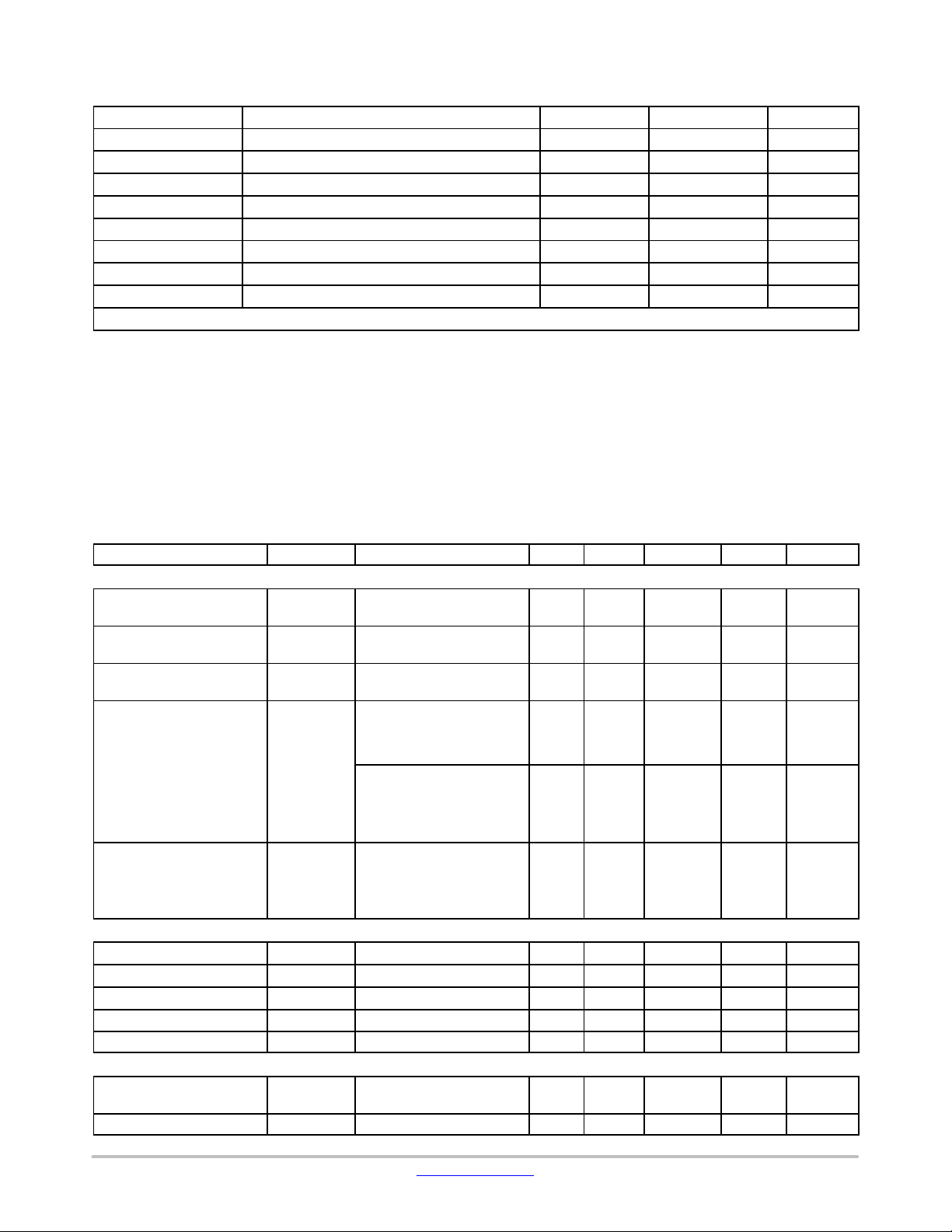
Table 2. ELECTRICAL SPECIFICATIONS
Description Symbol Conditions Min Typ Max Units Screened
OVERALL
Supply Voltage VBAT Supply voltage measured
at the VBAT pin
I/O Supply Voltage
Domain 1,2
I/O Supply Voltage
Domain 3
Current consumption I
VDDO
VDDO
VBAT
1,2
3
Filterbank: 30% load CFX:
100% load SYS_CLK:
10.24 MHz. No activity on
the nRF51822
Ezairo Pre Suite firmware
bundle running at 10.24
MHz, all algorithms active,
no transducers connected,
no activity on the nRF51822.
Stand by current I
stb
Using ON’s macro to put
the Ezairo 7100 DSP in
Standby Mode. Include
30 mA coming from the
nRF51822 standby current.
VREG
Regulated voltage output
Regulator PSRR VREG
Load current I
Load regulation LOAD
Line regulation LINE
VREG
PSRR
LOAD
REG
REG
I
=100 mA
load
1 kHz, VBAT=1.25 V 76 80 − dB
5 mA < Iload < 2 mA
Iload = 1 mA − 2 5 mV/V
VDDA
Output voltage trimming
range
Regulator PSRR VDDA
VDDA Control register configured,
typical values
PSRR
1 kHz, VBAT=1.25V 40 50 − dB
1.05 1.25 2.0 V
1.05 − 3.3 V
1.05 − Vbat V
− 700 −
− 1090 −
70 150
0.96 0.97 0.98 V
− − 2 mA
− 4 10 mV/mA
1.8 2.0 2.1 V
mA
mA
mA
n
n
www.onsemi.com
3
Page 4

EZAIRO 7150 SL HYBRID
Table 2. ELECTRICAL SPECIFICATIONS
Description ScreenedUnitsMaxTypMinConditionsSymbol
VDDA
Load current
Load regulation LOAD
Line regulation LINE
I
LOAD
REG
REG
VBAT = 1.2 V; 100 _A <
Iload < 1 mA
1.2 V < VBAT < 1.86 V;
Iload = 100 uA
VDBL
Output voltage trimming
range
Regulator PSRR VDBL
Load current I
Load regulation LOAD
Line regulation LINE
VDBL Control register configured,
typical values, unloaded
PSRR
LOAD
REG
REG
1 kHz, VBAT=1.25 V 30 40 − dB
ITRIM (A_CP_VDBL_CTRL)
= 0x7
VBAT = 1.2 V; 100 mA <
Iload < 3 mA
VBAT > 1.2 V; Iload = 100 mA
VDDC
Digital supply output voltage trimming range
VDDC output level adjustment
Regulator PSRR VDDC
Load current I
Load regulation LOAD
Line regulation LINE
VDDC Control register configured,
typical values, unloaded
VDDC
STEP
PSRR
LOAD
REG
REG
1 kHz, VBAT=1.25 V 25 30 − dB
Delivered by LDO − − 5 mA
VDDM
Memory supply output voltage trimming range
VDDM output level adjustment
Regulator PSRR VDDM
Load current I
Load regulation LOAD
Line regulation LINE
VDDM Control register configured,
typical values, unloaded
VDDM
STEP
PSRR
LOAD
REG
REG
1 kHz, VBAT=1.25 V 25 30 − dB
Delivered by LDO − − 5 mA
POWER−ON−RESET
POR startup voltage
VBAT
STARTUP
POR shutdown voltage VBAT
SHUTDOWN
INPUT STAGE
Analog input voltage range V
IN
Preamplifier gain PAG 3 dB steps 0 − 36 dB
Preamplifier gain accuracy PAG acc 1 kHz, PAG from 0 to 36 dB −1.5 0 1.5 dB
Input impedance R
IN
Non−0dB preamplifier gains 370 500 725
− − 1 mA
− 4 10 mV/mA
− 6 20 mV/V
1.6 2.0 2.2 V
− − 15 mA
− 4 10 mV/mA
− 6 20 mV/V
0.72 −
1.32 V
(Note 3)
1.5 2.5 3 mV
− 5 10 mV/mA
− 6 12 mV/V
0.82 −
1.32 V
(Note 4)
1.5 2.5 3 mV
− 5 10 mV/mA
− 6 12 mV/V
− 0.9 − V
− 0.88 − V
0 − 2 V
n
n
n
n
n
n (Note 5)
n (Note 6)
n
n
kW n
www.onsemi.com
4
Page 5
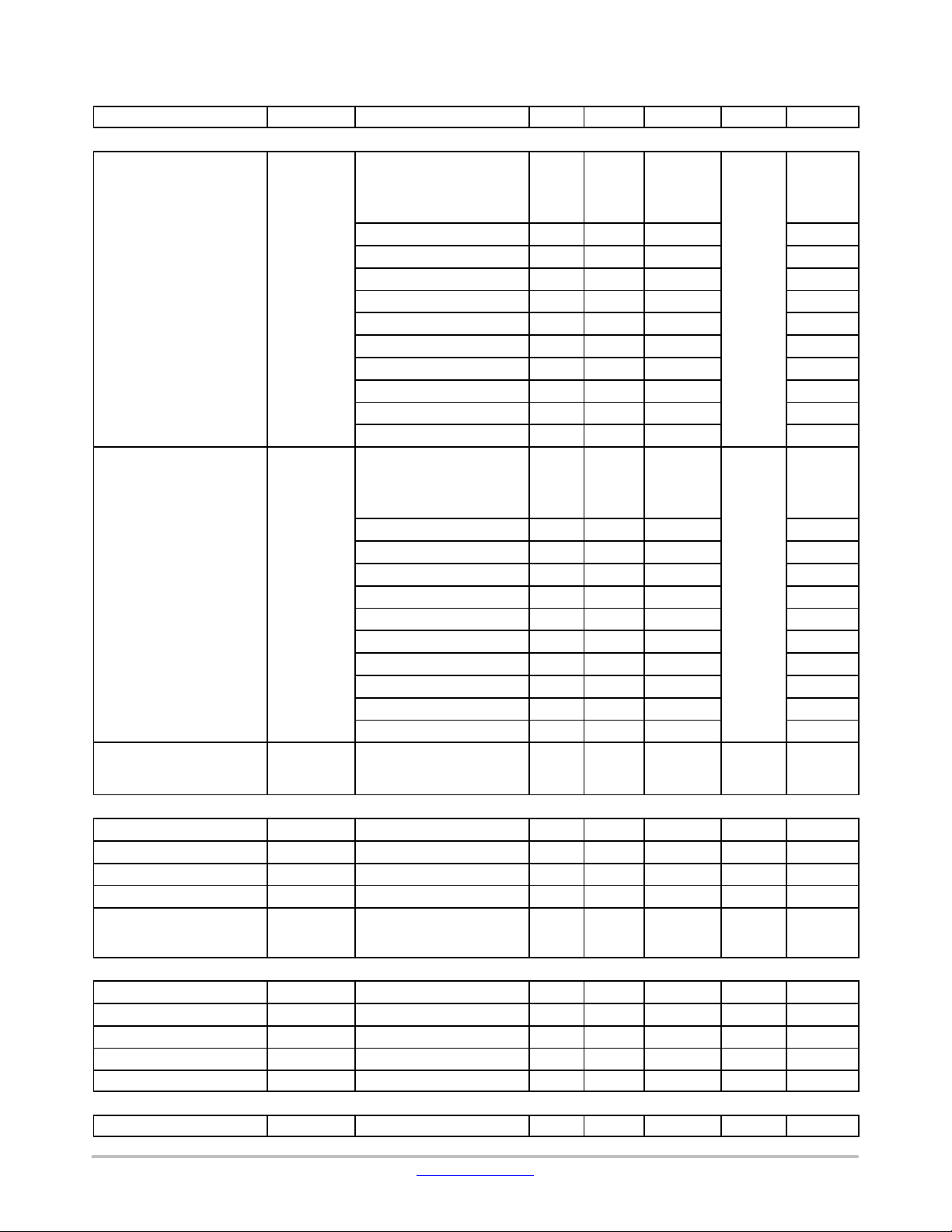
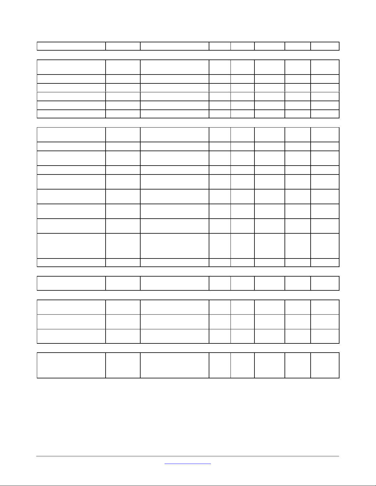
Table 2. ELECTRICAL SPECIFICATIONS
Description ScreenedUnitsMaxTypMinConditionsSymbol
INPUT STAGE
Input referred noise
Input Dynamic Range
(Note 7)
Input peak THD+N IN
OUTPUT DRIVER
Maximum peak current I
Output impedance R
Output impedance R
Output dynamic range DO
Output THD+N DO
10−BIT LOW−SPEED A/D
Input voltage range LSAD
INL LSAD
DNL LSAD
Sampling frequency LSAD
Channel sampling frequency LSAD
SIGNAL DETECTION UNIT
Preamplifier gain SDU
IN
IRN
IN
DR
THD+N
DO
DO
DO
THDN
RANGE
CH_SF
DR
INL
DNL
SF
PAG
EZAIRO 7150 SL HYBRID
AIR connected to AGND
Unweighted, 100 Hz to
10 kHz BW
Preamplifier settings:
0 dB 53 −
12 dB 13 −
15 dB 9 −
18 dB 6.6 10.6
21 dB 4.9 −
24 dB 4.3 −
27 dB 3.7 −
30 dB 3.2 −
33 dB 3.2 −
36 dB 3.2 −
AIR connected to AGND
Unweighted, 100 Hz to 10
kHz BW
Preamplifier settings:
0 dB − 86
12 dB − 86
15 dB − 86
18 dB 81 86
21 dB − 85
24 dB − 82
27 dB − 82
30 dB − 80
33 dB − 77
36 dB − 74
Any preamplifier gain
− − −68 dB
−10 dBFS signal at preamp
output, 1kHz.
High Power mode − − 25 mA
Normal mode, Iload = 1 mA − 4.5 5.5
High Power mode − 2.5 4
Normal mode, VBAT=1.25V 90 − − dB
At 1 kHz, −6 dBFS, 8 kHz
− −78 −76 dB
bandwidth, VBAT=1.25V,
normal mode
Peak input voltage 0 − 1.94 V
From GND to 2*VREG −4 − +4 LSB
From GND to 2*VREG −2 − +2 LSB
All channels sequentially − 12.8 − kHz
− 1.6 − kHz
3 dB steps 0 − 36 dB
mVrms
dB
W
W
n
n
n
n
n
www.onsemi.com
5
Page 6
EZAIRO 7150 SL HYBRID
Table 2. ELECTRICAL SPECIFICATIONS
Description ScreenedUnitsMaxTypMinConditionsSymbol
SIGNAL DETECTION UNIT
Equivalent IRN
SDU
IRN
Input impedance SDU
Low Pass Filter Bandwidth SDU
ADC input signal range SDU
ADC resolution SDU
ADC sampling frequency SDU
LPF
RANGE
RES
SF
DIGITAL
Voltage level for high input
Voltage level for low input V
Voltage level for high output V
Voltage level for low output V
Oscillator frequency trim-
V
IH
IL
OH
OL
SYS_CLK −1 − +1 %
ming precision
Oscillator frequency stabili-
SYS_CLK Over temperature range of
ty over temperature
Recommended working
SYS_CLK For recommended VDDC
frequency
Oscillator period jitter RMS at System clock: 1.28
PLL lock time For an input phase error
PLL tracking range −2 − 2 %
LOW DELAY PATH
Group Delay Using the low delay path of
EEPROM
EEPROM burn cycles Per EA2M datasheet 1’000
Current consumption –
writing to EEPROM
Current consumption –
read from EEPROM
I
W
I
R
RADIO ANTENNA MATCHING NETWORK
Optimum differential impedance at 2.4 Ghz seen
ZANT1,
ANT2
into the matching network
from pin ANT1 and ANT2
Product parametric performance is indicated in the Electrical Characteristics for the listed test conditions, unless otherwise noted. Product
performance may not be indicated by the Electrical Characteristics if operated under different conditions.
3. Recommended VDDC values depend on the system clock (SYS_CLK) frequency. Table 3 gives the recommended VDDC values for different
system clocks.
4. The minimum VDDM value required for proper system functioning is 0.90V
5. Pass fail test with 0.855 V and 0.945 V
6. Pass fail test with 0.835 V and 0.925 V
7. The audio performance might be slightly impacted when the nRF51822 radio is turned on. Degradation depends on the duty cycle of the
communication, on the external components,...
Non−weighted, 30 dB gain,
− − 20
100 Hz − 10 kHz
R
370 500 725 kOhm
50 kHz
Referred to VREG −1 +1 V
12 bits
At slow_clock = 1.28 MHz 1 64 kHz
VDD
− − V
O*0.8
− − VDDO*0.2 V
2 mA source current VDD
− V
O*0.8
2 mA sink current − − VDDO*0.2 V
−1.5 − +1.5 %
0 to 50°C
1.28 − 15.36 MHz
and VDDM
− − 400 ps
MHz, before multiplication
− − 10 ms
<2%, input reference clock
of 128 kHz, output clock of
2.56MHz
− 44 −
the Filter Engine
− − Cycles
000
0.7 mA
0.4 mA
− 12.6 +
j106
mVrms n
n
n
n
n
n
n
n
ms
−
W
www.onsemi.com
6
Page 7

EZAIRO 7150 SL HYBRID
Table 3. RECOMMENDED MINIMUM VDDC LEVEL
Operating Frequency (MHz) Minimum VDDC Voltage (V)
1.28 to 5.12 0.73
5.13 to 10.24 0.82 (Note 8)
10.25 to 12.8 0.85
12.81 to 15.36 0.88 (Note 9)
8. The default VDDC calibration entry , stored in the manufacturing area of the EEPROM at address 0x0064, should be used for operation at
0.82V.
9. An alternate VDDC calibration entry, stored in the manufacturing area of the EEPROM at address 0x00E8, should be used for operation at
0.88V.
Packaging and Manufacturing
• Ultra−Miniature Form Factor: suitable for all hearing
aid styles including CIC, ITE, RITE, BTE, and
• RoHS compliant: the Ezairo 7150 SL hybrid complies
with the RoHS directive.
mini−BTE.
• Reflowable: the Ezairo 7150 SL hybrid is reflowable
onto FR4 and other substrates.
System Diagram
Figure 1 is a simplified diagram of the hybrid system that shows the major internal functional blocks and possible external
peripherals.
Figure 1. Ezairo 7150 SL Hybrid System Diagram
www.onsemi.com
7
Page 8

EZAIRO 7150 SL HYBRID
Ezairo 7150 SL Hybrid Interface Specifications
A total of 49 pads are present on the Ezairo 7150 SL hybrid. These pads are the interfaces between the hybrid and the other
components in the hearing aid. They are listed in Table 4 along with the internal connections.
Table 4. PAD DESCRIPTION
Ball Number Hybrid Pad Name Hybrid Pad Descritpion
A1 DGND Digital ground
A2 HGND Output Driver Ground
A3 CAP0 Charge pump capacitor 0
A4 RCVR0N Output Driver: Receiver Output 0 Negative
A5 RCVR1N Output Driver: Receiver Output 1 Negative
A6 DIO24 Digital Input Output 24
A7 DIO23 Digital Input Output 23
A8 SDA Debug Port Data
A9 SCL Debug Port Clock
B1 VBAT Power Supply
B2 RCVRBAT Output Stage Power Supply
B3 CAP1 Charge pump capacitor 1
B4 RCVR0P Output Driver: Receiver Output 0 Positive
B5 RCVR1P Output Driver: Receiver Output 1 Positive
B6 DIO29 Digital Input Output 29
B7 DIO22 Digital Input Output 22
B8 DIO21 Digital Input Output 21
B9 VDDO3 IO Power Supply for DIO20 to DIO29
B10 VDDO2 IO Power Supply for DIO10 to DIO19
C1 VREG Regulated voltage output
C2 AGND Analog Ground
C3 DIO5 Digital Input Output 5
C4 DIO9 Digital Input Output 9
C5 VDBL Regulated doubled voltage output
C6 RF_SWDIO nRF51822: chip reset (active low) / hardware debug and flash programming I/O.
C7 EXTCLK External clock input / Internal
C8 DIO20 Digital Input Output 20
C9 RF_SWDCLK nRF51822: Hardware debug and flash programming I/O.
C10 RF_VDD nRF51822: Power supply.
D1 AI3 Analog Input 3: Direct Analog Input
D2 AI1 Analog Input 1: Microphone or Telecoil Input
D3 GND_MIC Input Transducer Ground
D4 DIO8 Digital Input Output 8
D5 RFGND RF Ground
D6 RFGND RF Ground
D7 RFGND RF Ground
D8 RFGND RF Ground
D9 RFGND RF Ground
D10 RF_AVDD nRF51822: Analog power supply (Radio).
E1 AI2 Analog Input 2: Microphone or Telecoil Input
E2 AI0 Analog Input 0: Microphone or Telecoil Input
E3 VMIC Regulated voltage for microphone
E4 DIO6 Digital Input Output 6
E5 RFGND RF Ground
E6 ANT1 nRF51822: Differential antenna connection (TX and RX).
E7 ANT2 nRF51822: Differential antenna connection (TX and RX).
E8 RFGND RF Ground
E9 VDDPA nRF51822: Power supply output (+1.6 V) for on−chip RF power amp.
E10 RFGND RF Ground
www.onsemi.com
8
Page 9

EZAIRO 7150 SL HYBRID
Figure 2. Ezairo 7150 SL Hybrid Schematics
www.onsemi.com
9
Page 10

EZAIRO 7150 SL HYBRID
Figure 3. Ezairo 7150 SL Hybrid Schematics
www.onsemi.com
10
Page 11

EZAIRO 7150 SL HYBRID
Connection Diagram
The following connections are typical when Ezairo 7150 SL is used in a hearing aid application. For details on the connections
required by the preconfigured firmware bundle refer to AND9651/D.
Figure 4. Connection Diagram
NOTE: For the purposes of wireless certification, it is recommended that the following signals are accessible or brought out
to solderable test points: VBAT, GND, VDBL, DIO6, DIO8.
www.onsemi.com
11
Page 12

EZAIRO 7150 SL HYBRID
EZAIRO 7100 ARCHITECTURE OVERVIEW
The Ezairo 7100 system is an asymmetric quad−core
architecture, mixed−signal system−on−chip designed
specifically for audio processing. It centers around four
processing cores: the CFX Digital Signal Processor (DSP),
the HEAR Configurable Accelerator, the ARM Cortex−M3
Processor Subsystem, and the Filter Engine.
CFX DSP Core
The CFX DSP core is used to configure the system and the
other cores, and it coordinates the flow of signal data
progressing through the system. The CFX DSP can also be
used for custom signal processing applications that can’t be
handled by the HEAR or the Filter Engine.
The CFX DSP is a user−programmable general−purpose
DSP core that uses a 24−bit fixed−point, dual−MAC,
dual−Harvard architecture. It is able to perform two MACs,
two memory operations and two pointer updates per cycle,
making it well−suited to computationally intensive
algorithms.
The CFX features:
• Dual−MAC 24−bit load−store DSP core
• Four 56−bit accumulators
• Four 24−bit input registers
• Support for hardware loops nested up to four deep
• Combined XY memory space (48 bits wide)
• Dual address generator units
• A wide range of addressing modes:
♦ Direct
♦ Indirect with post−modification
♦ Modulo addressing
♦ Bit reverse
For further information on the usage of the CFX DSP,
please refer to the Hardware Reference Manual and to the
CFX DSP Ar chitecture Manual, available in the Ezairo 7100
Evaluation and Development Kit (EDK).
HEAR Configurable Accelerator
The HEAR coprocessor is designed to perform both
common signal processing operations and complex standard
filterbanks such as the WOLA filterbank, reducing the load
on the CFX DSP core.
The HEAR Configurable Accelerator is a highly
optimized signal processing engine that is configured
through the CFX. It offers high speed, high flexibility and
high performance, while maintaining low power
consumption. For added computing precision, the HEAR
supports block floating point processing. Configuration of
the HEAR is performed using the HEAR configuration tool
(HCT). For further information on the usage of the HEAR,
please refer to the HEAR Configurable Accelerator
Reference Manual, available in the Ezairo 7100 EDK.
The HEAR is optimized for advanced hearing aid
algorithms including but not limited to the following:
• Dynamic range compression
• Directional processing
• Feedback cancellation
• Noise reduction
To execute these and other algorithms efficiently, the HEAR
excels at the following:
• Processing using a weighted overlap add (WOLA)
filterbank
• Time domain filtering
• Subband filtering
• Attack/release filtering
• Vector addition/subtraction/multiplication
• Signal statistics (such as average, variance and
correlation)
ARM Cortex−M3 Processor Subsystem
The ARM Cortex−M3 Processor Subsystem provides
support for d a t a t r a n s f e r t o a n d f r o m t h e w i r e l e s s t r a n s c e i v e r.
The subsystem includes hardwired CODECS (G.722,
CVSD), Error Correction support (Reed−Solomon,
Hamming), interfaces (SPI, I
open−programmable ARM Cortex−M3 processor.
ARM Cortex−M3 Processor
The ARM Cortex−M3 processor is a low−power
processor that features low gate count, low interrupt latency,
and low−cost debugging. It is intended for deeply embedded
applications that require fast interrupt response features.
GNU tools provide build and link support C programs that
run on the ARM Cortex−M3 processor.
Filter Engine
The Filter Engine is a core that provides low−delay path
and basic filtering capabilities for the Ezairo 7100 system.
The Filter Engine can implement filters (either FIR or IIR)
with a total of up to 160 coefficients. FIR filters are
implemented using a direct−form structure. IIR filters are
implemented with a cascade of second−order sections
(biquads), each implemented as a direct−form I filter.
The Filter Engine is programmable, but does not include
direct debugging access. The CFX can monitor the Filter
Engine state through control and configuration registers on
the program memory bus.
Digital Input/Output (DIO) Pads
A total of 10 DIOs are available on the Ezairo 7150 SL
hybrid. These pads can all be configured for a variety of
digital input and output modes or as LSADs. The user can
configure DIOs signal to be, for example:
2
C, PCM, GPIOs), as well as an
• CFX PCM interface
• CFX UART interface
• CFX SPI interface
• LSAD input
• GPIOs data for the CFX
www.onsemi.com
12
Page 13

EZAIRO 7150 SL HYBRID
• ARM Cortex−M3 processor PCM interface
• ARM Cortex−M3 processor SPI interface
• ARM Cortex−M3 processor I
2
C interface
• ARM Cortex−M3 processor GPIOs
More details on the Ezairo 7150 SL external interfaces can
be found in the Ezairo 7100 Hardware Reference Manual,
available in the Ezairo 7100 EDK.
The 10 DIOs are split into two power domains as follow:
• DIO5, DIO6, DIO8 and DIO9 are at the VDBL voltage.
• DIO20, DIO21. DIO22, DIO23, DIO24 and DIO29 are
at a IO supply defined by VDDO3
The SDA and SCL pads are on the VDDO3 power domain.
Debug Ports
The CFX’s I2C interfaces share the same I2C bus within
the Ezairo 7100 chip with two other I
Pre Suite Firmware Bundle
The default firmware image loaded in the EEPROM of
Ezairo 7150 SL comprises a realtime framework and suite
of advanced sound processing algorithms ideal for
high−end, full featured hearing aids (available under NDA).
For additional details about the Pre Suite firmware bundle
for Ezairo 7150 SL refer to AND9651/D.
The default application leaves the debug port of Ezairo
7150 SL in Restricted Mode. It is possible to erase the
default application and replace it with your own firmware
image provided you first use the Jump ROM functions
”Wipe” and ”Unlock” to place the device in Unrestricted
2
C interfaces:
Default Firmware Image on Ezairo 7150 SL
CFX Debug Port I
2
C
The CFX debug port I2C interface is a hardware debugger
for the Ezairo 7100 system that is always enabled regardless
2
of the configuration of the general−purpose I
C interface.
The debug port implements the debug port protocol
command set and is tightly coupled with the CFX DSP and
the memory components attached to the CFX. The default
address is 0x60.
ARM Cortex−M3 Debug Port I
2
C
The ARM Cortex−M3 debug port I2C interface is a
hardware debugger for the Ezairo 7100 system that is always
enabled regardless of the configuration of the
general−purpose I
2
C interface. The debug port implements
an ARM Cortex−M3 processor debug port protocol
command set that is tightly coupled with the ARM
Cortex−M3 processor and the memory components attached
to this core. The default address is 0x40.
Mode. Refer to the Communication Protocols Manual for
Ezairo 7100 for more information.
Conditions
SYS_CLK = 10.24 MHz
Firmware: Simple FIFO copy application
Gain normalized to 0 dB at 1 kHz
Measurements taken electrically with a two−pole RC filter
on the output with a cutoff frequency (−3 dB point) of 8 kHz.
From 2 kHz to 8 kHz, the roll−off is due to the RC filter.
www.onsemi.com
13
Page 14

Frequency Response Graph
EZAIRO 7150 SL HYBRID
Figure 5. Frequency Response Graph
Chip Identification
System identification is used to identify different system
components. This information can be retrieved using the
Promirat Serial Platform from TotalPhase, Inc. or the
Communications Accelerator Adaptor (CAA) with the
protocol software provided by ON Semiconductor. For the
Ezairo 7100 chip, the key identifier components and values
are as follows:
• Chip Family: 0x06
• Chip Version:0x01
• Chip Revision: 0x0200
The hybrid ID can be found in the manufacturing area of the
EEPROM at address 0x00F1 to 0x00F2 (2 bytes => 16 bits)
• Hybrid ID: 0x0321
Solder Information
The Ezairo 7150 SL hybrid is constructed with all RoHS
compliant material and should therefore be reflowed
accordingly. The bump metallization is SAC305 (Sn96.5/
Ag3.0/Cu0.5).
This hybrid device is Moisture Sensitive Class MSL4 and
must be stored and handled accordingly. Re−flow according
to IPC/JEDEC standard J−STD−020C, Joint Industry
Standard: Moisture/Re−flow Sensitivity Classification for
Nonhermetic Solid State Surface Mount Devices. The
typical re−flow profile is shown in Figure 6.
For soldering guidelines, please refer to the Soldering and
Mounting Techniques Reference Manual (SOLDERRM/D).
www.onsemi.com
14
Page 15

EZAIRO 7150 SL HYBRID
Figure 6. Typical Reflow Profile
Tape & Reel Information
Package Orientation on Tape Dimensions
Hybrid orientation in pocket is pad side down and pin 1 in upper left corner.
Figure 7. Package Orientation
www.onsemi.com
15
Page 16

EZAIRO 7150 SL HYBRID
Electrostatic Discharge (ESD) Device
CAUTION: ESD sensitive device. Permanent damage may
occur on devices subjected to high−energy electrostatic
discharges. Proper ESD precautions in handling, packaging
and testing are recommended to avoid performance
degradation or loss of functionality.
Development Tools
A full suite of comprehensive tools is available to assist
software developers from the initial concept and technology
assessment through to prototyping and product launch. For
more information on available development tools, contact
your local sales representative or authorized distributor.
Reference Design
A reference design of a wireless−enabled hearing aid
based on Ezairo 7150 SL is available. It includes source
code, design files and schematic layouts of the hearing aid
as well as a remote dongle that can be used for stereo audio
streaming. A provided sample Android phone application
demonstrates Control over BLE (CoBLE) functionality. The
reference design package is included with the purchase of
the Ezairo 7150 SL hybrid demonstrator board
(0W705001GEVK).
Company or Product Inquiries
For more information about ON Semiconductor products
or services visit our web site at http://onsemi.com
Technical Contact Information
.
dsp.support@onsemi.com
EZAIRO is a registered trademark of Semiconductor Components Industries, LLC. NOAHlink is a trademark of HIMSA A/S.
Bluetooth is a registered trademark of Bluetooth SIG, Inc. Arm and Cortex are registered trademarks of Arm Limited.
Promira is a trademark of Total Phase, Inc.
www.onsemi.com
16
Page 17

MECHANICAL CASE OUTLINE
PACKAGE DIMENSIONS
SCALE 2:1
E
PIN A1
INDICATOR
TOP VIEW
0.13 C
0.03
NOTE 3
49X
C
NOTE 3
0.05 C
b
A0.05 BC
A
B
C
D
E
123
SIDE VIEW
4
56
BOTTOM VIEW
e/2
e
7
8910
A1
SIP49 3.94x7.39
CASE 127DQ
ISSUE O
A B
D
A2
A
SEATING
C
PLANE
e
DATE 30 APR 2015
NOTES:
1. DIMENSIONING AND TOLERANCING PER
ASME Y14.5M, 1994.
2. CONTROLLING DIMENSION: MILLIMETERS.
3. DIMENSION b IS MEASURED AT THE
MAXIMUM BALL DIAMETER PARALLEL TO
DATUM C.
4. COPLANARITY APPLIES TO SPHERICAL
CROWNS OF SOLDER BALLS.
5. DATUM C, THE SEATING PLANE, IS DEFINED
BY THE SPHERICAL CROWNS OF SOLDER
BALLS.
MILLIMETERS
DIMAMIN MAX
−−−
A1
A2 −−− 1.608
b
D
E
e
1.778
0.07 0.17
0.356 0.456
3.840 4.040
7.290 7.490
0.686 BSC
RECOMMENDED
SOLDERING FOOTPRINT*
PACKAGE
OUTLINE
0.686
PITCH
A1
0.686
PITCH
DIMENSIONS: MILLIMETERS
*For additional information on our Pb−Free strategy and soldering
details, please download the ON Semiconductor Soldering and
Mounting Techniques Reference Manual, SOLDERRM/D.
49X
0.410
DOCUMENT NUMBER:
STATUS:
NEW STANDARD:
© Semiconductor Components Industries, LLC, 2002
October, 2002 − Rev. 0
DESCRIPTION:
98AON94173F
ON SEMICONDUCTOR STANDARD
SIP49 3.94X7.39
http://onsemi.com
1
Electronic versions are uncontrolled except when
accessed directly from the Document Repository. Printed
versions are uncontrolled except when stamped
“CONTROLLED COPY” in red.
Case Outline Number:
PAGE 1 OF 2
XXX
Page 18

DOCUMENT NUMBER:
:
98AON94173F
PAGE 2 OF 2
ISSUE REVISION DATE
O RELEASED FOR PRODUCTION. REQ. BY J. STEFFLER. 30 APR 2015
ON Semiconductor and are registered trademarks of Semiconductor Components Industries, LLC (SCILLC). SCILLC reserves the right to make changes without further notice
to any products herein. SCILLC makes no warranty, representation or guarantee regarding the suitability of its products for any particular purpose, nor does SCILLC assume any liability
arising out of the application or use of any product or circuit, and specifically disclaims any and all liability, including without limitation special, consequential or incidental damages.
“Typical” parameters which may be provided in SCILLC data sheets and/or specifications can and do vary in different applications and actual performance may vary over time. All
operating parameters, including “Typicals” must be validated for each customer application by customer’s technical experts. SCILLC does not convey any license under its patent rights
nor the rights of others. SCILLC products are not designed, intended, or authorized for use as components in systems intended for surgical implant into the body, or other applications
intended to support or sustain life, or for any other application in which the failure of the SCILLC product could create a situation where personal injury or death may occur. Should
Buyer purchase or use SCILLC products for any such unintended or unauthorized application, Buyer shall indemnify and hold SCILLC and its officers, employees, subsidiaries, affiliates,
and distributors harmless against all claims, costs, damages, and expenses, and reasonable attorney fees arising out of, directly or indirectly, any claim of personal injury or death
associated with such unintended or unauthorized use, even if such claim alleges that SCILLC was negligent regarding the design or manufacture of the part. SCILLC is an Equal
Opportunity/Affirmative Action Employer. This literature is subject to all applicable copyright laws and is not for resale in any manner.
© Semiconductor Components Industries, LLC, 2015
April, 2015 − Rev. O
Case Outline Number
127DQ
Page 19

ON Semiconductor and are trademarks of Semiconductor Components Industries, LLC dba ON Semiconductor or its subsidiaries in the United States and/or other countries.
ON Semiconductor owns the rights to a number of patents, trademarks, copyrights, trade secrets, and other intellectual property. A listing of ON Semiconductor’s product/patent
coverage may be accessed at www.onsemi.com/site/pdf/Patent−Marking.pdf
ON Semiconductor makes no warranty, representation or guarantee regarding the suitability of its products for any particular purpose, nor does ON Semiconductor assume any liability
arising out of the application or use of any product or circuit, and specifically disclaims any and all liability, including without limitation special, consequential or incidental damages.
Buyer is responsible for its products and applications using ON Semiconductor products, including compliance with all laws, regulations and safety requirements or standards,
regardless of any support or applications information provided by ON Semiconductor. “Typical” parameters which may be provided in ON Semiconductor data sheets and/or
specifications can and do vary in different applications and actual performance may vary over time. All operating parameters, including “Typicals” must be validated for each customer
application by customer’s technical experts. ON Semiconductor does not convey any license under its patent rights nor the rights of others. ON Semiconductor products are not
designed, intended, or authorized for use as a critical component in life support systems or any FDA Class 3 medical devices or medical devices with a same or similar classification
in a foreign jurisdiction or any devices intended for implantation in the human body. Should Buyer purchase or use ON Semiconductor products for any such unintended or unauthorized
application, Buyer shall indemnify and hold ON Semiconductor and its officers, employees, subsidiaries, affiliates, and distributors harmless against all claims, costs, damages, and
expenses, and reasonable attorney fees arising out of, directly or indirectly, any claim of personal injury or death associated with such unintended or unauthorized use, even if such
claim alleges that ON Semiconductor was negligent regarding the design or manufacture of the part. ON Semiconductor is an Equal Opportunity/Affirmative Action Employer. This
literature is subject to all applicable copyright laws and is not for resale in any manner.
. ON Semiconductor reserves the right to make changes without further notice to any products herein.
PUBLICATION ORDERING INFORMATION
LITERATURE FULFILLMENT:
Email Requests to: orderlit@onsemi.com
ON Semiconductor Website: www.onsemi.com
TECHNICAL SUPPORT
North American Technical Support:
Voice Mail: 1 800−282−9855 Toll Free USA/Canada
Phone: 011 421 33 790 2910
Europe, Middle East and Africa Technical Support:
Phone: 00421 33 790 2910
For additional information, please contact your local Sales Representative
◊
www.onsemi.com
1
 Loading...