

Page 1
User Manual
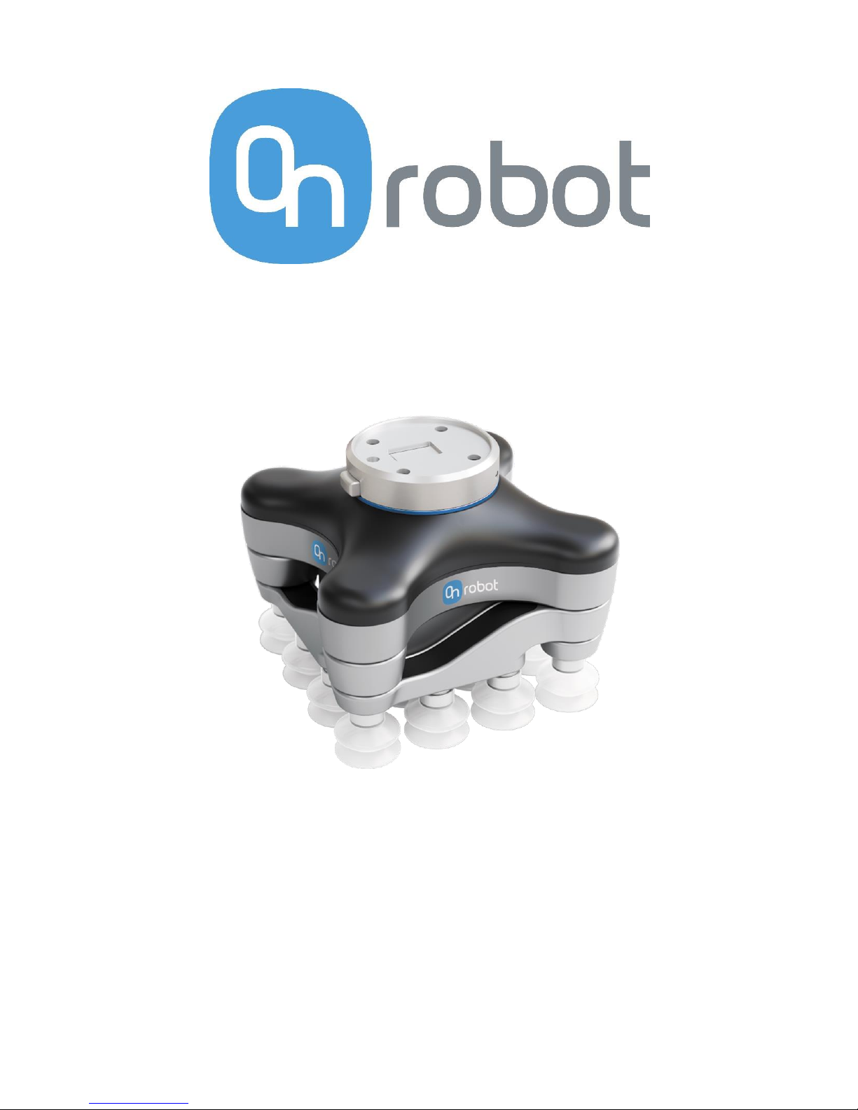
VG10 Vacuum Gripper
Collaborative dual-channel electrical vacuum gripper
Original Instructions (en)
Version 1.1.0
Page 2

Page 3

The information contained herein is property of OnRobot A/S and shall not be
reproduced in whole or in part without prior written approval of OnRobot A/S. The
information herein is subject to change without notice and should not be construed as
a commitment by OnRobot A/S. This manual is periodically reviewed and revised.
OnRobot A/S assumes no responsibility for any errors or omissions in this document.
Copyright © 2017–2018 by OnRobot A/S.
The OnRobot A/S logo is trademark of OnRobot A/S.
Page 4

VG10 Technical Sheet
Technical sheet
Features
• Easy installation, programming and risk assessment
• Optimized for collaborative applications
• Dual grip with two independent gripping zones
• No need for external air or cables down the robot
• 10 kg lifting power on airtight and slightly porous surfaces
• Plug’n’Produce in 30 minutes (installation + robot programming)
Minimum
Typical
Maximum
Unit
Vacuum
5 %
-0.05
1.5
-
-
-
80 %
-0.810
24
Vacuum
Bar
inHg
Air flow
0 - 12
Nl/min
Arms adjustment
0 - 270
°
Arm holding torque
- 6 -
Nm
Payload
0 0 - - 10
22
kg
lb
Recommended workpiece size
10x10
0.5x0.5
- - 500x500
20x20
mm
in
Vacuum cups
1 - 16
pcs.
Gripping time
-
0.35
-
s
Releasing time
-
0.20
-
s
Foot-inch-foot
-
1.40
-
s Feature
Vacuum pump
Integrated, electric BLDC
Arms
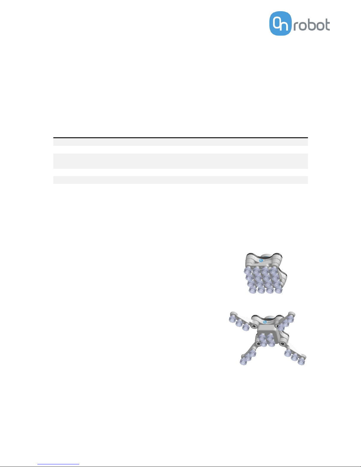
4, adjustable by hand
Tool changer
Integrated, click-on
Mechanical interface
ISO 9409-1, type 50-4-M6
Pneumatic interface
16x G1/8 internal threads
Electrical interface
8-pole M8
Digital interfaces
URCap (PolyScope ≥ 3.3)
UR scripts (PolyScope < 3.3)
MODBUS RTU
24V I/O
Dust filters
Integrated 50µm, field replaceable
IP Classification
IP54
Dimensions (folded)
146 x 146 x 102 mm
5.75 x 5.75 x 4.00 inch
Dimensions (unfolded)
390 x 390 x 102 mm
15.35 x 15.35 x 4.0 inch
Weight
1.70 kg
3.75 lb
Page 5
Typical applications
• Pick and place
• Palletizing
• Machine tending
• Material handling
Operating conditions
Minimum
Typical
Maximum
Unit
Power supply
20.4
24
28.8
Volts
Current consumption
50
600
1500
mA
Operating temperature
0
32 - -
50
122
°C
°F
Relative humidity (non-condensing)
0 - 95
%
Calculated MTBF (operating life)
30000 - -
hours
What’s in the box?
Everything you need to get started with the VG10 is included:
• 1 x VG10 Industrial Robot Vacuum Gripper
• 1 x Easy Tool Changer
• 1 x 200 mm M8 tool cable
• 16 x Fittings for vacuum cups (pre-mounted)
• 16 x 30 mm vacuum cups (pre-mounted)
• 4 x 40 mm vacuum cups
• 4 x 15 mm vacuum cups
• 16 x Blind screws
• 4 x Torx T30 M6 bolts
• 1 x pin (rotation lock)
• Torx 30 key
• 3 mm Allen hex key
• User manual
• USB stick
- URCaps (PolyScope >= 3.3 support)
- User manual
Page 6

VG10 User Manual 1.1.0
Page 6 of 40
Table of contents
Technical sheet .............................................................................................................4
Features .......................................................................................................................4
Typical applications .....................................................................................................5
Operating conditions ...................................................................................................5
What’s in the box? ........................................................................................................5
1 Quick guides ...............................................................................................................8
Installation ...................................................................................................................8
Troubleshooting ..........................................................................................................9
Updating software .......................................................................................................9
Uninstalling ............................................................................................................... 10
2 Software specification .......................................................................................... 10
URCap ....................................................................................................................... 10
The Installation Screen ......................................................................................... 11
Structures ............................................................................................................. 12
VG10 Grip ............................................................................................................. 12
VG10 Release ........................................................................................................ 14
Script commands ...................................................................................................... 15
VG10_grip (channel, vacuum, timeout, alert) ...................................................... 15
VG10_release(channel, timeout, autoidle) .......................................................... 15
VG10_get_vacuum(channel) ................................................................................ 16
VG10_calibrate_ain() ............................................................................................ 16
VG10_idle(channel) .............................................................................................. 16
MODBUS RTU ........................................................................................................... 17
Settings ................................................................................................................. 17
Function codes ...................................................................................................... 17
Registers ............................................................................................................... 18
Manual control ......................................................................................................... 20
3 Hardware specification ......................................................................................... 21
Vacuum cups and fittings ......................................................................................... 22
Page 7

Page 7 of 40
Payload, vacuum and air flow .................................................................................. 23
Suction area .......................................................................................................... 23
Vacuum ................................................................................................................. 24
Air flow ................................................................................................................. 24
Maintenance and repair ........................................................................................... 26
Filters .................................................................................................................... 26
Mechanical dimensions ............................................................................................ 27
Electrical characteristics ........................................................................................... 28
4 Safety ....................................................................................................................... 29
Intended use ............................................................................................................. 29
Risk assessment ........................................................................................................ 29
Environmental safety................................................................................................ 31
General safety instructions....................................................................................... 32
5 Warranties ............................................................................................................... 33
Patents ...................................................................................................................... 33
Product warranty ...................................................................................................... 33
Disclaimer ................................................................................................................. 33
6 Certifications .......................................................................................................... 34
Applied standards ..................................................................................................... 34
CE/EU Declaration of incorporation (Original) ..................................................... 37
Page 8
VG10 User Manual 1.1.0
Page 8 of 40
Figure 1.2
Figure 1.1
1 Quick guides
Installation
• Unpack the box (See What’s in the Box Section and the Unboxing
video: https://www.youtube.com/watch?v=SqK-ATtTP0E)
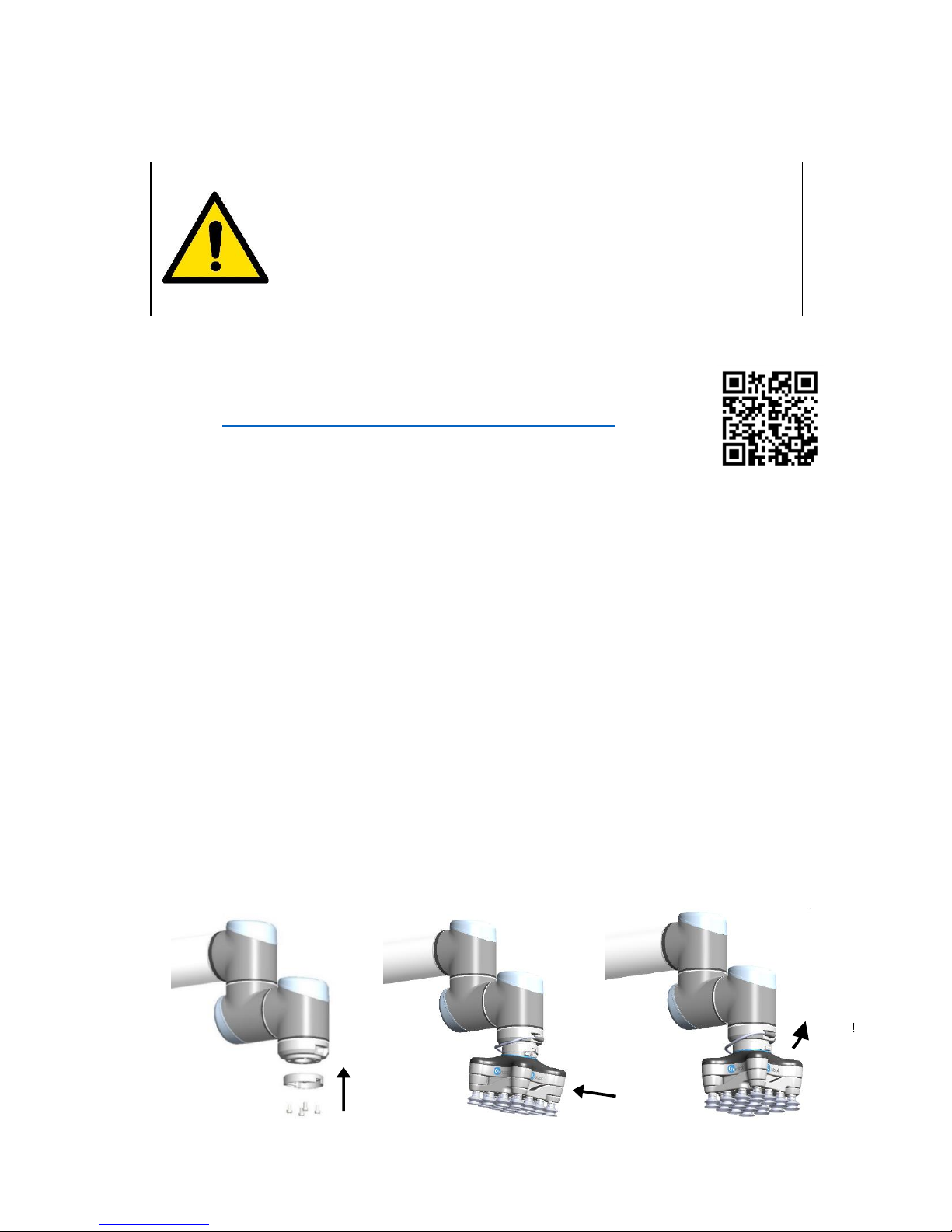
• Mount the tool changer on the robot:
- Orient the robot tool flange for easy access
- Unclick the robot half of the tool changer from the top of the VG10
- Screw it onto the robot using the four Torx T30 bolts, Torque = 6Nm (See Figure
1.1 below)
- Click on VG10 (See Figure 1.2 and 1.3 below)
• Mount the tool cable
- The cable fits smoothly 270º around the VG10 and tool changer (See Figure 1.3)
• Disable or uninstall other URCaps that use the tool connector
• Install the VG10 URCap
- Insert the supplied USB stick into the UR teach pendant
- UR Main Menu → Setup Robot → URCaps
- Press “+”
- Select USB stick → “VG10-URCap”
- Press “open”
- Press “restart”
• Ready
- Use the dedicated VG10 program structures to control the vacuum
- Move the four VG10 arms to your preferred angles; simply overcoming the
friction by hand
- Remove and add vacuum cups as you prefer; close unused holes with the blind
screws
DANGER
You must read, understand and follow all safety information in
this manual, and the robot manual and all associated
equipment before initiating robot motion. Failure to comply
with safety information could result in death or serious injury.
Click!
Figure 1.3
1x Ø6 mm Pin
4x M6 Torx30
Page 9

Page 9 of 40
Troubleshooting
• If the URCap is installed but the structures “VG10 Grip” or “VG10 Release” do not
work, try:
- Uninstall all URCaps, reboot UR control box and reinstall the VG10 URCap
- Check that the tool cable is undamaged and mounted correctly
- Check if a new empty program works
• If URCaps is not supported on the robot, try:
- Update the UR robot software to version 3.4 or higher
- Avoid URCap functionality by using the script commands, in the Script
Commands Section.
- Avoid URCap functionality by simply activating the tool I/O’s (Default vacuum
= 60%)
• If the program periodically stops with the condition “No controller” (i.e. UR
controller crash)
- Consult your local UR robot supplier for troubleshooting
Updating software
The software consists of the URCap and firmware inside the VG10. When an URCap is
installed on a robot it automatically includes the compatible firmware for the VG10.
Because the URCap and firmware comes as a pair, compatibility between the two is
guaranteed.
• Install the new URCap
- Simply follow the “installation” guide in this manual
• Update VG10 firmware
- UR main menu → Program Robot → Installation → VG10
- Wait a few seconds until the current firmware version appears
- If an “update” button appears: Press the button and wait until the new
firmware version is installed
- If no “update” button appears: The compatible firmware is already installed in
the VG10
INFO
• It is recommended to keep all robots in the same facility updated
with the same URCap version. By doing so, it is possible to switch
between different robots and VG10’s without the need to update
any software.
• The newest software is always available www.onrobot.com.
Page 10

VG10 User Manual 1.1.0
Page 10 of 40
Uninstalling
It is not necessary to uninstall the VG10 URCap to allow the IO’s to be used by other
URCaps / applications. The VG10 URcap can be activated or deactivated as needed per
installation by ticking the “Enable VG10 URCap” in the VG10 installation screen on and
off. Please refer to The Installation screen.
If needed, the URCap can be permanently uninstalled as described below.
• Uninstall the VG10 URCap
- UR Main Menu → Setup Robot → URCaps
- Select “VG10-URCap” on the list
- Press “-“
- Press “Restart”
• Remove the tool cable
• Remove the tool changer from the robot
- Orient the VG10 and robot tool flange for easy access
- Unclick the VG10
- Screw out the four Torx T30 bolts
2 Software specification
The most common way to use the VG10 is by use of the URCap functionalities (see
figure 2.1 for Installation tab and figure 2.2 for the Command tab). However, it is also
possible to use the VG10 without use of the URCap, either through urscript commands
or by manual I/O control. These three different control modes are described in the
following three sections.
URCap
The VG10 URCap allows for convenient and reliable usage of the VG10 with a Universal
Robots arm. When installed an installation tab and two program structures is made
available in PolyScope.
Page 11
Page 11 of 40
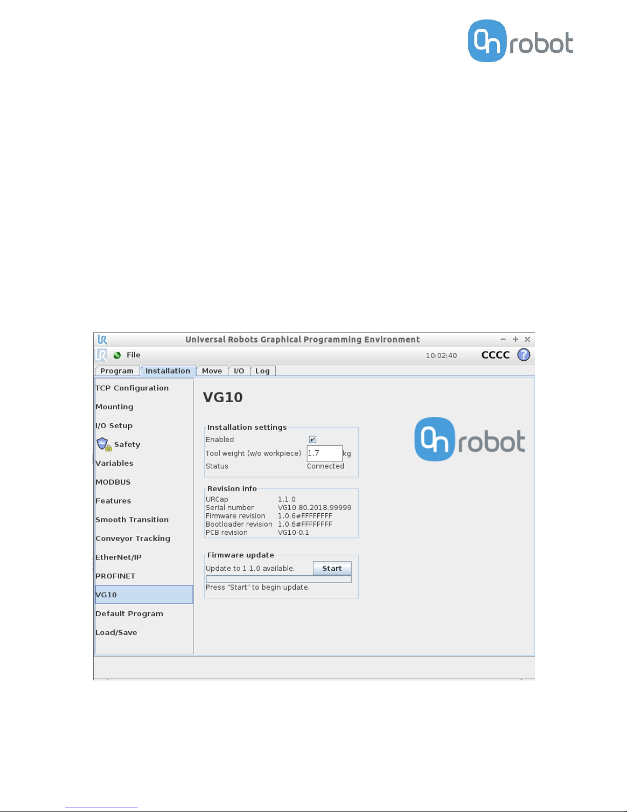
The Installation Screen
This tab contains general information and settings for the VG10. Serial and revision
numbers will automatically be transferred from the VG10 after a few seconds.
The VG10 URCap can be disabled per installation by unchecking the checkbox. This
option can be useful when multiple URCaps utilizing the tool IOs are installed on the
robot and used in different installations (See how to install in the Installation Section).
Tool weight should be set to the total weight including tool changes and other
accessories, but without the workpieces to be handled (see figure 2.2 )
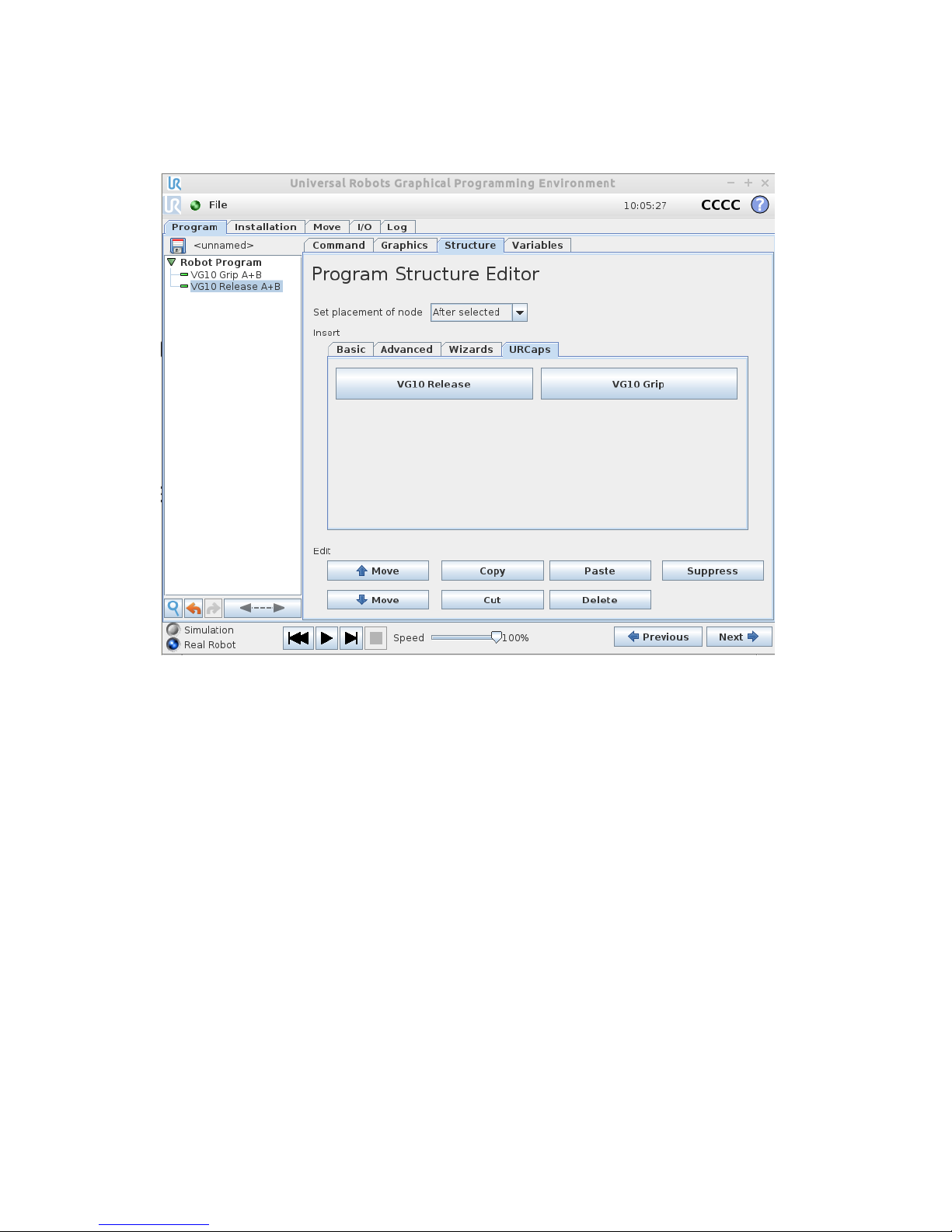
The structure tab is used to insert the Grip and Release function in the Robot program
structure tree (See figure 2.2). In the URCaps tab, you will find the two buttons.
If only the VG10 is mounted on the robot, the default setting of 1.7 kg should not be
changed.
An “Start” button will appear if a new firmware is available for the VG10. The update
time varies but is normally just a few minutes.
Figure 2.1: VG10 URCap Installation tab screen.
Page 12
VG10 User Manual 1.1.0
Page 12 of 40
Structures
The structure tab is used to insert the Grip and Release function in the Robot program
structure tree (See figure 2.2 below). At the URCaps tab you will find the two buttons.
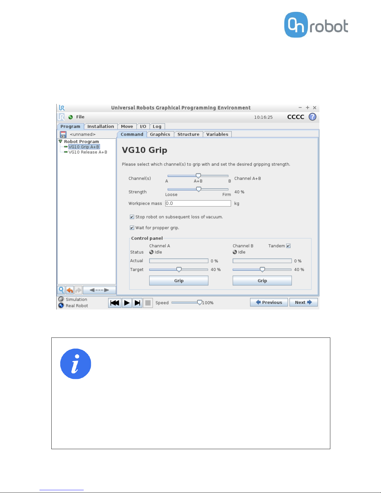
VG10 Grip
This structure is used to activate the pump and generate vacuum (see figure 2.3). It is
possible to select channel A, B or both (See stickers under the VG10 arms to see which
arms channel A is and which is channel B). The higher vacuum percentage the more
lifting power.
The VG10 URCap keeps track of total payload, when using the VG10 Grip and VG10
Release nodes along with the tool weight in the installation node to manage payload
settings. If, for instance, the tool weight is set to 1.7 kg in the VG10 Installation tab
and a payload of 2 kg is picked up on Channel A, using the VG10 Grip node, the total
payload is automatically set to 1.7 + 2 = 3.7 kg. If picking up an additional payload of 4
kg on Channel B, the total payload is automatically set to 1.7 + 2 + 4 = 7.7 kg. Likewise,
payload is removed per channel. If, in the above example, the workpiece on channel A
is removed using the VG10 Release structure, the total payload is automatically
adjusted to 1.7 + 4 = 5.7 kg.
The setting “wait for proper grip” means that the program will stay in the VG10 Grip
structure until commanded vacuum is achieved. The setting “Stop robot on
subsequent lost grip” means that the vacuum is monitored continuously and if the
vacuum disappears unexpectedly the robot will stop with a popup.
Figure 2.2: URCap Structure tab for VG10 Grip.
Page 13
Page 13 of 40
The indicator Actual and Target slide bar shows and defines, respectively, the current
and target vacuum in each channel. The ‘Grip’ button will start the pump and generate
vacuum at the selected level on the selected channel(s) to allows for easy verification
of the dialed in settings. The Release button makes it convenient to terminate the
test-grip and releasing any workpieces that may be held by the selected channel. The
Tandem button allows to control both channels at the same time when checked.
INFO
• Setting a lower vacuum gives a faster grip with less wear on the
vacuum cups. It also reduces the risk of leaving suction marks on
delicate work pieces.
• It can take a few seconds when pressing “Play” or “Test” before
the robot program starts. This is normal.
• When the two channels are set to different vacuum percentages
the VG10 automatically releases air into the channel with lower
pressure. This feature is activated when the pressure is more
than 20% vacuum over the setting. Releasing air generates a
characteristic rumbling sound and change in pumping speed.
Figure 2.3: URCap Command tab for VG10 Grip.
Page 14
VG10 User Manual 1.1.0
Page 14 of 40
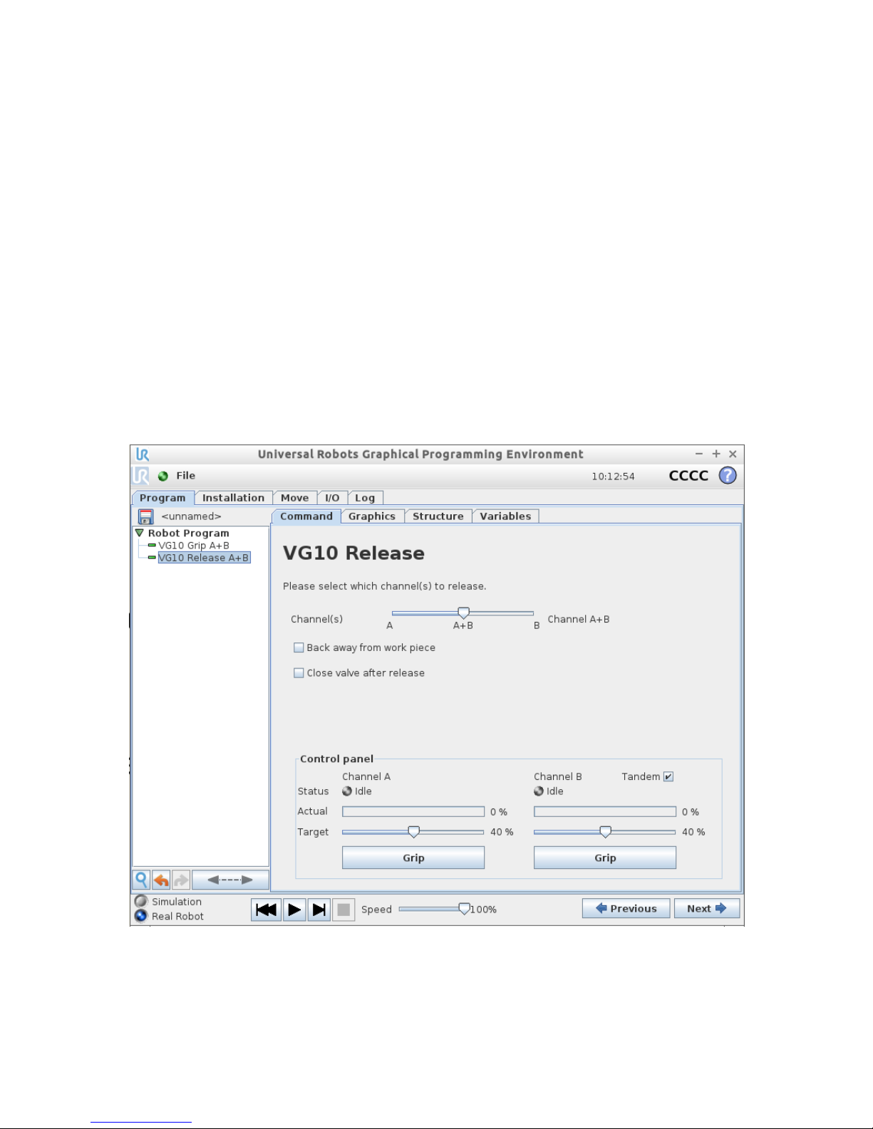
VG10 Release
This structure is used to release the grip of the workpiece by removing vacuum. By
selection the appropriate channel setting it is possible to release the workpiece on
either channel or both.
When the payload is properly set in the preceding VG10 Grip node(s), the robot
payload is corrected once the workpiece has been released. If, for instance, a
workpiece of 1 kg is held by Channel A and one of 2 kg by Channel B, the robot payload
is changed depending on the channel selection. Releasing channel A will set the
payload to 2 kg + tool weight whilst releasing channel B will set the payload to 1 kg +
tool weight. Releasing channel A+B will set the robot payload to the tool weight alone.
Please refer to The Installation screen for details on the tool weight.
The option to close the valves after the workpiece is released will turn off the power
to the release-valves to save power. The power will be removed when the robot has
traveled 5cm away from the release position. This option is especially suitable for
situation where multiple work pieces are handled, as turning off the valve will free up
power to the pump to improve vacuum levels and cycle times.
Figure 2.4: URCap Command tab for VG10 release.
Page 15

Page 15 of 40
Script commands
Script commands are available independently of the URCap and they also work on
older versions of the UR robots (Regarding old UR robots, follow the guide in the
folder “Script Commands” on the USB stick).
Script commands are available for both UR robots with the URCap installed and for
older robots without URCAP support. For the VG10 script commands to become
available on an UR robot, one of the following must be done:
• Install the VG10 URCap, or
• Follow the guide in the folder “Script Commands” on the USB stick, or
• Follow the guide found on www.onrobot.com/support.
VG10_grip (channel, vacuum, timeout, alert)
Commands the VG10 to perform a grip.
• channel: Tells which channel to be gripped with.
- 0 = Channel A
- 1 = Channel B
- 2 = Channel A and Channel B
If not set, this parameter defaults to 2 (A and B).
• vacuum: Tells how hard to grasp in the range of 0% to 80 % vacuum.
- 60 = 60% vacuum. A typical firm grip
- 30 = 30% vacuum. A typical soft grip
If not set, this parameter defaults to 60%.
• timeout: Tells how long to wait for commanded vacuum to be achieved. If vacuum
is not achieved, an air leakage at the workpiece or vacuum cups is reported in a
popup and the robot program stops.
- 0 = The function will not wait for vacuum, but return immediately after the
command is sent
- >0 = Waiting time [s]. Floating point numbers can be used. E.g. 0.6 = 600 ms.
If not set, this parameter defaults to 5 seconds.
• alert: Whether the grip should be monitored after vacuum (grip) is established. If
vacuum is lost while handling a workpiece, a popup warning is shown, and the
robot program stops. This setting cannot be used without a proper timeout
setting, see above.
- False = Vacuum is not monitored
- True = Vacuum is continuously monitored. Popup warning enabled
If not set, this parameter defaults to True.
VG10_release(channel, timeout, autoidle)
Commands the VG10 to perform a release.
• channel: Tells which channel to be released.
- 0 = Channel A
- 1 = Channel B
- 2 = Channel A and Channel B
If not set, this parameter defaults to 2 (A and B).
Page 16

VG10 User Manual 1.1.0
Page 16 of 40
• timeout: Tells how long to wait for vacuum to be removed.
- 0 = The function will not wait, but return immediately after the command is
sent
- >0 = Waiting time [s]. Floating point numbers can be used. E.g. 0.6 = 600ms.
If not set, this parameter defaults to 5 seconds.
• autoidle: Tells if the release valve should automatically be turned off when the
release is completed and the robot has moved 5cm away from the release position.
If not set, this parameter defaults to True.
VG10_get_vacuum(channel)
Returns current vacuum in the selected channel.
• channel: Tells which channel value to return.
- 0 = Channel A
- 1 = Channel B
VG10_calibrate_ain()
Runs a calibration process improving accuracy of the script commands
VG10_get_vacuum() and VG10_grip(), by compensating out tolerances of the UR
robot analog inputs. Typically, this takes 200 ms and is done once in the beginning of
a program if using the VG10 URcap.
VG10_idle(channel)
Commands the VG10 to idle the selected channel. When a channel is in idle, the power
consumption is slightly lower, but parts may 'stick' to the suction cup as the air return
channel is closed.
• channel: Tells which channel to be in idle.
- 0 = Channel A
- 1 = Channel B
- 2 = Channel A and Channel B
Page 17

Page 17 of 40
MODBUS RTU
The VG10 supports MODBUS RTU. MODBUS RTU is a well proven and easy to use
fieldbus, which is supported by a vast amount of industrial equipment. MODBUS RTU
uses RS485 as the physical layer. For further details on the protocol, please refer to
modbus.org’s MODBUS over Serial Line Specification and Implementation Guide1 and
MODBUS Application Protocol Specification2
Settings
Both 24V I/O data line and MODBUS RTU line is enabled at power-up. If the VG10
detects a command on the 24V I/O data line before receiving a MODBUS RTU frame,
it will disable MODBUS RTU and use the shared MODBUS RTU line (RS485) for analog
outputs (Vacuum %).
Upon reception of the first valid MODBUS frame, the VG10 will lock to this interface
and disables the 24V I/O data line.
The table below states the settings to be used when communicating with the VG10
over MODBUS RTU. See Electrical Characteristics for physical connection details.
Setting
Value
Baudrate [bit/sec]
115200
Start bits
1
Data bits
8
Parity
Even
Stop bits
1
Slave address
65 (0x41)
CRC Check
16 bit (MODBUS default)
CRC Polynomial
0xA001 (MODBUS default)
Function codes
The VG10 currently supports the function codes listed below. The VG10 will respond
with an appropriate exception code, if the function is not executed correctly. Please
refer to MODBUS Application Protocol for detailed description of the different
exception codes. Note that the VG10 will provide no response, if the serial settings,
slave address or CRC code is not correct.
3 / 0x03, Read Holding Registers:
Use this function code to read out one or multiple consecutive registers. Please refer
to MODBUS Application Protocol for frame and response details.
6 / 0x06, Write Single Register:
Use this function code to set the value of a single register. Please refer to MODBUS
Application Protocol for frame and response details.
1
http://www.modbus.org/docs/Modbus_over_serial_line_V1_02.pdf
2
http://www.modbus.org/docs/Modbus_Application_Protocol_V1_1b.pdf
Page 18

VG10 User Manual 1.1.0
Page 18 of 40
16 / 0x10, Write Multiple Registers:
Use this function code to set the values of multiple consecutive registers. Please
refer to MODBUS Application Protocol for frame and response details.
23 / 0x17, Read/Write Multiple Registers:
Use this function code to set the values of- and read out one or multiple consecutive
registers. Note that the registers to be set are set before the registers to be read are
read. Please refer to MODBUS Application Protocol for frame and response details.
Registers
The table below provides an overview of the available MODBUS registers in the VG10.
All writable registers can be accessed using function codes 6, 16 or 23. All readable
registers can be accessed using function codes 3 or 23.
Address
Register
Access
0
0x0000
Channel A Control
Read + Write
1
0x0001
Channel B Control
Read + Write
2
0x0002
Current limit
Read + Write
18
0x0012
Channel A actual vacuum
Read only
19
0x0013
Channel B actual vacuum
Read only
20
0x0014
Supply current
Read only
21
0x0015
Supply voltage
Read only
22
0x0016
Internal 5V voltage
Read only
23
0x0017
Temperature
Read only
24
0x0018
Pump speed
Read only
0 / 0x0000, Channel A Control (Read + write)
This register allows for control of channel A. The register is split in two 8-bit fields:
Bits 15-8
Bits 7-0
Control mode
Target vacuum
The control mode field must assume one of these three values:
0 / 0x00, Release. Commands the channel to release any work item and stop the
pump, if not required by the other channel.
1 / 0x01, Grip. Commands the channel to build up and maintain vacuum on this
channel.
2 / 0x02, Idle. Commands the channel to neither release nor grip. Workpieces may
‘stick’ to the channel if physically pressed towards its vacuum cups, but the VG10 will
use slightly less power.
The target vacuum field sets the level of vacuum to be build up and maintained by the
channel. It is used only when the control mode is 1 (0x01) / Grip. The target vacuum
should be provided in % vacuum. It should never exceed 80.
Examples:
Setting the register value 0 (0x0000) will command the VG10 to release the work
Page 19

Page 19 of 40
item.
Setting the register value 276 (0x0128) will command the VG10 to grip at 20 %
vacuum.
Setting the register value 296 (0x0128) will command the VG10 to grip at 40 %
vacuum.
Setting the register value 331 (0x014B) will command the VG10 to grip at 75 %
vacuum.
Setting the register value 512 (0x0200) will command the VG10 to idle the channel.
1 / 0x0001, Channel B Control (Read + write)
This register allows for control of channel B. See 0: Channel A Control above.
2 / 0x0002, Current limit (Read + write)
Set and read the current limit. The limit is provided and must be given in mA (milliamperes). The limit is 500mA per default and should never be set above 1000 mA.
18 / 0x0012, Channel A actual vacuum (Read only)
Reads the actual vacuum on Channel A. The vacuum is provided in permille (1/1000)
absolute vacuum. Please note that this differs from the setpoint given in percent, as
extra accuracy is desirable on the actual vacuum.
19 / 0x0013, Channel B actual vacuum (Read only)
Same as 18, but for Channel B.
20 / 0x0014, Supply current (Read only)
Reads the actual supply current in mA (milliamperes). Use this reading for diagnostics
only. Should never be used for process control.
21 / 0x0015, Supply voltage (Read only)
Reads the actual supply voltage in mV (millivolts). Use this reading for diagnostics
only. Should never be used for process control.
22 / 0x0016, Internal 5V supply voltage (Read only)
Reads the actual voltage of the internal 5V supply in mV (millivolts). Use this reading
for diagnostics only. Should never be used for process control.
23 / 0x0017, Temperature (Read only)
Reads the actual internal temperature in 1/100 degrees Celsius. Use this reading for
diagnostics only. Should never be used for process control.
24 / 0x0018, Pump speed (Read only)
Reads the current pump motor speed in RPM (rotations per minute). Use this reading
for diagnostics only. Should never be used for process control.
Page 20
VG10 User Manual 1.1.0
Page 20 of 40
Manual control
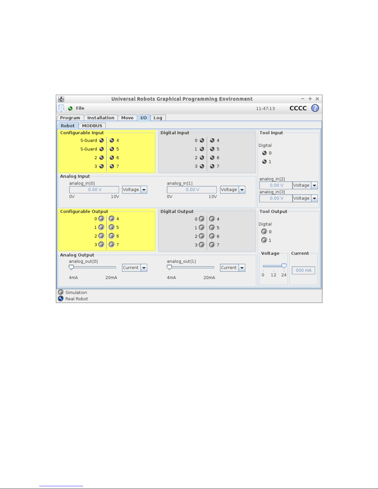
It is possible to use the VG10 completely without URCAP and script commands. This is
done by controlling the UR tool I/O directly, see UR tool I/O tab on the right side of
the screenshot below.
The UR I/O tab provides some basic manual features:
• TAI0 = Analog_in[2] = Vacuum in channel A (1V per 10% vacuum)
• TAI1 = Analog_in[3] = Vacuum in channel B (1V per 10% vacuum)
• TO0 = Tool_digital_out[0] = On/Off control channel A (vacuum preset to 60%)
• TO1 = Tool_digital_out[1] = On/Off control channel B (vacuum preset to 60%)
• TI0 = Tool_digital_input[0] = Vacuum present channel A (Vacuum > 40%)
• TI1 = Tool_digital_input[1] = Vacuum present channel B (Vacuum > 40%)
To use the basic manual features, the following must be observed:
• Tool digital I/O only works without the URCap installed
• The tool analog input range must be set to voltage [0-10V]
• The tool voltage must be set to 24V
• Reset the VG10 by turning the tool voltage off (0V) and then on again (24V)
Page 21
Page 21 of 40
3 Hardware specification
General product details and environmental conditions are found in the Technical Sheet
on page 4.
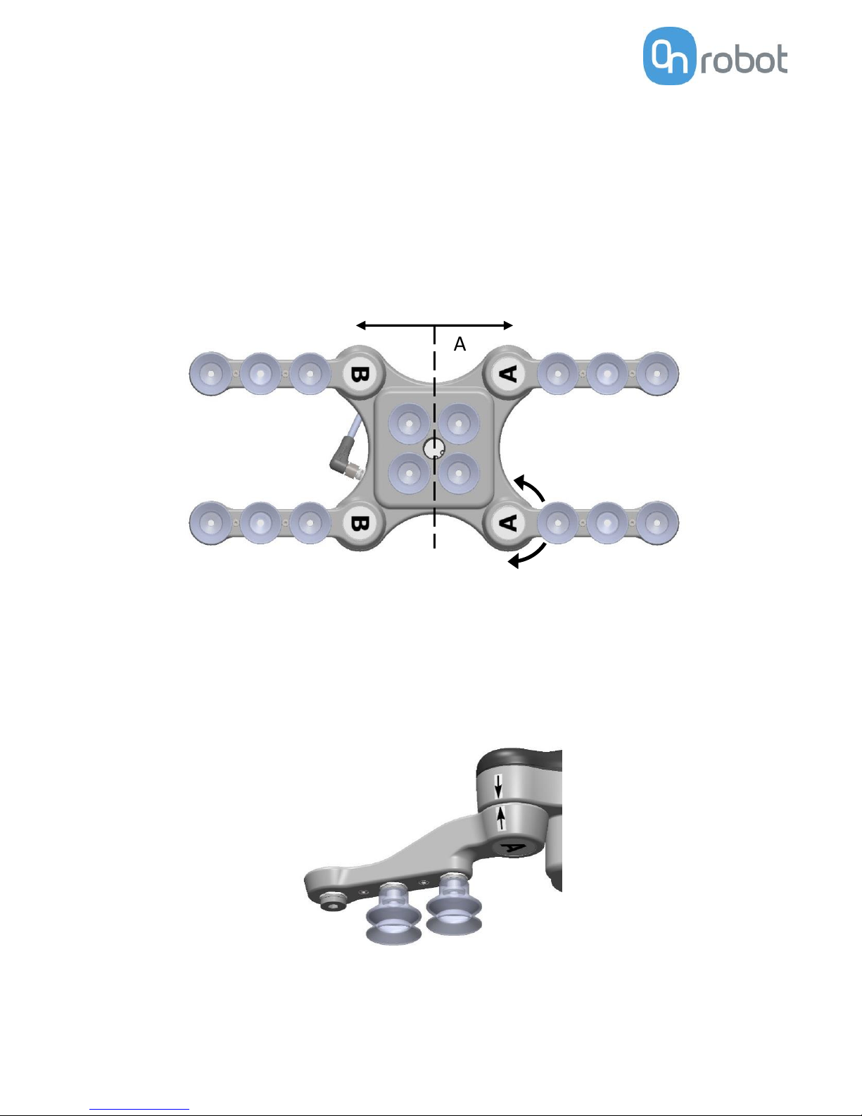
The arms of the VG10 can be folded to the preferred position simply by pulling in the
arms. The torque needed to overcome the friction in the rotatable joints of the arm is
high (6 N/m) to ensure that the arms do not move when handling 10 kg payloads.
The VG10 suction cups are grouped into two independent channels (see figure 3.1).
When the four arms are adjusted to preferred angles, it is recommended to add the
accompanied arrow stickers. This allows for easy realignment and exchanging
between different work items.
B A
6Nm
Figure 3.1: Independent vacuum zones A and B shown.
Figure 3.2: Arrow sticker shown for easy alignment.
Page 22
VG10 User Manual 1.1.0
Page 22 of 40
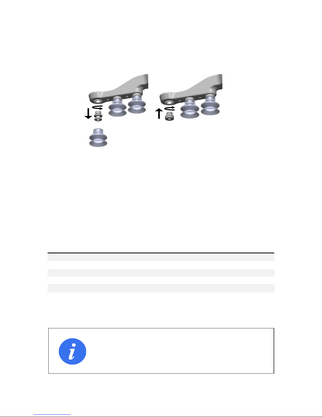
Vacuum cups and fittings
It is possible to change suction cups simply by pulling them off the fittings. Unused
holes can be blinded using a blind screw, and each fitting can be changed to a different
type to match the desired suction cup. Use a 3 mm Allen key for changing to blind
screws or another type of fitting (See figure 3.3 below).
The thread size is the commonly used G1/8”; allowing for standard fittings, blinders
and extenders to be fitted directly to the VG10 arms and housing, see mechanical
details in the Mechanical Dimensions Section.
Choosing the right vacuum cups for your application is essential. The VG10 comes with
common 30 mm silicone vacuum cups which are good for hard and flat surfaces, but
not good for uneven surfaces and it might leave microscopic traces of silicone on the
workpiece which can cause issues with some types of painting processes afterwards.
Below is a list with general recommendations.
Table: Choosing a vacuum cup type
Workpiece surface
Vacuum cup shape
Vacuum cup material
Hard and flat
Normal or dual lip
Silicone or NBR
Soft plastic or plastic bag
Special plastic bag type
Special plastic bag type
Hard but curved or uneven
Thin dual lip
Silicone or soft NBR
To be painted afterwards
Any type
NBR only
Varying heights
1.5 or more bevels
Any type
INFO
It is recommended to consult a vacuum cup specialist to find the
optimal vacuum cup where the standard types are insufficient.
Figure 3.3: G1/8 thread behind the existing fitting.
Changing to another fitting or blind is possible.
Page 23
Page 23 of 40
Payload, vacuum and air flow
The lifting capacity (payload) of the VG10 depends primarily on the following
parameters:
• Suction area
• Vacuum
• Air flow
These three parameters are explained in the following subsections.
Suction area
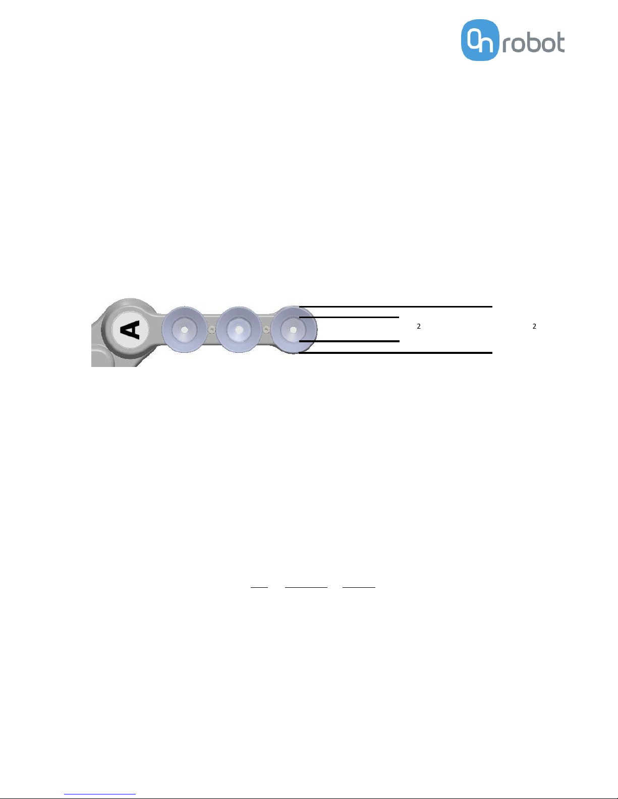
The higher suction area, the higher lifting capacity. Be aware that the actual suction
area is smaller than the outer diameter of your vacuum cups, as the vacuum cup libs
forms around the workpiece, the actual suction area is reduced (see figure 3.4).
With a typical vacuum of 60% and one vacuum cup with a 200 mm2 suction area, the
lifting force is:
With this force per vacuum cup, to lift 10 kg and accelerate with 2g’s, this many
vacuum cups are needed:
16 vacuum cups
It is often a good idea to use more vacuum cups than needed, to accommodate for
vibrations, leaks and other unexpected conditions. However, the more vacuum cups,
the more air leakage (air flow) is expected and the more air is moved in a grip resulting
in longer gripping times.
2
Ø30 mm = 700 mm2
Figure 3.4: Available suction cup area for the standard Ø30 mm suction cup.
Page 24
VG10 User Manual 1.1.0
Page 24 of 40
Vacuum
Vacuum is defined as the percentage of absolute vacuum achieved relative to
atmospheric pressure, i.e.:
The vacuum percentage setting is the target vacuum. The pump will run at full speed
until the target vacuum is achieved, and then run at a lower speed necessary to
maintain the target vacuum.
The pressure in the atmosphere varies with weather, temperature and altitude. The
VG10 automatically compensates for altitudes up to 2km, where the pressure is about
80% of sea level.
Air flow
Air flow is the amount of air that must be pumped to maintain the target vacuum. A
completely tight system will not have any air flow, whereas real life applications have
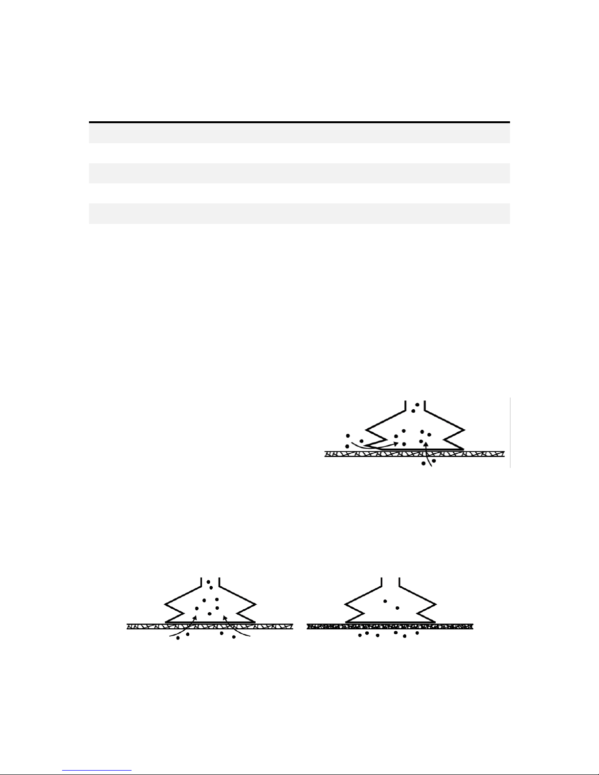
some smaller air leakages from two different sources:
• Leaking vacuum cup lips
• Leaking workpieces
The smallest leak under a vacuum cup can be
hard to find (see figure 3.5). Choosing the
right vacuum cups are essential, (Table:
Choosing a vacuum cup type).
Leaking workpieces can be even harder to identify. Things that look completely tight
might not be tight at all. A typical example is coarse cardboard boxes. The thin outer
layer is often requiring a lot of air flow to create a pressure difference over it (see
figure 3.6 below).
% vacuum
Bar
kPa
inHg
Typically used for
0%
0.00 rel.
1.01 abs.
0.00 rel.
101.3 abs.
0.0 rel.
29.9 abs.
No vacuum / No lifting capacity
20%
0.20 rel.
0.81 abs.
20.3 rel.
81.1 abs.
6.0 rel.
23.9 abs.
Cardboard and thin plastics
40%
0.41 rel.
0.61 abs.
40.5 rel.
60.8 abs.
12.0 rel.
18.0 abs.
Light workpieces and long suction cup life span
60%
0.61 rel.
0.41 abs.
60.8 rel.
40.5 abs.
18.0 rel.
12.0 abs.
Heavy workpieces and strongly secured grips
80%
0.81 rel.
0.20 abs.
81.1 rel.
20.3 abs
23.9 rel.
6.0 abs.
Max. vacuum. Not recommended
Figure 3.5: Visualization of leakage
possibilities.
Figure 3.6: Visualization of difference in leakage through workpieces.
Page 25
Page 25 of 40
Therefore, the users must be aware of the following:
• VG10 is not suitable for most uncoated, coarse cardboard boxes.
• Extra attention must be paid to leakages, e.g. vacuum cup shape and surface
roughness
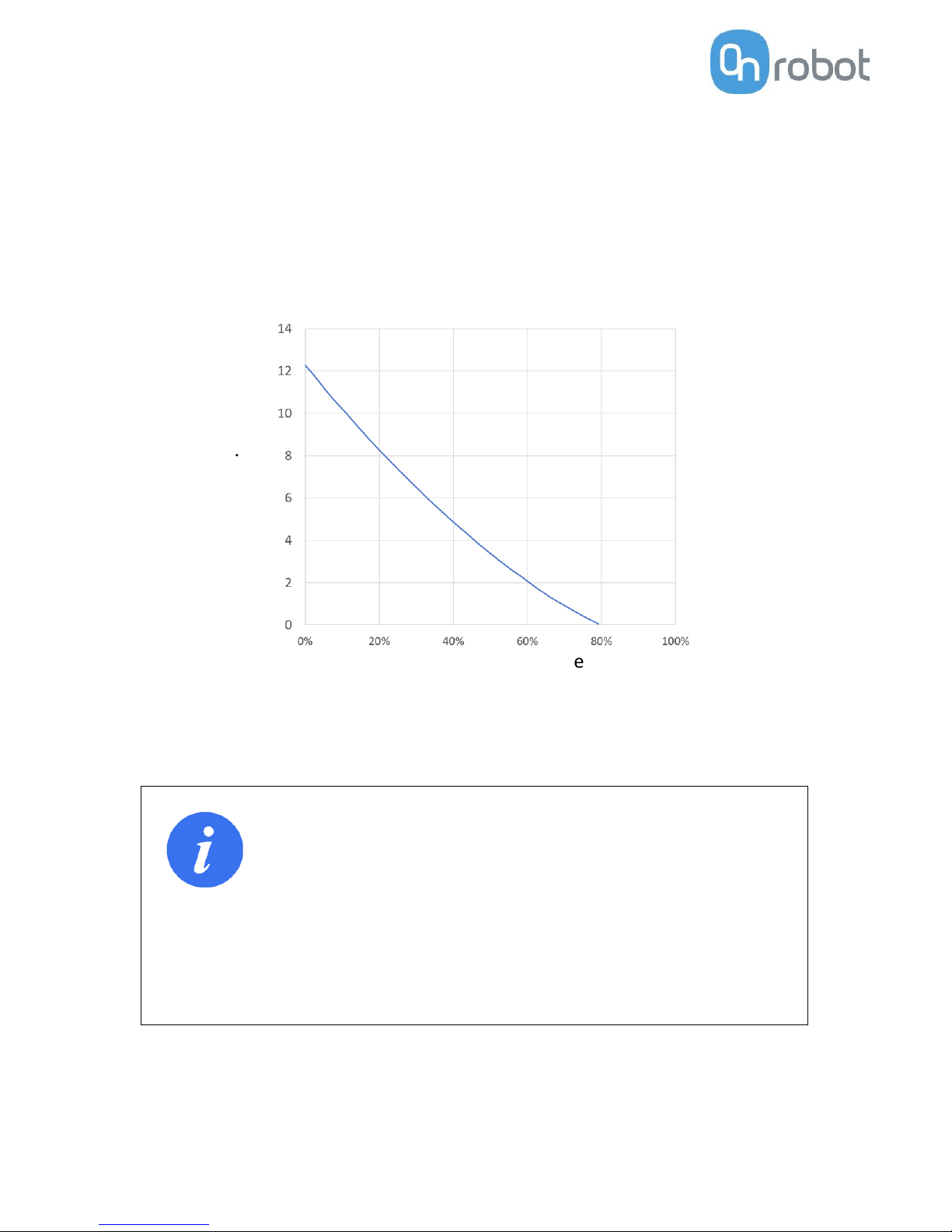
The air flow capability of a VG10 is shown in the graph below:
INFO
• The easiest way to check if a cardboard box is sufficiently tight
is simply to test it using the VG10.
• A high vacuum percentage setting does not give a higher lifting
capacity on corrugated cardboard. In fact, a lower setting is
recommended, e.g. 20%.
• A low vacuum setting results in less air flow and less friction
below the vacuum cups. This means VG10 filters and vacuum
cups will last longer.
VG10 pump, air flow
Nl/min.
Vacuum procentage
Page 26
VG10 User Manual 1.1.0
Page 26 of 40
Maintenance and repair
All maintenance and repairs must be performed in compliance with this manual,
including safety instructions.
Only use original spare parts.
Filters
The VG10 is equipped with one filter for each suction cup socket, and one filter for the
exhaust. How often the filters need to be changed depends on the nature of the work
piece and the working environment. The VG10 automatically de-dust the filters every
time a grip is released. However, particles can eventually get stuck and build up inside
the filter, lowering the VG10 performance.
A filter service kit is available, which include both new filters and tools needed.
• Filter service kit, PN 17001
Neither use nor power on the VG10 without filters. Dust, hair and larger particles can
get stuck in pump membranes and valve seats, causing permanent damage to the
VG10.
DANGER
• Identify how often the filters needs service and schedule
maintenance with a fixed period short enough to ensure a firm
grip at all times.
• An overall inspection of the VG10 must be performed regularly
and at least once every 6 months.
• Never power the VG10 without filters or with filters mounted
incorrectly. Failure to comply with this precaution can cause
irreversible failure of pump or valves.
Page 27
Page 27 of 40
Mechanical dimensions
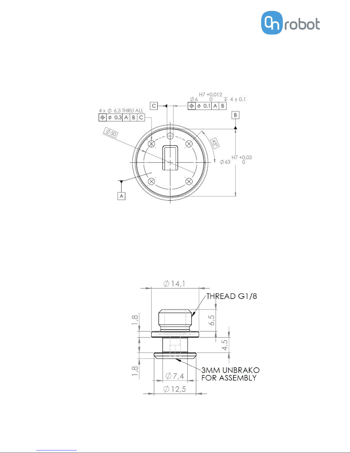
The mechanical mounting interface on the VG10 is a standard robot flange according
to ISO 9409-1, Type 50-4-M6. Dimensions and tolerances are noted in mm in the
drawing below.
Dimensions of the fitting supplied with the VG10 is shown below. Other suction cups
/ fittings with G1/8 x 6.5 mm threading is directly compatible with the VG10.
Page 28
VG10 User Manual 1.1.0
Page 28 of 40
Electrical characteristics
The VG10 supports a wide range of control methods, making it suitable for all of the
following:
• Universal Robots – URCap, scripts and manual I/O control
• Other robots – Manual 24 V I/O control and MODBUS RTU (RS485) commands
• PLC – Manual 24 V I/O control and MODBUS RTU (RS485) commands
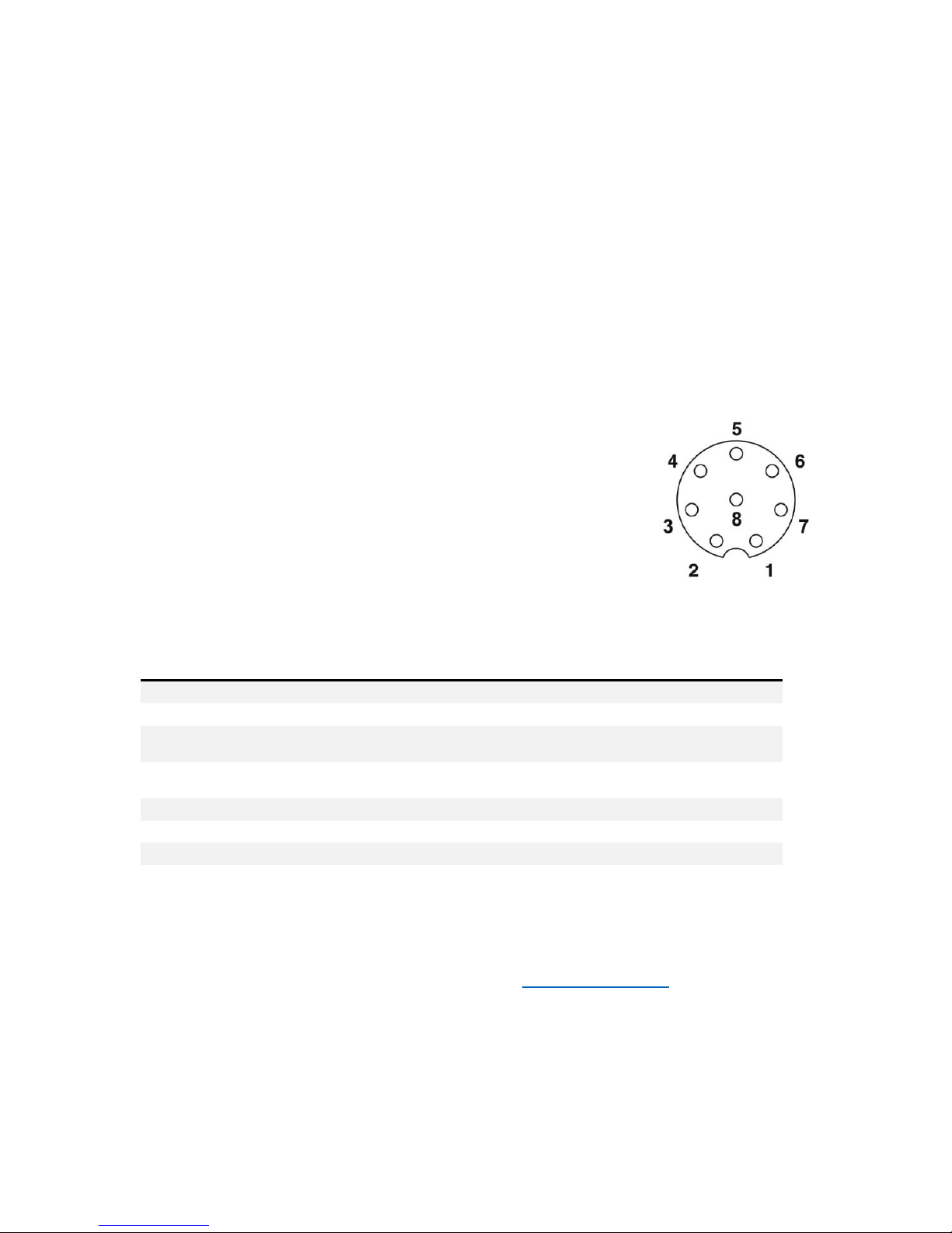
The connector on the VG10 is an 8-way, coding A, gold contacts as defined in IEC
61076-2-104. The following cables are compliant and recommended:
• OnRobot A/S, 200 mm male-female, PN 10071
• Phoenix contact, 200 mm male-female, PN 1416505
• Phoenix contact, 10 meter open ended PN 1404183
The 24V I/O signals in the VG10 control cable are constructed for
reliable communication with robots and PLC’s conforming to IEC
61131-2. Below is an overview of the signals and their respective
functions:
By default, the VG10 support basic manual control through simple 24V PLC I/Os, see
manual control on page 17. OnRobot A/S continuously improve guidance and features
for different robot manufacturers; find more on www.onrobot.com.
Pin
Color
Primary function
Alternate function
Manual function
UR I/O
5
Grey
+24V <600mA
+24V <1500mA
Power
8
Red
GND / 0V / Shield
0V/GND
7
Blue
Data input (npn)
Data input (pnp)
CHA On/Off
DO8/TO
0
6
Pink
Data input (npn)
Data input (pnp)
CHB On/Off
DO9/TO
1
4
Yellow
Data output (pnp)
CHA vacuum OK
DI8/TI0
3
Green
Data output (pnp)
CHB vacuum OK
DI9/TI1
1
White
Analog output
MODBUS RS485 (–)
CHA vacuum %
AI2
2
Brown
Analog output
MODBUS RS485 (+)
CHB vacuum %
AI3
Page 29

Page 29 of 40
4 Safety
The robot integrators are responsible for ensuring that the applicable safety laws and
regulations in the country concerned are observed and that any significant hazards in
the complete robot application are eliminated. This includes, but is not limited to:
• Performing a risk assessment for the complete robot system
• Interfacing other machines and additional safety devices if defined by the risk
assessment
• Setting up the appropriate safety settings in the robot software
• Ensuring that the user will not modify any safety measures
• Validating that the total robot system is designed and installed correctly
• Specifying instructions for use
• Marking the robot installation with relevant signs and contact information of the
integrator
• Collecting all documentation in a technical file; including the risk assessment and
this manual
Intended use
The VG10 is intended to be used as end-of-arm tooling on industrial robots with
payloads up to 10 kg, in industrial pick-and-place, palletizing and machine tending
applications. The VG10 should only operate under conditions noted in the Technical
Sheet.
Any use or application deviating from intended use is deemed to be impermissible
misuse. This includes, but is not limited to:
• Use in potentially explosive atmospheres
• Use in medical and life critical applications
• Use before performing a risk assessment
• Use outside the permissible operational conditions and specifications
• Use close to a human’s head, face and eye area
• Use as a climbing aid
The VG10 is equipped with features that are only available when integrated with a
Universal Robot. Please contact your supplier for additional installation guidance if
used with other types of robots.
Risk assessment
The robot integrator must perform a risk assessment on the complete robot
application. The VG10 is only a component in a robot application and the safe use of
the VG10 rely on the integrators ability to design a safe robot application.
The VG10 is designed with features especially suitable for collaborative applications:
Page 30

VG10 User Manual 1.1.0
Page 30 of 40
• Smooth and round design without any sharp edges or pinch points. Radius 2 mm
or higher.
• Friction clutch in all four arms makes them able to turn under a hard collision.
Torque approx. 6 N/m. (Patent pending)
• Valves stays in the grip position under emergency stop, which can prevent a work
item from flying out of the VG10. Vacuum is typically lost after a few seconds.
• The build-in tool changer is oversized and based on a redundant locking
mechanism. (Patent pending)
In collaborative applications the trajectory of robot can play a significant safety role.
The integrator must consider the angle of contact with a human body, e.g. orientate
the VG10 and work item so that the contact surface in the direction of movement is as
large as possible, and so that tool connectors are pointed in the direction opposite to
the movement. It is recommended to orientate the VG10 arms perpendicular to the
direction of movement to make them able to move under a hard collision.
OnRobot A/S have identified the potential hazards listed below as significant hazards
that must be considered by the integrator:
• Objects flying from the VG10 due to loss of grip
• Objects falling down from the VG10 due to loss of grip
• Injuries due to collisions between humans and work items, VG10, robot or other
obstacles
• Consequences due to loosen bolts
• Consequences if the VG10 cable gets stuck to something
• Operation with the robot half of the tool changer mounted, but without the VG10
clicked on
It is recommended that the VG10 is integrated in compliance with in the following
guides and standards:
• ISO 10218-2
• ISO 12100
• ISO/TR 20218-1
• ISO/TS 15066
Page 31

Page 31 of 40
Environmental safety
OnRobot A/S products must be disposed of in accordance with the applicable national
laws, regulations and standards.
The product is produced with restricted use of hazardous substances to protect the
environment; as defined by the EU RoHS directive 2011/65/EU. These substances
include mercury, cadmium, lead, chromium VI, polybrominated biphenyls and
polybrominated diphenyl ethers.
Observe national registration requirements for importers according to EU WEEE
Directive 2012/19/EU.
Page 32
VG10 User Manual 1.1.0
Page 32 of 40
General safety instructions
Generally, all national regulations, legislations and laws in the country of installation
must be observed. Integration and use of the product must be done in compliance with
precautions in this manual. Particular attention must be paid to the following
warnings:
DANGER
• You must read, understand and follow all safety information in
this manual, and the robot manual and all associated
equipment before initiating robot motion. Failure to comply
with safety information could result in death or serious injury.
• Robot applications must be constructed in such way that a loss
of grip, for whatever reason, does not result in any injury to
humans or animals.
• Identify how often the filters needs service and schedule
maintenance with a fixed period short enough to ensure a firm
grip at all times. An overall inspection of the VG10 must be
performed regularly and at least once every 6 months.
• Bolts that are insufficiently secured or repetitive overloads can
cause the product to separate unexpectedly.
• The VG10 must not be used for collaborative applications
where the work item itself represents a hazard. Necessary
measures must be taken to avoid changes in work items which
has not been addressed by the risk assessment.
• The information in this manual does not cover designing,
installing and operating a complete robot application, nor does
it cover other peripheral equipment that can influence the
safety of the complete system. The complete system must be
designed and installed in accordance with the safety
requirements set forth in the standards and regulations of the
country where the robot is installed.
• Any safety information provided in this manual must not be
construed as a warranty, by OnRobot A/S, that the robot
application will not cause injury or damage, even if robot
application complies with all safety instructions.
• OnRobot A/S disclaims any and all liability if the VG10 is
damaged, changed or modified in any way. OnRobot A/S cannot
be held responsible for any damages caused to the VG10, the
robot or any other equipment due to programming errors or
malfunctioning of the VG10.
Page 33

Page 33 of 40
5 Warranties
Patents
The VG10 and other products of OnRobot A/S are protected by several patents; some
still in global publication process (Patents pending). All manufacturers of copies and
similar products violating any patent claims will be prosecuted.
Product warranty
Without prejudice to any claim the user (customer) may have in relation to the dealer
or retailer, the customer shall be granted a manufacturer’s warranty under the
conditions set out below:
In the case of new devices and their components exhibiting defects resulting from
manufacturing and/or material faults within 12 months of entry into service
(maximum of 15 months from shipment), OnRobot A/S shall provide the necessary
spare parts, while the customer (user) shall provide working hours to replace the spare
parts, either replace the part with another part reflecting the current state of the art,
or repair the said part. This warranty shall be invalid if the device defect is attributable
to improper treatment and/or failure to comply with information contained in the user
guides. This warranty shall not apply to or extend to services performed by the
authorized dealer or the customer themselves (e.g. installation, configuration,
software downloads). The purchase receipt, together with the date of purchase, shall
be required as evidence for invoking the warranty. Claims under the warranty must be
submitted within two months of the warranty default becoming evident. Ownership
of devices or components replaced by and returned to OnRobot A/S shall vest in
OnRobot A/S. Any other claims resulting out of or in connection with the device shall
be excluded from this warranty. Nothing in this warranty shall attempt to limit or
exclude a customer’s statutory rights nor the manufacturer’s liability for death or
personal injury resulting from its negligence. The duration of the warranty shall not be
extended by services rendered under the terms of the warranty. Insofar as no
warranty default exists, OnRobot A/S reserves the right to charge the customer for
replacement or repair. The above provisions do not imply a change in the burden of
proof to the detriment of the customer. In case of a device exhibiting defects,
OnRobot A/S shall not be liable for any indirect, incidental, special or consequential
damages, including but not limited to, lost profits, loss of use, loss of production or
damage to other production equipment.
In case of a device exhibiting defects, OnRobot A/S shall not cover any consequential
damage or loss, such as loss of production or damage to other production equipment.
Disclaimer
OnRobot A/S continues to improve reliability and performance of its products, and
therefore reserves the right to upgrade the product without prior warning. OnRobot
A/S ensures that the content of this manual is precise and correct but takes no
responsibility for any errors or missing information.
Page 34

VG10 User Manual 1.1.0
Page 34 of 40
6 Certifications
Declarations, certificates and applied standards are listed in this chapter.
Applied standards
Standards applied under development of the product is listed in this section. When an
EU Directive number is noted in brackets it indicates that the standard is harmonized
under that Directive.
ISO 12100:2010
EN ISO 12100:2010 (E) [2006/42/EC]
Safety of machinery – General principles for design – Risk assessment and risk reduction
The product is evaluated according to the principles of these standards.
ISO 10218-2:2011
EN ISO 10218-2:2011(E) [2006/42/EC]
ANSI/RIA R15.06-2012
CAN/CSA-Z434-14
Robots and robotic devices – Safety requirements for industrial robots
Part 2: Robot systems and integration
The product is prepared for compliance with robot system requirements defined in
these standards.
ISO/TS 15066:2016
RIA TR R15.606
Robots and robotic devices – Safety requirements for industrial robots – Collaborative
operation
This is a Technical Specification (TS), not a standard. The product is prepared for easy
integration in compliance with provisions in this Technical Specification, see more in
the safety chapter.
ISO/TR 20218-1:2018
Robotics – Safety requirements for industrial robots
Part 1: Industrial robot system end of arm tooling (end-effector)
This is a Technical Report (TR), not a standard. The product is designed according to
principles in this Technical Report.
ISO 9409-1:2004 [Type 50-4-M6]
Manipulating industrial robots – Mechanical interfaces
The flange and tool changer on the VG10 conforms to type 50-4-M6 of this standard.
Robots should also be constructed according to this standard to ensure proper
fitting.
IEC 60529:2013
EN 60529/A2:2013
Degrees of protection provided by enclosures (IP Code)
This standard defines enclosure ratings regarding protection against dust and water.
VG10 is designed and classified with an IP rating according to this standard, see VG10
sticker.
Page 35

Page 35 of 40
IEC 61131-2:2007 (E)
EN 61131-2:2007 [2004/108/EC]
Programmable controllers
Part 2: Equipment requirements and tests
24V I/O signals in the VG10 control cable are constructed for reliable communication
with robots and PLC’s conforming to these standards.
IEC 61076-2-104:2014 [8-way, coding A, gold contacts]
EN 61076-2-104:2014 [8-way, coding A, gold contacts]
Connectors for electronic equipment
Part 2-104: Circular connectors – Detail specification for circular connectors with M8
screw- or snap-locking
Both the VG10 connector and the cable conforms to type 8-way, coding A, gold
contacts, which is the highest quality rating defined in this standard. Mating
operations: 100 times.
ISO 13732-1:2006
EN ISO 13732-1:2008 [2006/42/EC]
Ergonomics of the thermal environment – Methods for the assessment of human
responses to contact with surfaces
Part 1: Hot surfaces
The product is designed so that the surface temperature is kept under the
ergonomic limits defined in this standard.
IEC 61000-6-2:2005
IEC 61000-6-4/A1:2010
EN 61000-6-2:2005 [2004/108/EC]
EN 61000-6-4/A1:2011 [2004/108/EC]
Electromagnetic compatibility (EMC)
Part 6-2: Generic standards - Immunity for industrial environments
Part 6-4: Generic standards - Emission standard for industrial environments
The product is evaluated according to these standards.
IEC 60068-2-1:2007
IEC 60068-2-2:2007
IEC 60068-2-27:2008
IEC 60068-2-64:2008
EN 60068-2-1:2007
EN 60068-2-2:2007
EN 60068-2-27:2009
EN 60068-2-64:2008
Environmental testing
Part 2-1: Tests - Test A: Cold
Part 2-2: Tests - Test B: Dry heat
Part 2-27: Tests - Test Ea and guidance: Shock
Part 2-64: Tests - Test Fh: Vibration, broadband random and guidance
The product is designed to pass tests defined in these standards.
Page 36

VG10 User Manual 1.1.0
Page 36 of 40
IEC 60664-1:2007
IEC 60664-5:2007
EN 60664-1:2007 [2006/95/EC]
EN 60664-5:2007
Insulation coordination for equipment within low-voltage systems
Part 1: Principles, requirements and tests
Part 5: Comprehensive method for determining clearances and creepage distances equal
to or less than 2 mm
The electrical circuitry of the product is designed in compliance with these standards.
UL 1740:2018, edition 4
Standard for Robots and Robotic Equipment
The product is designed to meet the requirements in both this and other relevant UL
standards. For more information about UL compliance and field certification in US,
contact your supplier.
Page 37

CE/EU Declaration of incorporation (Original)
According to European Machinery Directive 2006/42/EC annex II 1.B.
The manufacturer:
OnRobot A/S
Teglværskvej 47H
DK-5220, Odense SØ
DENMARK
declares that the product:
Type: Industrial Robot Gripper
Model: VG10 Vacuum Gripper
Generation: G1
Serial: PR10.8018.00000 - PR10.8018.99999
may not be put into service before the machinery in which it will be incorporated is
declared in conformity with the provisions of Directive 2006/42/EC, including
amendments, and with the regulations transposing it into national law.
The product is prepared for compliance with all essential requirements of Directive
2006/42/EC under the correct incorporation conditions, see instructions and guidance
in this manual. Compliance with all essential requirements of Directive 2006/42/EC
relies on the specific robot installation and the final risk assessment.
Technical documentation is compiled according to Directive 2006/42/EC annex VII part
B and available in electronic form to national authorities upon legitimate request.
Undersigned is based on the manufacturer address and authorized to compile this
documentation.
Additionally, the product declares in conformity with the following directives,
according to which the product is CE marked:
2014/30/EU — Electromagnetic Compatibility Directive (EMC)
2011/65/EU — Restriction of the use of certain hazardous substances
(RoHS)
Relevant essential health and safety requirements of the following EU directives are
also applied:
2014/35/EU — Low Voltage Directive (LVD)
2012/19/EU — Waste of Electrical and Electronic Equipment (WEEE)
A list of applied harmonized standards, including associated specifications, is provided
in this manual.
Odense, April 1th, 2018 Corporate Management
Lasse Kieffer
Global Compliance Officer
Page 38

Page 39

Page 40

 Loading...