

Page 1

USER MANUAL
RG2-FT
Industrial Robot Gripper
For the Universal Robots
Edition E1
OnRobot URCap Plugin Version 3.3.0
July 2018
Page 2

OnRobot © 2018 www.onrobot.com
Content
1 Preface ................................................................................................................................ 6
1.1 Target Audience ..................................................................................................................... 6
1.2 Intended Use .......................................................................................................................... 6
1.3 Important Safety Notice ........................................................................................................ 6
1.4 Warning Symbols ................................................................................................................... 7
1.5 Typographic Conventions ...................................................................................................... 8
2 Getting Started .................................................................................................................... 9
2.1 Scope of Delivery .................................................................................................................... 9
2.2 Mounting .............................................................................................................................. 10
2.3 Mechanical Dimensions ....................................................................................................... 11
2.4 Load Capacity ....................................................................................................................... 11
2.4.1 Gripper Load ................................................................................................................. 11
2.4.2 Finger Sensor Load ...................................................................................................... 12
2.5 Fingertips .............................................................................................................................. 13
2.6 Gripper Working Range ........................................................................................................ 14
2.6.1 Finger Thickness .............................................................................................................. 15
2.6.2 Gripping Speed ............................................................................................................. 15
2.7 Cable Connections ................................................................................................................ 16
2.8 UR Compatibility................................................................................................................... 17
2.9 URCap Plugin Installation .................................................................................................... 17
2.10 URCap Plugin Setup ............................................................................................................. 18
3 Using the URCap Plugin ..................................................................................................... 21
3.1 OnRobot Hand Guide Toolbar .............................................................................................. 21
3.2 OnRobot Feedback Variables .............................................................................................. 23
3.3 OnRobot URCap Commands ............................................................................................... 24
3.3.1 F/T Width ................................................................................................................. 24
3.3.2 F/T Set Load ........................................................................................................... 27
3.3.3 F/T Zero ................................................................................................................... 28
3.3.4 F/T Measure ............................................................................................................... 29
Page 3

OnRobot © 2018 www.onrobot.com
3.3.5 F/T Move ................................................................................................................... 31
3.3.6 F/T Search ............................................................................................................... 33
3.3.7 F/T Waypoint .......................................................................................................... 35
3.3.8 F/T Path ................................................................................................................... 37
3.3.9 F/T Detect ............................................................................................................... 39
3.3.10 F/T Insert Part ................................................................................................... 41
3.3.11 F/T Control ............................................................................................................ 44
3.4 Script Function ..................................................................................................................... 47
3.4.1 Zero the optical offset .................................................................................................. 47
3.5 Software Uninstallation ....................................................................................................... 47
4 List of Acronyms ................................................................................................................ 48
5 Appendix ........................................................................................................................... 49
5.1 Technical Specifications ....................................................................................................... 49
5.2 Changing the IP of the Compute Box .................................................................................. 50
5.3 Return Values ....................................................................................................................... 51
5.3.1 F/T Width Command Return Values ...................................................................... 51
5.3.2 F/T Move Command Return Values ......................................................................... 51
5.3.3 F/T Search Command Return Values .................................................................... 52
5.3.4 F/T Detect Command Return Values .................................................................... 52
5.3.5 F/T Insert Part Command Return Values ........................................................ 52
5.4 Troubleshooting ................................................................................................................... 54
5.4.1 URCap Plugin Setup error ............................................................................................ 54
5.4.2 Too Close to Singularity ............................................................................................... 56
5.4.3 Warning sign on Hand Guide Bar................................................................................. 57
5.4.4 “socket_read_binary_integer: timeout” .................................................................... 57
5.4.5 “Socket vectorStream opening was unsuccessful.” ................................................... 57
5.4.6 Path Replay is Slower than Expected ......................................................................... 57
5.4.7 “Error number -2” on Path Saving .............................................................................. 57
5.4.8 “Error number -3” on Path Saving .............................................................................. 58
5.5 Declarations and Certificates .............................................................................................. 59
Page 4

OnRobot © 2018 www.onrobot.com
5.5.1 CE/EU Declaration of Incorporation (original) ............................................................. 59
5.6 Editions ................................................................................................................................. 60
Page 5

Preface 5
OnRobot © 2018 www.onrobot.com
Copyright © 2017-2018 OnRobot A/S. All rights Reserved. No part of this publication may be
reproduced, in any form or by any means, without the prior written permission of OnRobot
A/S.
Information provided within this document is accurate to the best of our knowledge at the
time of its publication. There may be differences between this document and the product if
the product has been modified after the edition date.
OnRobot A/S. does not assume any responsibility for any errors or omissions in this
document. In no event shall OnRobot A/S. be liable for losses or damages to persons or
property arising from the use of this document.
The information within this document is subject to change without notice. You can find the
latest version on our webpage at: https://onrobot.com/.
The original language for this publication is English. Any other languages that are supplied
have been translated from English.
All trademarks belong to their respective owners. The indications of (R) and TM are omitted.
Page 6

Preface 6
OnRobot © 2018 www.onrobot.com
1 Preface
1.1 Target Audience
This document is intended for integrators who design and install complete robot
applications. Personnel working with the gripper are expected to have the following
expertise:
A. Basic knowledge of mechanical systems
B. Basic knowledge of electronic and electrical systems
C. Basic knowledge of the robot system
1.2 Intended Use
The gripper is designed for grabbing objects, installed on the end effector of a robot,
typically used in pick and place and assembly applications. OnRobot is not liable for any
damage or injury resulting from misuse.
Misuse includes, but is not limited to:
• Use in potentially explosive environments.
• Use in medical and life critical applications.
• Use the Force/Torque sensor values for safety related purposes
• Use outside the permissible operational conditions and specifications
• Use before performing a risk assessment.
1.3 Important Safety Notice
The gripper is partly completed machinery and a risk assessment is required for each
application the gripper is a part of. It is important that all safety instructions herein are
followed. The safety instructions are limited to the gripper only and do not cover the safety
precautions of a complete application.
Below is listed some potential dangerous situations, that the integrator as a minimum must
take to consideration. Please note that there can be other dangerous situations depending
on the specific situation.
• Entrapment of limbs between the Grippers finger arms.
• Penetration of skin by sharp edges and sharp points on the grabbed object.
• Consequences due to incorrect mounting of the Gripper.
• Objects falling out of the Gripper, e.g. due to incorrect gripping force or to high
acceleration from a robot.
Page 7

Preface 7
OnRobot © 2018 www.onrobot.com
The complete application must be designed and installed, in accordance with the safety
requirements specified in the standards and regulations of the country where the
application is installed.
1.4 Warning Symbols
DANGER:
This indicates a very dangerous situation which, if not avoided, could result
in injury or death.
WARNING:
This indicates a potentially hazardous electrical situation which, if not
avoided, could result in injury or damage to the equipment.
WARNING:
This indicates a potentially hazardous situation which, if not avoided, could
result in injury or major damage to the equipment.
CAUTION:
This indicates a situation which, if not avoided, could result in damage to the
equipment.
NOTE:
This indicates additional information such as tips or recommendations.
Page 8

Preface 8
OnRobot © 2018 www.onrobot.com
1.5 Typographic Conventions
The following typographic conventions are used in this document.
Table 1: Conventions
Courier Text
File paths and file names, code, user input and computer output.
Italicized text
Citations and marking image callouts in text.
Bold text
UI elements, including text appearing on buttons and menu options.
Bold, blue text
External links, or internal cross-references.
<angle brackets>
Variable names that must be substituted by real values or strings.
1. Numbered lists
Steps of a procedure.
A. Alphabetical lists
Image callout descriptions.
Page 9
Getting Started 9
OnRobot © 2018 www.onrobot.com
2 Getting Started
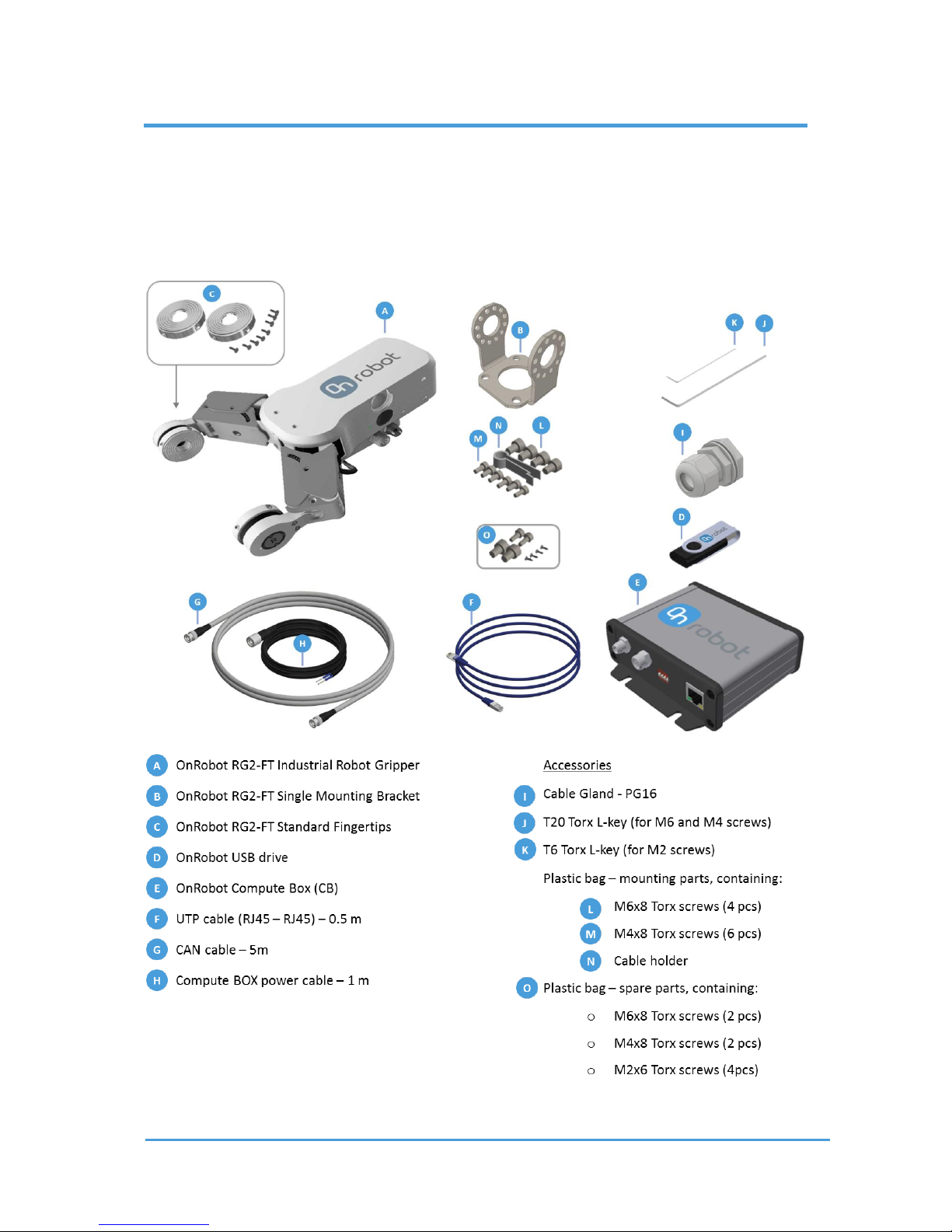
2.1 Scope of Delivery
In the Universal Robots OnRobot RG2-FT Gripper Kit everything is provided that is required
to connect the OnRobot gripper to your UR robot.
Page 10
Getting Started 10
OnRobot © 2018 www.onrobot.com
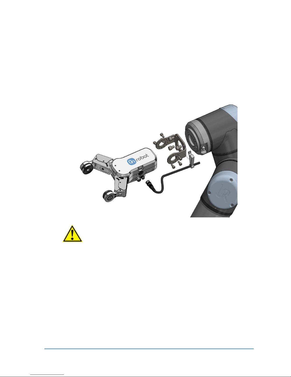
2.2 Mounting
Use only the screws provided with the gripper. Longer screws could damage the gripper or
the robot.
To mount the gripper, follow this process:
1. Fasten the Gripper bracket to the Robot by four M6x8 screws. Use 7 Nm tightening
torque. Use the T20 Torx L-key.
2. Fasten the Gripper to the adapter by six M4x8 screws. Use 2 Nm tightening torque.
Use the T20 Torx L-key.
CAUTION:
The design of the standard Gripper bracket allows the angle of the Gripper to
be adjusted from 0° to 180° in steps of 30°.
However, to ensure all software functions are work properly, mount the
gripper straight, exactly as you can see on the exploded view. Please also
note where the tool connector is relative to the gripper connector.
Page 11
Getting Started 11
OnRobot © 2018 www.onrobot.com
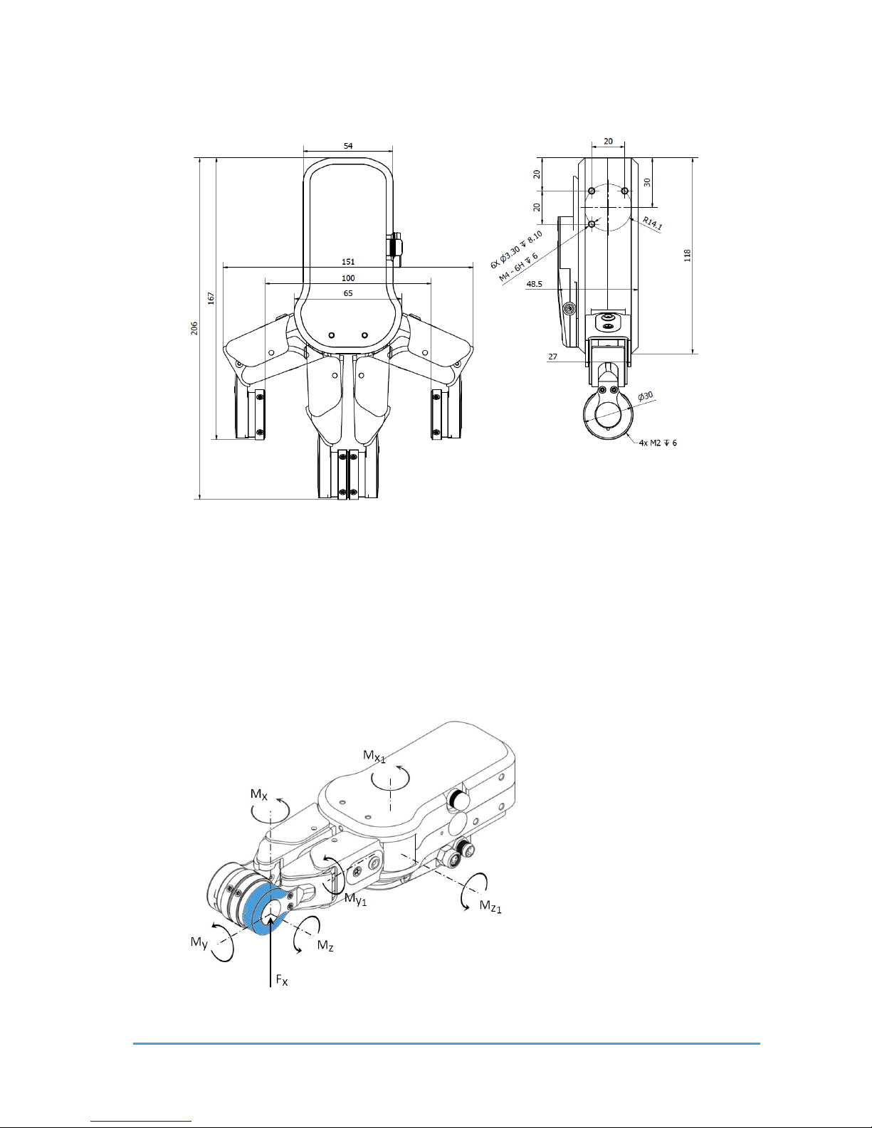
2.3 Mechanical Dimensions
The dimensions are in millimeters.
2.4 Load Capacity
2.4.1 G ripper Load
Be aware that when grasping on an object, some of the parameters below are not directly
aplicative, but can be used to calculate the load on the Gripper.
Page 12
Getting Started 12
OnRobot © 2018 www.onrobot.com
Parameter
Static
Unit
Fx
362
[N]
Mz
7,55
[Nm]
Mx
4,1
[Nm]
My
6,92
[Nm]
Mz1
22
[Nm]
Mx1
11
[Nm]
My1
22
[Nm]
The parameters in the fingertips are calculated at the shown position and will change in
relation to the finger positions.
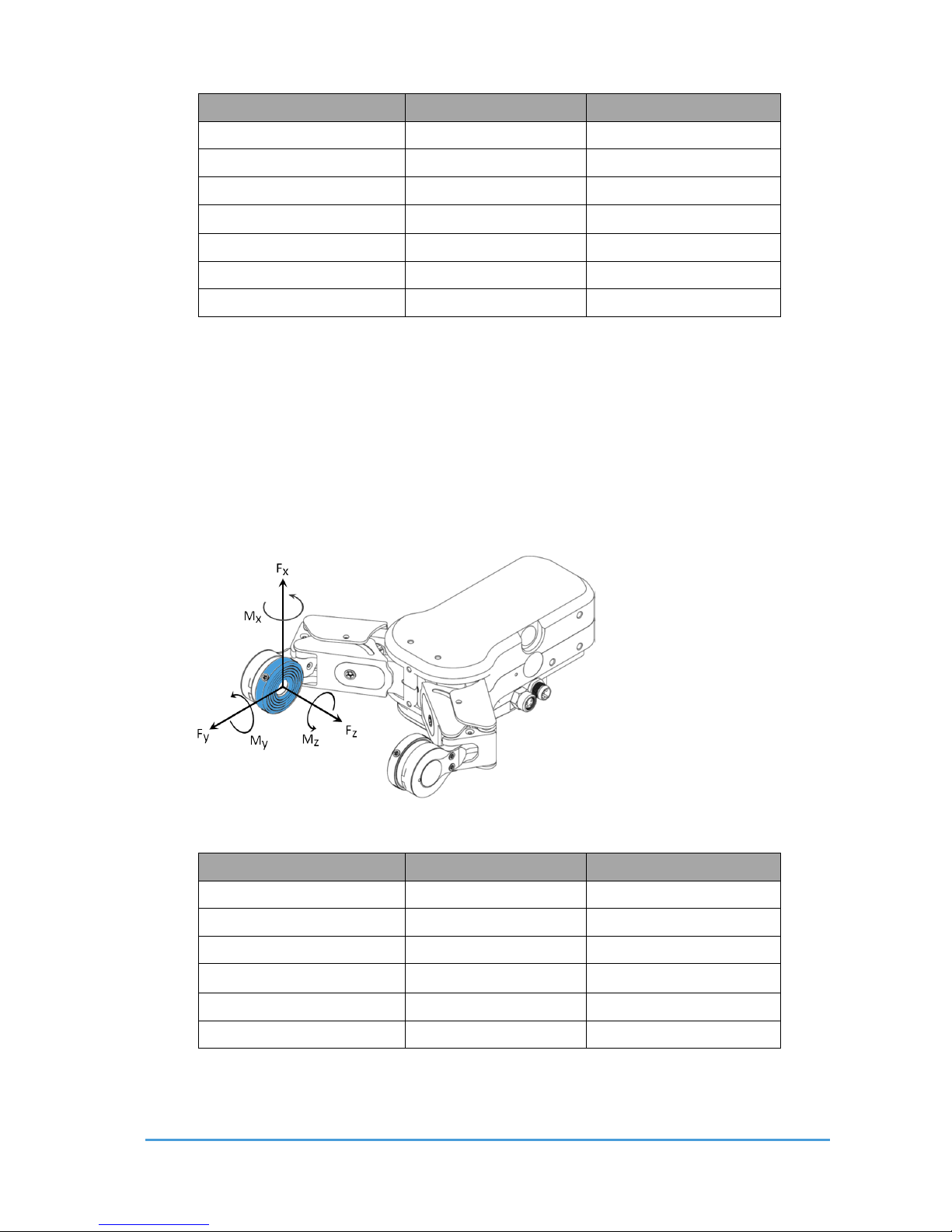
2.4.2 Finger Sensor L oad
The load that the gripper can handle is limited by the finger sensor. The actual object weight
that the gripper can lift may vary with the actual fingertips been used.
Parameter
Static
Unit
Fx
20
[N]
Fy
20
[N]
Fz
20
[N]
Mx
0.7
[Nm]
My
0.7
[Nm]
Mz
0.5
[Nm]
Page 13
Getting Started 13
OnRobot © 2018 www.onrobot.com
NOTE:
The black elastic ring of the finger sensor should not be loaded at all. If any
object contacts that part of the fingertips the sensor measurement will be
corrupted and therefore be avoided.
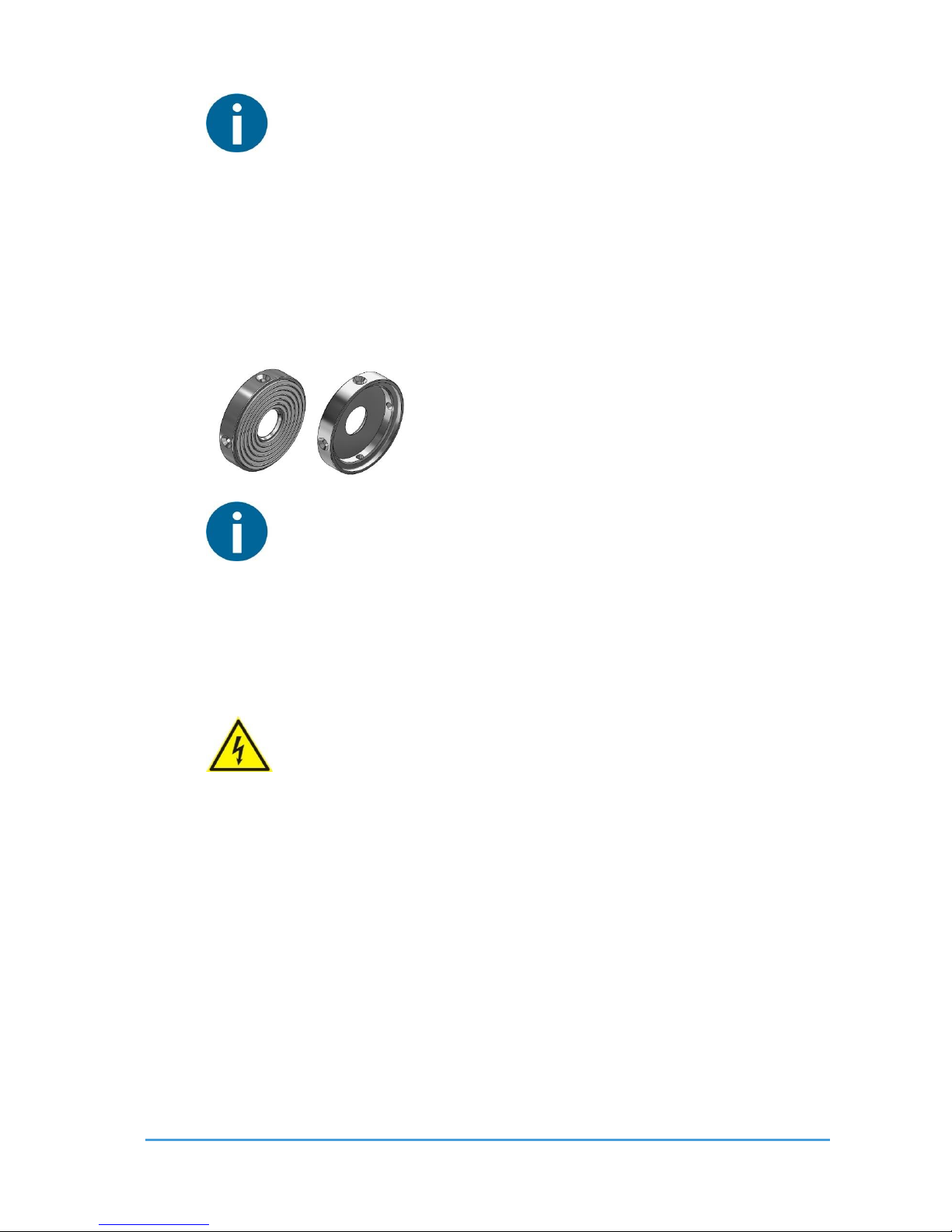
2.5 Fingertips
The standard fingertips can be used for many different workpieces. If custom fingertips are
required, they can be made to fit the Gripper fingers.
NOTE:
During the fingertip design, the following shall be considered to maintain
optimal performance:
- Clear optical path for the proximity sensors
- Protect the proximity sensors from direct sunlight or strong light
source
- Avoid dust and liquid penetration
WARNING:
The proximity sensors are sensitive parts and shall be protected against:
- Direct strong light (such as directional laser sources)
- Direct high temperature
- Mechanical contacts in any case
- Expose to any liquid or fine conductive dust
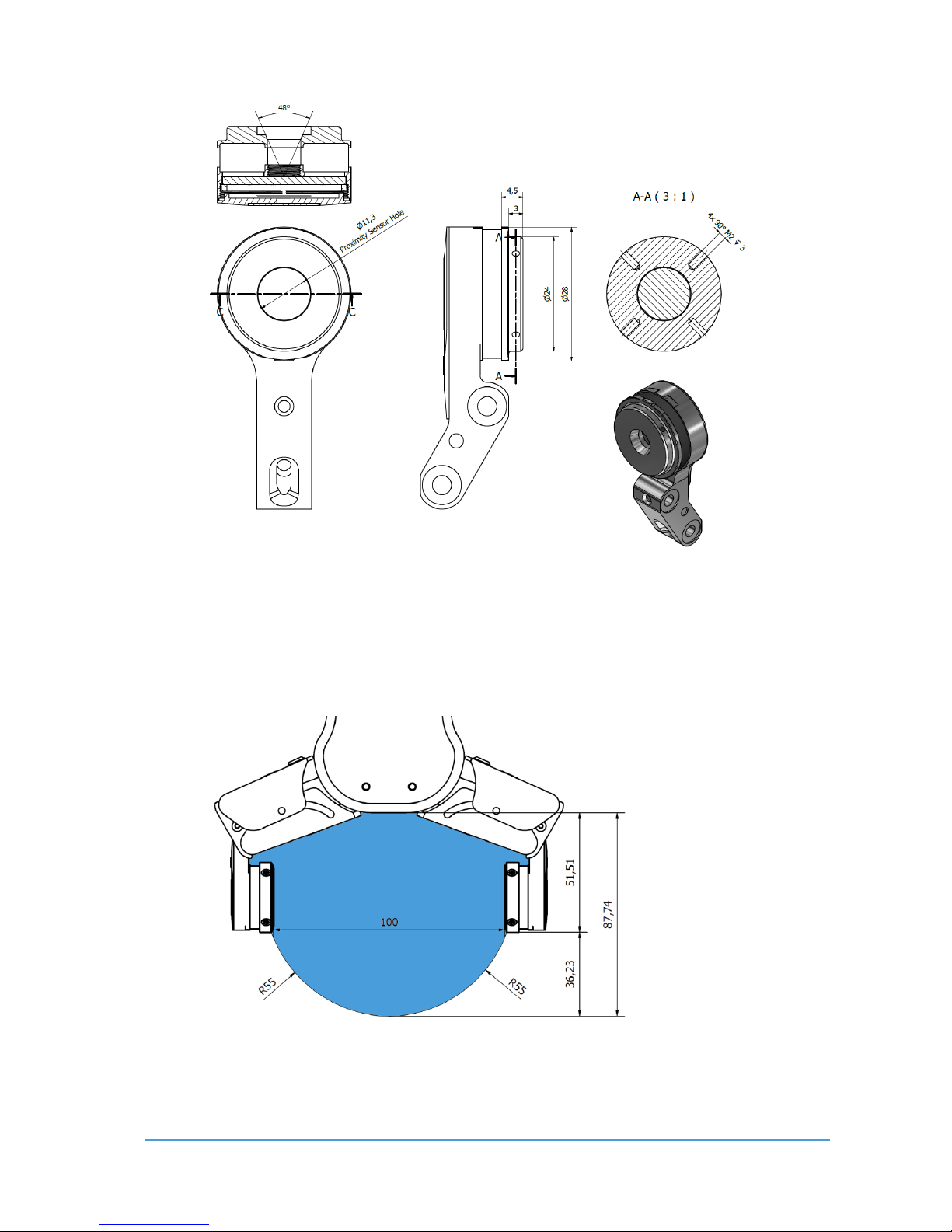
Dimensions of the Gripper’s finger, in millimeters.
Page 14
Getting Started 14
OnRobot © 2018 www.onrobot.com
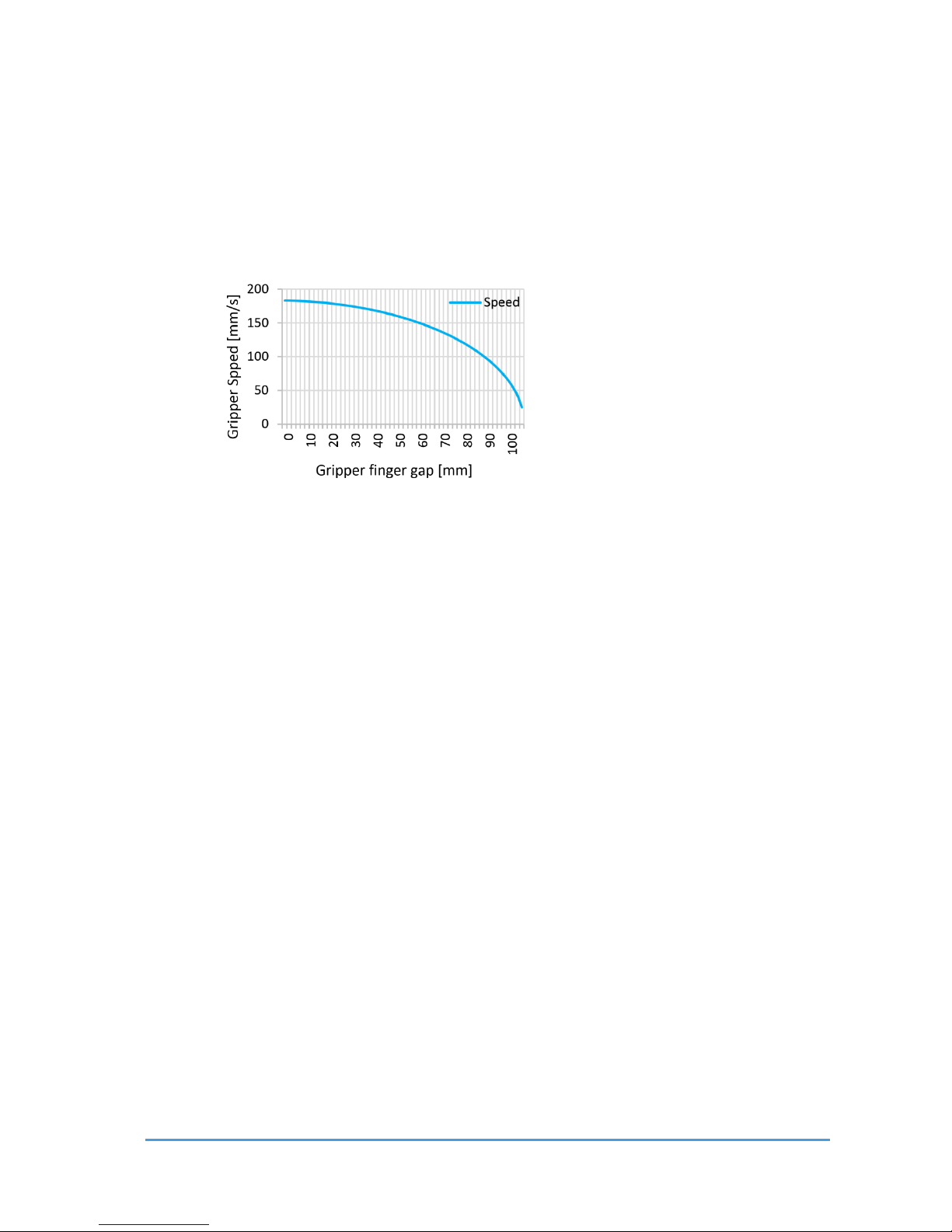
2.6 Gripper Working Range
The working range is measured between the fingers. See the figure below, for the gripper
working range.
The dimensions are in millimeters.
Page 15
Getting Started 15
OnRobot © 2018 www.onrobot.com
2.6.1 F inger Thi ckness
The default fingertips are considered while the finger thickness has been set and could not
be changed in the software. In case when custom fingertips are used, the user should
manually compensate for the difference in the finger thickness.
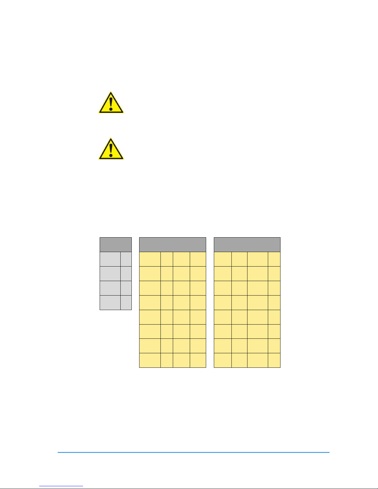
2.6.2 G ripping Speed
Speed table illustrating the difference in speed relative to the Gripper finger position.
Page 16
Getting Started 16
OnRobot © 2018 www.onrobot.com
2.7 Cable Conn ections
To connect the gripper, follow this process:
1. Connect the 4 pin M8 cable (5m long) to the gripper. Ensure that the holes of the
cable are aligned with the pins of the connector on the gripper.
CAUTION:
Do not rotate the cable, only rotate the connector lock.
2. Secure the cable to the robot with cable ties.
CAUTION:
Make sure that enough extra cable length is available around the joints for
bending.
3. Place the Compute Box somewhere near or inside the UR robot control cabinet and
connect the 4 pin M8 gripper cable. The provided cable gland can be used to lead
the cable into the UR Control cabinet.
4. Connect the Compute Box‘s Ethernet interface with the UR controller’s Ethernet
interface via the supplied UTP cable.
5. Use the 3 pin M8 cable (1m long) to power the Compute Box from the UR’s control
box. Connect the brown cable to the 24V and the black cable to the 0V.
Power
Configurable Inputs
Configurable Outputs
PWR
◼ 24V ◼ 24V ◼
0V ◼ OV ◼ GND
◼ CI0 ◼ CI4 ◼
CO0 ◼ CO4
◼
24V ◼
24V ◼ 24V ◼
0V ◼ 0V
◼
0V ◼
CI1 ◼ CI5 ◼
CO1 ◼ CO5
◼
24V ◼ 24V ◼
0V ◼ 0V
◼
CI2 ◼ CI6 ◼
CO2 ◼ CO6 ◼
24V ◼ 24V ◼
0V ◼ 0V
◼
CI3 ◼ CI7 ◼
CO3 ◼ CO7
◼
For more information, refer to the UR’s documentation.
6. Apply the correct network settings to both the Compute Box and the UR robot. The
default Compute Box IP address is 192.168.1.1, to change it, see Changing the IP of
the Compute Box.
Page 17
Getting Started 17
OnRobot © 2018 www.onrobot.com
2.8 UR Compatibility
The Gripper URCap plugins were developed and tested on UR version 3.6. If the UR version is
older than 3.6 it is recommended to upgrade the robot.
2.9 URCap Plugin Installation
To install the OnRobot URCap plugin, follow this process:
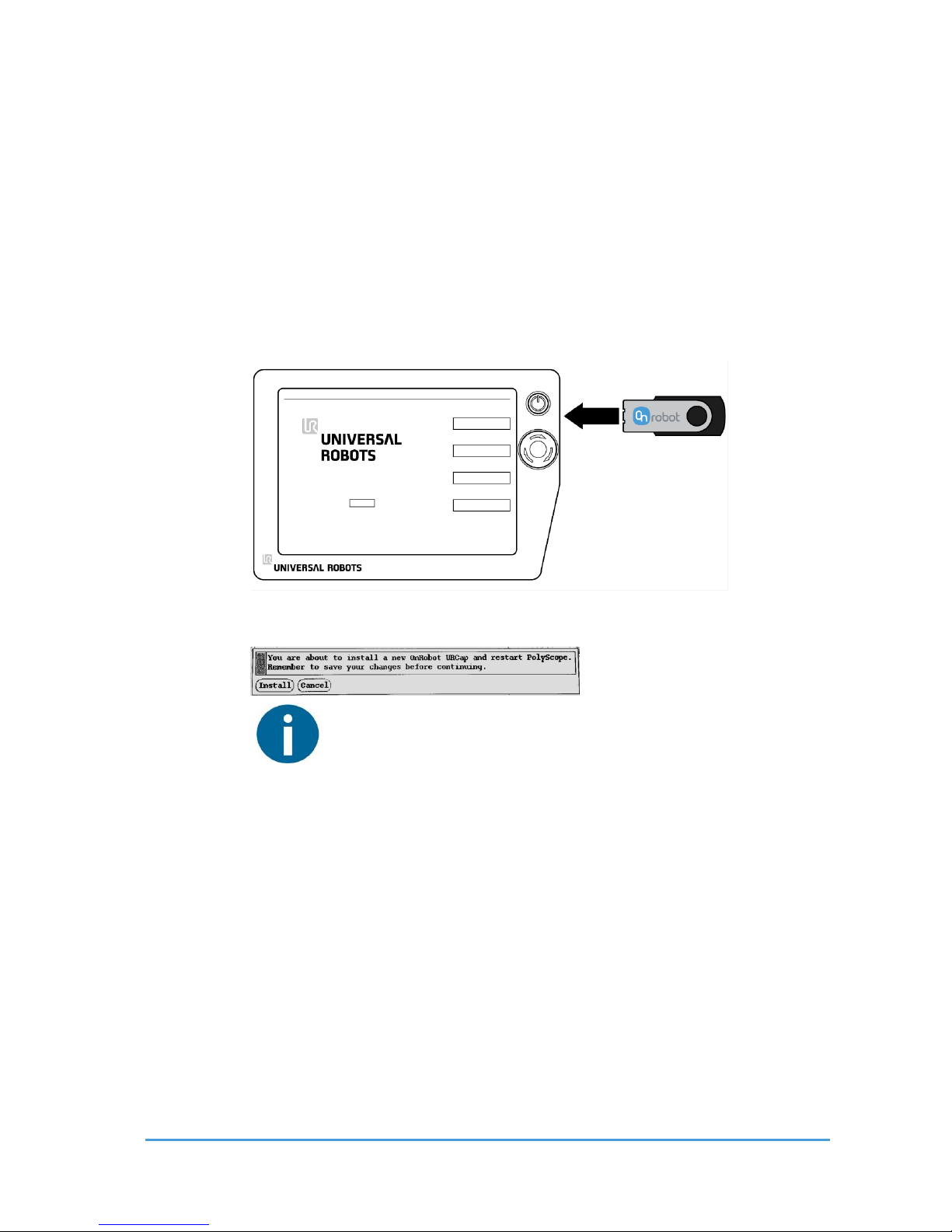
1. Insert the OnRobot USB drive in the USB slot on the right side of the Teach Pendant.
2. A message dialog window appears asking for your permission to continue with the
installation.
NOTE:
During the installation the robot controller will be automatically
restarted. Make sure no program is running or edited before
proceeding.
Tap on Install to continue
3. A progress bar appears, indicating the upload is in progress.
4. Wait for the robot to reboot.
5. Initialize the robot.
Continue with URCap Plugin Setup.
Page 18
Getting Started 18
OnRobot © 2018 www.onrobot.com
2.10 URC ap Plugin Setup
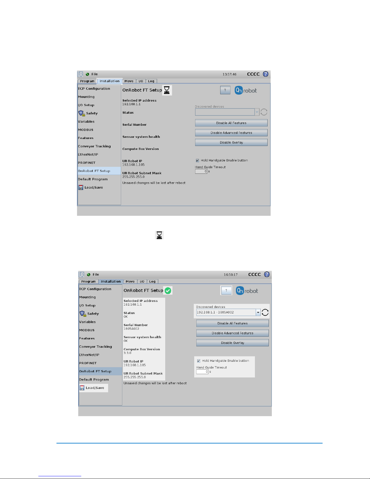
Select the Installation tab, then select OnRobot FT Setup. The following screen is shown:
Wait a few seconds while the software is automatically discovering the available OnRobot
RG2-FT devices. The hourglass icon indicates that the discovery is still in progress.
Once it finishes the first found device is selected and automatically tested, and the following
screen is shown:
Page 19

Getting Started 19
OnRobot © 2018 www.onrobot.com
The ok icon shows that the device is found, and the automatic test was successful, so
the device is ready to be used.
If no device is found or there was an error during the automatic test, then an error icon
is displayed. For troubleshooting URCap Plugin Setup error.
NOTE:
The discovery can be manually restarted by tapping on the refresh icon.
If multiple devices are available, the pre-selected device could be changed by
using the Discovered devices drop-down menu.
The status and basic information of the connected device is shown on the left:
Selected IP address: This shows the IP address of the selected device. Using the
factory default settings on the Compute Box the value will be 192.168.1.1.
Status: This shows OK or the error message in case of a malfunction.
Serial Number: The serial number of the RG2-FT.
Compute Box version: The software version of the Compute Box. This must match
the URCap version. If it does not match please update the Compute Box.
Status: This shows OK or in case of a malfunction it shows the error message.
The current network settings of the UR robot are showed to help the troubleshooting in case
of an error:
UR Robot IP: This shows the current IP address of the robot. Using the factory
default settings on the Compute Box the value must be 192.168.1.x.
UR Robot Subnet mask: The current subnet mask of the robot. Using the factory
default settings on the Compute Box the value must be 255.255.255.0.
The Hand Guide settings are in the bottom left:
Hold Handguide Enable checkbox: If checked (default value) the Hand Guide enable
button needs to be pressed constantly during the hand guiding. If unchecked, the
hand guiding could be started by tapping on the enable button and stopped by
tapping on the enable button again.
Hand Guide Timeout: After the set timeout value (in seconds) the hand guiding will
be stopped automatically. The default value is 0 that sets the timeout to infinite.
Page 20

Getting Started 20
OnRobot © 2018 www.onrobot.com
NOTE:
After setting up the device the changes need to be saved to be part of the
current installation with the Load/Save button.
For embedded help, tap on the question mark icon.
Page 21
Using the URCap Plugin 21
OnRobot © 2018 www.onrobot.com
3 Using the URCap Plugin
3.1 OnRobot Hand Guide Toolbar
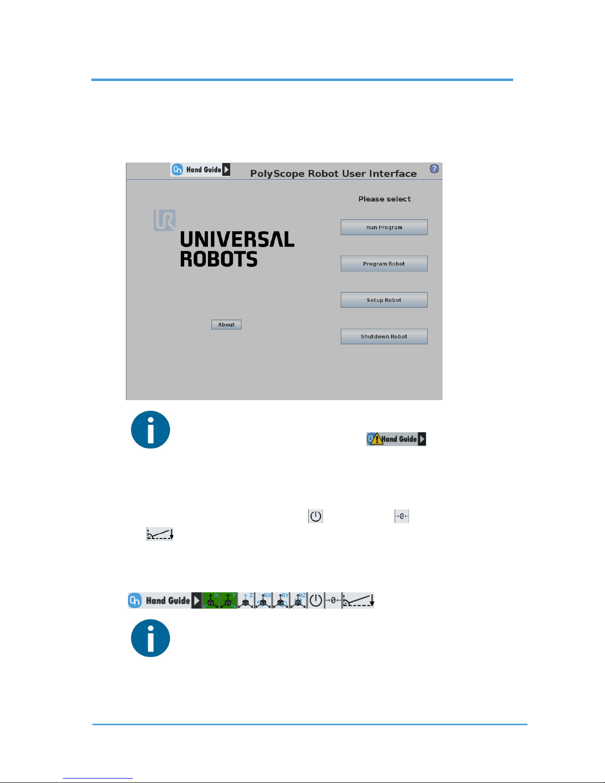
After turning on the UR robot, the start screen of the PolyScope is visible. After 20 seconds,
if it is activated, the OnRobot Hand Guide Toolbar appears on the top right.
NOTE:
It is normal to have a yellow warning signal during the bootup for a few seconds. If it does not disappear than check the device settings
at the URCap plugin setup.
To activate the functions of the toolbar, tap on any point of the toolbar. The toolbar
expands, and the available axes, the enable button, the zero button and the snap to
axes button will appear.
To select an axis, press the appropriate item. In the following example, the X and the Y items
are selected to limit the movement along the X and Y axis (planar):
NOTE:
The used coordinate system is the Tool.
To deactivate any axis that has been selected, press the item again.
Page 22
Using the URCap Plugin 22
OnRobot © 2018 www.onrobot.com
NOTE:
It is possible to activate or deactivate axes during hand guiding.
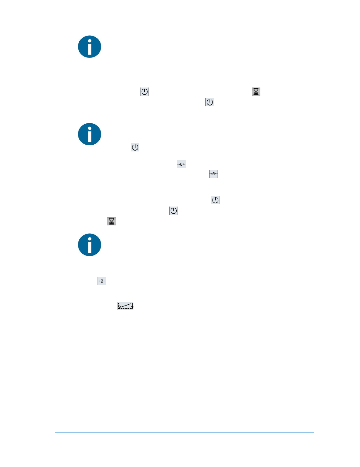
To start hand guiding the UR robot, first make sure that you do not touch the tool and then
press and hold the enable button. The button turns to an hourglass icon while the
hand guiding is being initiated. Wait until the enable button turns green and drive the
robot by hand with the help of the OnRobot finger sensor.
NOTE:
Make sure that you do not touch the tool before the hand guiding is activated
(enable button turned to green), otherwise the robot can behave
abnormally (e.g..: the robot could move without any external force exerted).
In this case, press the zero button, while you are not touching the tool.
Make sure that you do not use the zero button while touching the tool.
To stop hand guiding the UR Robot, release the enable button. Immediately after
deactivating hand guiding, the enable button is deactivated for 1 second, and turns into
an hourglass icon.
NOTE:
Please always set the speed slider of the robot to 100% while using the hand
guiding to have an optimal user experience.
The zero button is intended to be used when the tool orientation is changed during hand
guiding, so that the effects of gravity or changes in the load of the robot can be neutralized.
The snap to axes button rotates the axes of the tool coordinate system to align with
the closest axes of the base coordinate system, disregarding negative or positive directions.
This allows the user to set the tool to face precisely horizontally, or vertically, after guiding
by hand.
Page 23
Using the URCap Plugin 23
OnRobot © 2018 www.onrobot.com
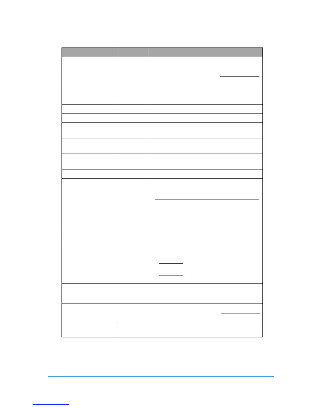
3.2 OnRobot Feedback Variables
Feedback Variable
Unit
Description
of_return
The return value for the OnRobot commands
rg_F3D_left
[N]
Length of the 3D force vector for the left finger
sensor rg_F3D_left=
rg_F3D_right
[N]
Length of the 3D force vector for the right finger
sensor rg_F3D_right=
rg_FT_left
[3xN,3xNm]
list of {Fx,Fy,Fz,Tx,Ty,Tz} for the left finger sensor
rg_FT_right
[3xN,3xNm]
list of {Fx,Fy,Fz,Tx,Ty,Tz} for the right finger sensor
rg_Grip_detected
True/False
True if Gripper has detected a work piece (must be
reset by the user)
rg_Grip_lost
True/False
True if Gripper has dropped a work piece (must be
reset by the user)
rg_Gripped
True/False
The actual status whether a workpiece has been
gripped or not
rg_Gyro
[3 x m/s2]
Reserved for further use
rg_Part_weight
[N]
The actual value of the detected part weight in N
rg_Part_weight =
rg_part_width
[mm]
The actual value of the detected part width (-1 if it
not applicable)
rg_Prox_left
[mm]
The left proximity (distance) sensor actual value
rg_Prox_right
[mm]
The right proximity (distance) sensor actual value
rg_Slip_alert
True/False
This goes True if the part will possible slip out of
the gripper. rg_Slip_alert =
or
rg_T3D_left
[Nm]
Length of the 3D torque vector for the right finger
sensor rg_T3D_left=
rg_T3D_right
[Nm]
Length of the 3D torque vector for the right finger
sensor rg_T3D_right=
rg_Width
[mm]
Distance between the fingers of the Gripper
(calculated by finger angle encoders)
Page 24

Using the URCap Plugin 24
OnRobot © 2018 www.onrobot.com
3.3 OnRobot URC ap Commands
These commands can be used to create complex pick and place and assembly applications
easily with the help of the RG2-FT gripper.
In the next sub-sections each of these commands will be described.
NOTE:
For embedded help, tap on the question mark icon within each
command.
3.3.1 F/T W i dth
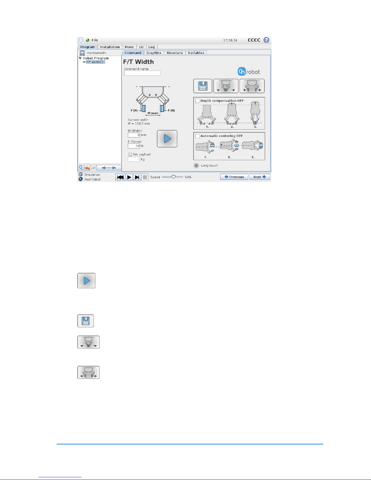
The F/T Width command controls the width of the gripper. It can open or close the gripper
to a given width or a given force. It has advanced features like depth compensation and
automatic centering.
NOTE:
To cancel any force/torque offset, execute an F/T Zero command at the
beginning of the F/T Width command and make sure the tool is not in
contact with any object before starting the F/T Width, otherwise the
command may not work properly.
NOTE:
To cancel any distance offset of the optical finger sensors, make sure to carry
out the steps written in the Zero the optical offset sub-section, otherwise
the command may not work properly.
Page 25
Using the URCap Plugin 25
OnRobot © 2018 www.onrobot.com
Current width W=…: the current width of the gripper.
W (Width): Enter the desired gripper width. Note that if the specified force is achieved, the
RG2-FT will stop at a width that differs from the target width.
F (Force): Enter the desired gripping force. Note that if the target width is reached before
the target force, the RG2-FT will stop moving and the target force may not be achieved at
the anticipated width.
Set Payload checkbox: if checked, the UR payload settings are overridden by the given value.
Execute button: executes the command with its current settings, without running
the entire Program. Note that the button needs to be pressed (Long touch) continuously to
operate.
Copy button: Copy the current width value to the desired W(width) edit box.
Open gripper button: hold the button to open the gripper. Can be stopped at any
position.
Close gripper button: hold the button to close the gripper. Can be stopped at any
position.
Page 26
Using the URCap Plugin 26
OnRobot © 2018 www.onrobot.com
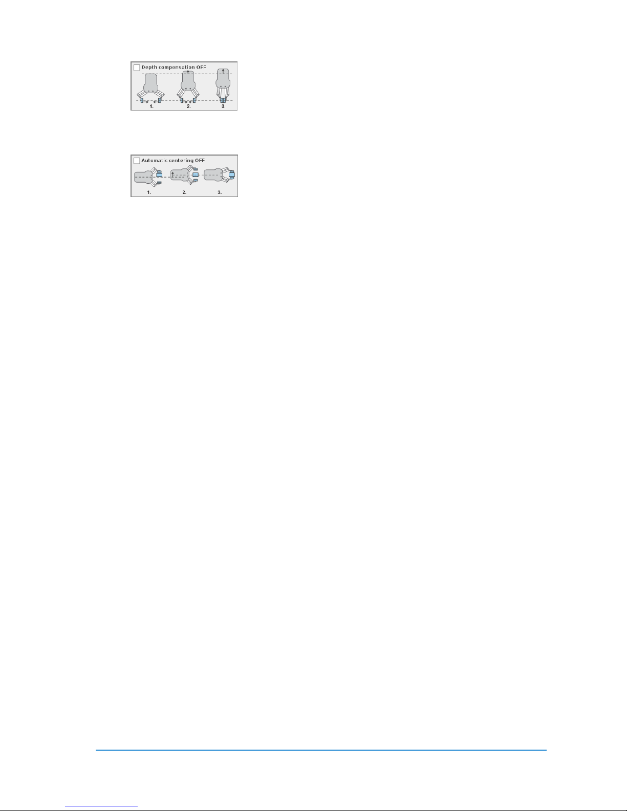
Depth Compensation checkbox: if checked, during closing and
opening the gripper, the robot moves to compensate the movement of the fingertips so that
it remains on the target.
Automatic Centering checkbox: if checked, during closing and
opening the gripper, the robot moves the gripper sideways to grab the item symmetrically
based on the proximity signals of the fingers.
For return values, see F/T Width Command Return Values.
Page 27
Using the URCap Plugin 27
OnRobot © 2018 www.onrobot.com
3.3.2 F /T Set Load
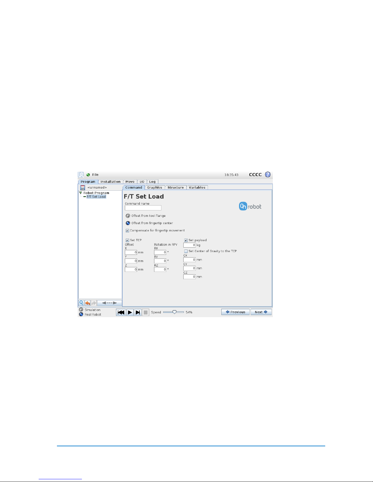
The F/T Set Load command can be used to set a new payload and to change the TCP
settings within one command.
The TCP settings can be given in two ways:
Offset from tool flange: the TCP offsets is given relative to the tool flange
Offset from fingertip center: the TCP offsets is given relative to the middle of the
fingertips center line. Choosing this way, the following option will become visible:
Compensate for fingertip movement: If checked the offset origin is changed
when the fingertip moves
Either the TCP or the Payload needs to be checked to be set to enable the command to be
executed.
Set TCP offset checkbox: if checked, the installation TCP settings will be overridden with the
given values.
Offset X, Y, Z: the translation values of the TCP relative to the tool flange (or the
fingertip center).
Rotation in RPY RX, RY, RZ: the rotational values of the TCP relative to the tool flange
(or the fingertip center).
Set payload checkbox: if checked, the installation Payload and Center of Gravity settings will
be overridden with the given values. The payload must be the overall weight, including the
gripper.
Page 28
Using the URCap Plugin 28
OnRobot © 2018 www.onrobot.com
CX, CY, CZ: the coordinates of the Center of Gravity in relation to the tool flange (or the
fingertip center).
Set Center of Gravity to the TCP checkbox: if checked, CX,CY,CZ values are given by the
set TCP offset.
This command has no return value.
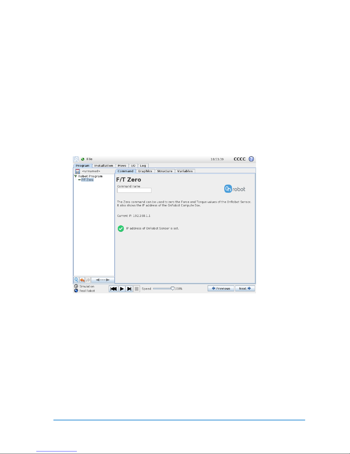
3.3.3 F/T Zero
The F/T Zero command can be used to zero the RG2-FT finger sensor force/torque
values.
This command has no return value.
Page 29
Using the URCap Plugin 29
OnRobot © 2018 www.onrobot.com
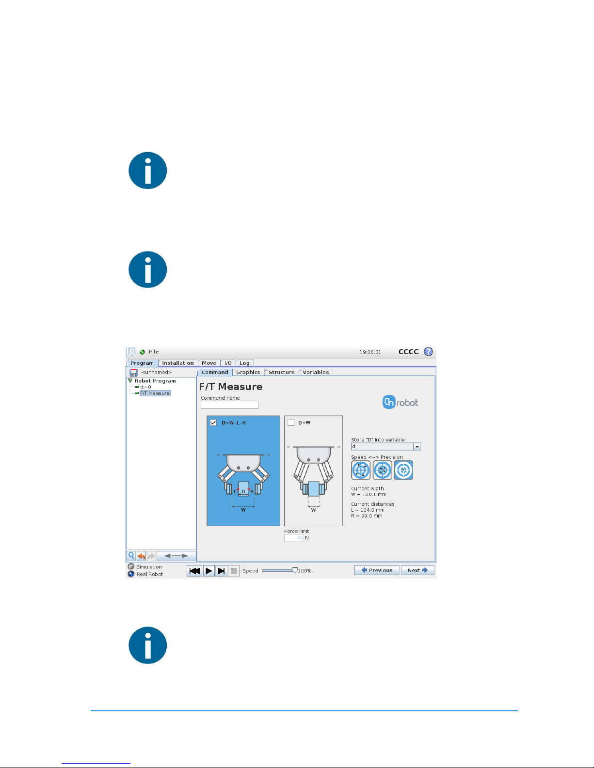
3.3.4 F/T Measure
The F/T Measure command can be used to measure a part placed between the fingers and
store this information into a variable.
The measurement will give a cross-section width of the part. There are two ways to carry out
the measurement either optically or touch based.
NOTE:
To cancel any force/torque offset, execute an F/T Zero command at the
beginning of the F/T Measure command and make sure the tool is not in
contact with any object before starting the F/T Measure, otherwise the
command may not work properly.
NOTE:
To cancel any distance offset of the optical finger sensors, make sure to carry
out the steps written in the Zero the optical offset sub-section, otherwise
the command may not work properly.
Optical measurement (D=W-L-R) checkbox: if checked, the measurement is based on the
width of the gripper and the optical sensor, without touching the part.
NOTE:
The measurement result (D) will be -1 if no object is placed between the
fingers.
Page 30

Using the URCap Plugin 30
OnRobot © 2018 www.onrobot.com
Force measurement (D=W) checkbox: if checked, the measurement is based on the width of
the gripper when it has grabbed the part. The part is grabbed when the set force value has
reached.
Force Limit: the set force value to be used to detect when a part is grabbed
Store “D” into variable dropdown list: an already existing variable can be selected, where
the measured distance will be saved at the end of the measurement. The variable needs to
be created first, by using an Assignment UR command. For further help on creating a
variable refer to the UR Manual.
Speed <--> Precision selector buttons: the measurement precision can be selected.
Current Width W=: the current width of the gripper.
Current distances L, R: the current distance measured by the left and right side optical
sensors.
This command has no return value.
Page 31
Using the URCap Plugin 31
OnRobot © 2018 www.onrobot.com
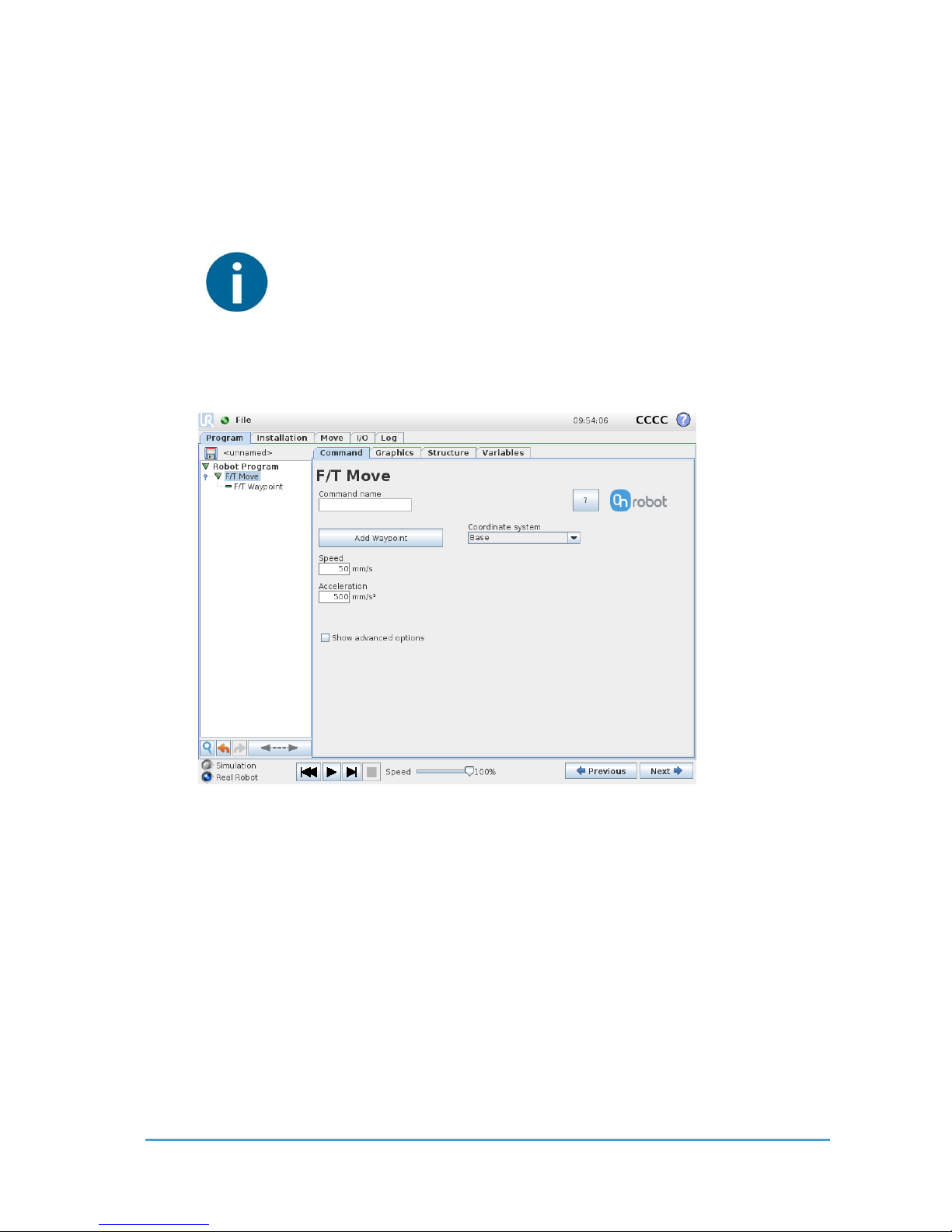
3.3.5 F /T Mov e
The F/T Move command can be used together with the F/T Waypoint command, to
move the robot along a route, or together with the F/T Path to move the robot along a
path and stop once the defined force/torque limits are reached (movement interrupted). In
this case a warning can be generated. If the movement reaches the last waypoint, the move
is successful.
NOTE:
To cancel any force/torque offset, execute an F/T Zero command at the
beginning of the F/T Move command and make sure the tool is not in
contact with any object before starting the F/T Move, otherwise the
command may not stop at the given force/torque limit.
To operate the F/T Move command tap on the Add Waypoint button to add an F/T
Waypoint as a child node. More waypoints can be added in the same way. To remove a
waypoint, use the Structure tab Delete button.
Alternatively, F/T Waypoint or F/T Path could be added as a child node of the F/T
Move command by using the Structure tab.
Speed: The movement speed limit while moving. The movement is carried out in a constant
translational speed. If the route or path has sharp changes in the direction, or the
orientation, the actual speed of the robot may be less than specified, but still constant
throughout the route or Path.
Acceleration: The acceleration and deceleration parameter of the movement.
Page 32
Using the URCap Plugin 32
OnRobot © 2018 www.onrobot.com
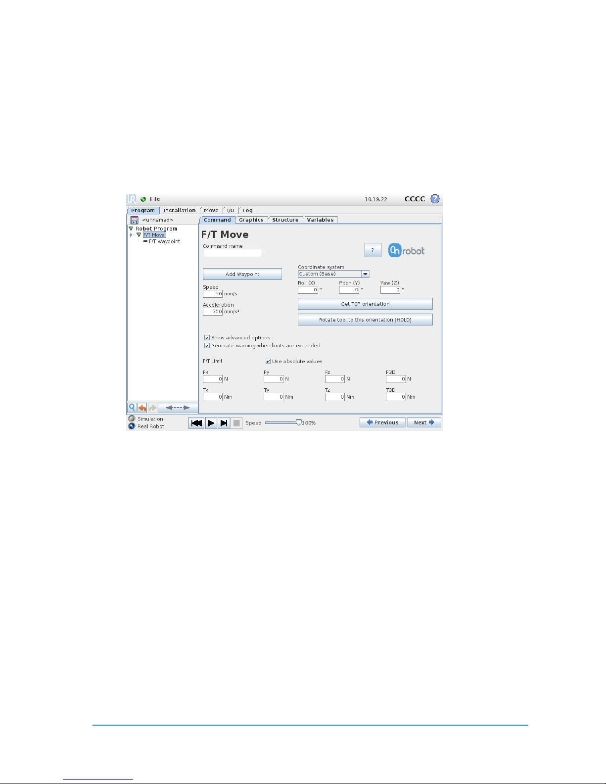
Coordinate system: The coordinate system used both for the movement and for the sensor
reading. It can be set to Base, Tool, Custom (Base) Custom (Tool) (according
to the UR’s reference frames). The Custom coordinate systems are calculated from the basis
coordinate system and the given Roll, Pitch and Yaw values. For the Custom (Base)
coordinate system, it is also possible to use the Get TCP orientation button to specify the
orientation of the coordinate system, by the orientation of the current TCP. To test the given
orientation, the Rotate tool to this orientation [HOLD] button can be used.
Show advanced options checkbox: If checked then more options become available:
F/T Limit Fx,Fy,Fz,Tx,Ty,Tz,F3D,T3D: This is the detection limit. From the Fx, Fy, Fz, Tx, Ty, Tz,
F3D, T3D available options more than one can be set. In this case, if any of the values reach
the set threshold the stop is triggered. Values equal to zero are neglected.
If the Use absolute values option is enabled, then it is not important whether the
entered value is positive or negative (e.g.: |Fz| > = 3), otherwise the sign defines
how the threshold is calculated (e.g.: Fz > = 3 or Fz <= -3)
Generate warning (…): If enabled then a pop-up message (blocking) appears if the
target position is not reached (the move is not successful). If the move is successful,
then no warning is displayed.
If disabled, then no pop-up message is shown but the user can handle any possible
errors by the return value of the command.
For return values, see F/T Move Command Return Values.
Page 33
Using the URCap Plugin 33
OnRobot © 2018 www.onrobot.com
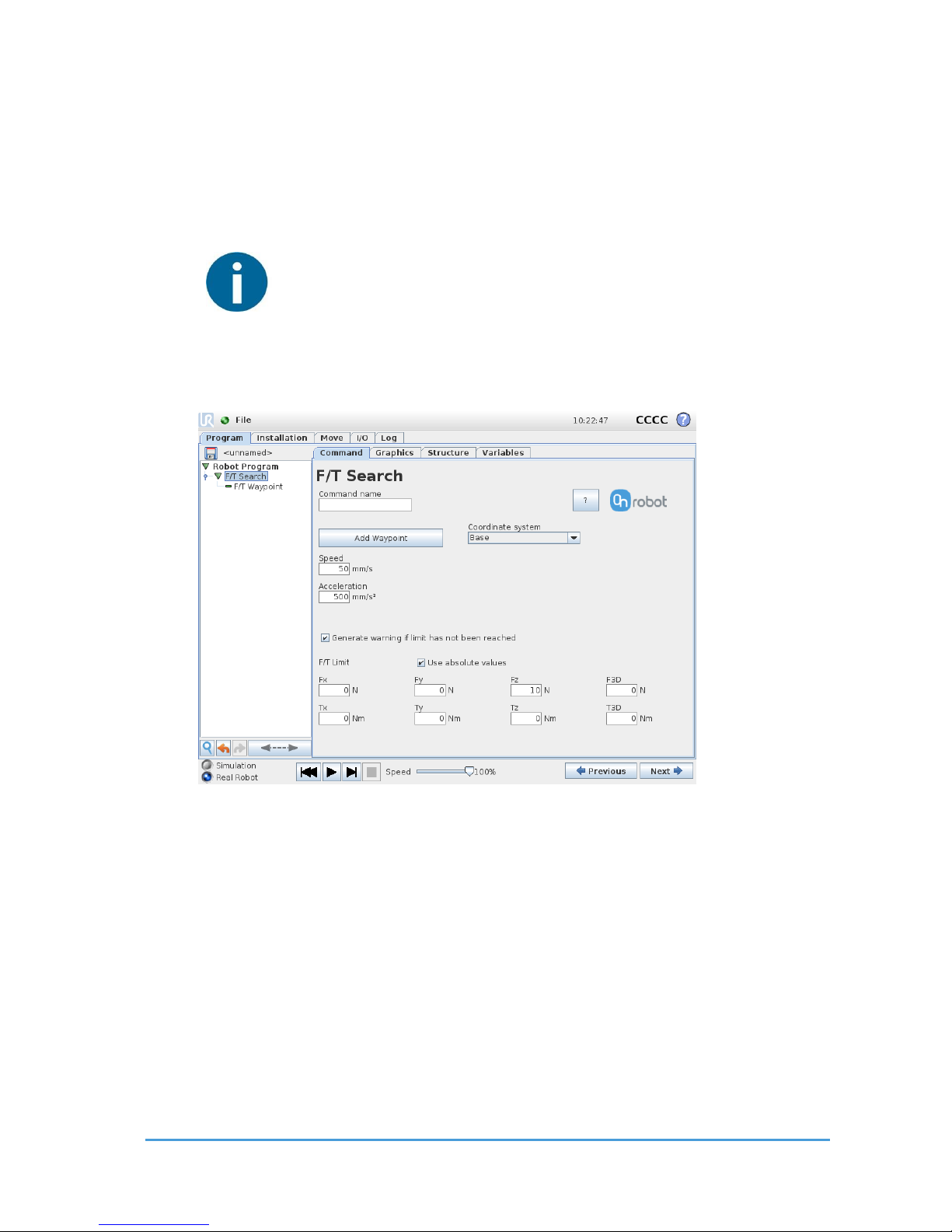
3.3.6 F /T Sea rch
The F/T Search command is used together with the F/T Waypoint command, to
move the robot along a route, or together with the F/T Path to move the robot along a
Path and stop once the defined force/torque limits are reached (object found). If the
movement reaches the last waypoint or the last point of the path, the search is not
successful (the object is not found) and a warning is generated.
NOTE:
To cancel any force/torque offset, execute an F/T Zero command at the
beginning of the F/T Search command and make sure the tool is not in
contact with any object before starting the F/T Search, otherwise the
command may not stop at the given force/torque limit.
To operate the F/T Search command tap on the Add Waypoint button to add an F/T
Waypoint as a child node. More waypoints can be added in the same way. To remove a
waypoint, use the Structure tab Delete button.
Alternatively, F/T Waypoint or F/T Path could be added as a child node of the F/T
Search command by using the Structure tab.
Speed: The movement speed while searching for collision. The movement is carried out in a
constant translational speed. If the route or path has sharp changes in the direction, or the
orientation, the actual speed of the robot may be less than specified, but still constant
throughout the route or Path.
Page 34

Using the URCap Plugin 34
OnRobot © 2018 www.onrobot.com
NOTE:
The slower the speed during the searching phase is the better to work with
hard contacts (such as metal surfaces) to avoid overshoots due to the robot’s
and the tool's momentum.
Acceleration.: The acceleration and deceleration parameter of the movement.
F/T Limit Fx,Fy,Fz,Tx,Ty,Tz,F3D,T3D: This is the detection limit. From the Fx, Fy, Fz, Tx, Ty, Tz,
F3D, T3D available options more than one can be set. In this case, if any of the values reach
the set threshold the stop is triggered. Values equal to zero are neglected.
If the Use absolute values option is enabled, then it is not important whether the
entered value is positive or negative (e.g.: |Fz| > = 3), otherwise the sign defines how
the threshold is calculated (e.g.: Fz > = 3 or Fz <= -3)
Coordinate system: The coordinate system used both for the movement and for the sensor
reading. It can be set to Base, Tool, Custom (Base) Custom (Tool) (according
to the UR’s reference frames). The Custom coordinate systems are calculated from the basis
coordinate system and the given Roll, Pitch and Yaw values. For the Custom (Base)
coordinate system, it is also possible to use the Get TCP orientation button to specify the
orientation of the coordinate system, by the orientation of the current TCP. To test the given
orientation, the Rotate tool to this orientation [HOLD] button can be used.
Generate warning (…): If enabled then a pop-up message (blocking) appears once the
target position is reached or was already in collision (so the search is not successful. If the
search is successful, then no warning is displayed.
If disabled, then no pop-up message is shown but the user can handle any possible errors by
the return value of the command.
For return values, see F/T Search Command Return Values.
Page 35
Using the URCap Plugin 35
OnRobot © 2018 www.onrobot.com
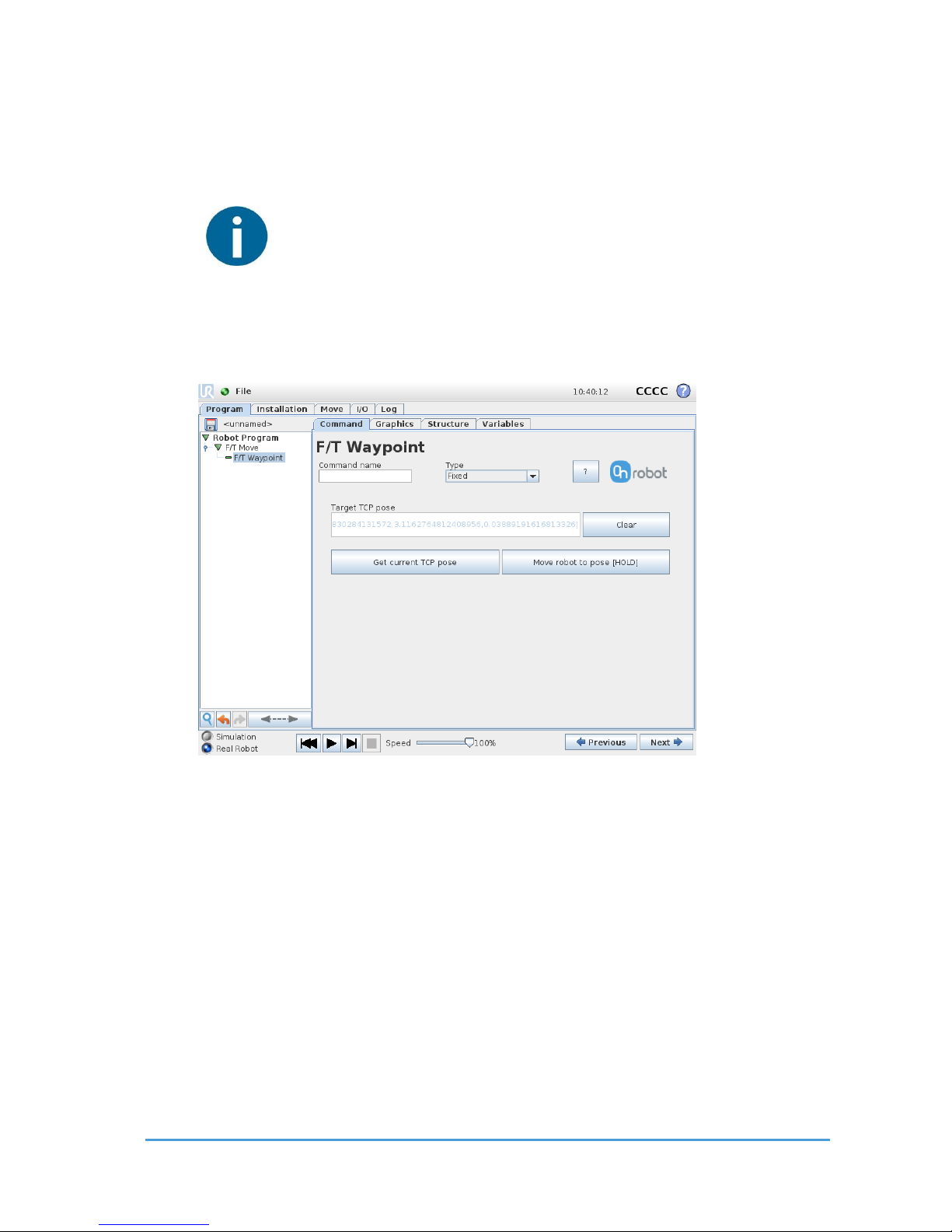
3.3.7 F/T W a ypoint
The F/T Waypoint command is used together with the F/T Move or F/T Search
command, to move the robot along a route. There are three types of waypoints (Fixed,
Relative, and Variable), that can be used in any combination.
NOTE:
Do not use consecutive F/T Waypoints that only contain rotations in the
same F/T Move command. Use more than one F/T Move commands to
achieve rotations without translational movements.
Waypoint type: The type of the waypoint. It can be set to Fixed, Relative or
Variable.
Target TCP pose: The position represented by the waypoint in the robot route. It is a readonly field and can be filled by using the Get current TCP pose button.
Clear button: deletes the contents of the Target TCP pose field.
Get current TCP pose button: inserts the current TCP coordinates into the Target TCP pose
field.
Move robot to pose [HOLD] button: moves the robot to the pose set in the Target TCP pose
field, if the button is pressed. Once it is released the robot stops.
Page 36
Using the URCap Plugin 36
OnRobot © 2018 www.onrobot.com
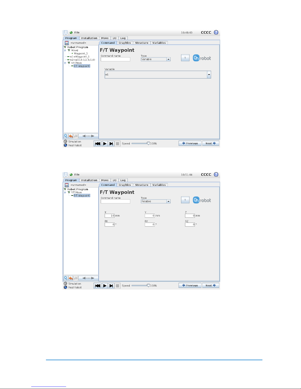
Variable: The position represented by the waypoint in the robot route. A variable can define
the target pose. The variable needs to created first.
Relative X, Y, Z, RX, RY, RZ: the distances and rotations this waypoint represents, compared
to the previous robot position.
This command has no return value.
Page 37
Using the URCap Plugin 37
OnRobot © 2018 www.onrobot.com
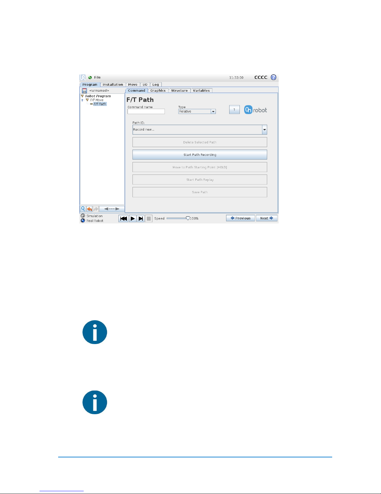
3.3.8 F /T Pat h
The F/T Path command can be used together with the F/T Move or F/T Search
command, to record and replay a Path.
Type: If relative is selected, the Path is replayed starting from the actual position of the Tool,
instead of the absolute position where it was recorded. If absolute is selected, the Tool
moves to the original starting point, and replays the Path from there.
Path ID dropdown list: Lists identifiers of all the Paths saved on the Compute Box. A Path ID
is assigned to a path, when the path is saved. If there is no recorded unsaved path, there is a
Record new… item, select it to record a new path. If there is a recorded Path that is not
saved, there is an Unsaved item in the List.
NOTE:
Only one unsaved Path can exist, and it will be overwritten by starting a Path
recording while the Unsaved Path is selected.
Delete Selected Path button: Deletes the path currently selected in the Path ID dropdown
list from the Compute Box, permanently.
NOTE:
Do not delete a Path that any other F/T Path commands is using.
.
Page 38
Using the URCap Plugin 38
OnRobot © 2018 www.onrobot.com
Start Path Recording button: Starts recording a Path by automatically enabling the Hand
Guide function.
Stop Path Recording button: Stops the Hand Guide function and stores the recording to the
memory. It does not permanently save the Path.
Move to Path Starting Point [HOLD] button: moves the Tool to the starting position of the
Path, it can only be used if the path is not relative.
Start Path Replay button: Replays the Path, even if it is not saved, only stored in the
memory.
Stop Path Replay button: Stops replaying the Path.
Save Path button: Saves the Unsaved Path to the Compute Box.
NOTE:
Rotational movements related to translational movements in Path recording
are limited to 2.8 degrees/mm or less, since a larger ratio would cause the
Robot to replay the path at a very low translational speed. Rotational
movement without translational movement therefore cannot be recorded as
Path.
NOTE:
The maximum error of the replayed Path compared to the original recorded
movement can be up to 1 mm.
This command has no return value.
Page 39
Using the URCap Plugin 39
OnRobot © 2018 www.onrobot.com
3.3.9 F/T D etect
The F/T Detect command can be used to find a part, together with the F/T Move, F/T
Search or F/T Path commands.
NOTE:
To cancel any force/torque offset, execute an F/T Zero command at the
beginning of the F/T Detect command and make sure the tool is not in
contact with any object before starting the F/T Detect, otherwise the
command may not work properly.
NOTE:
To cancel any distance offset of the optical finger sensors, make sure to carry
out the steps written in the Zero the optical offset sub-section, otherwise
the command may not work properly.
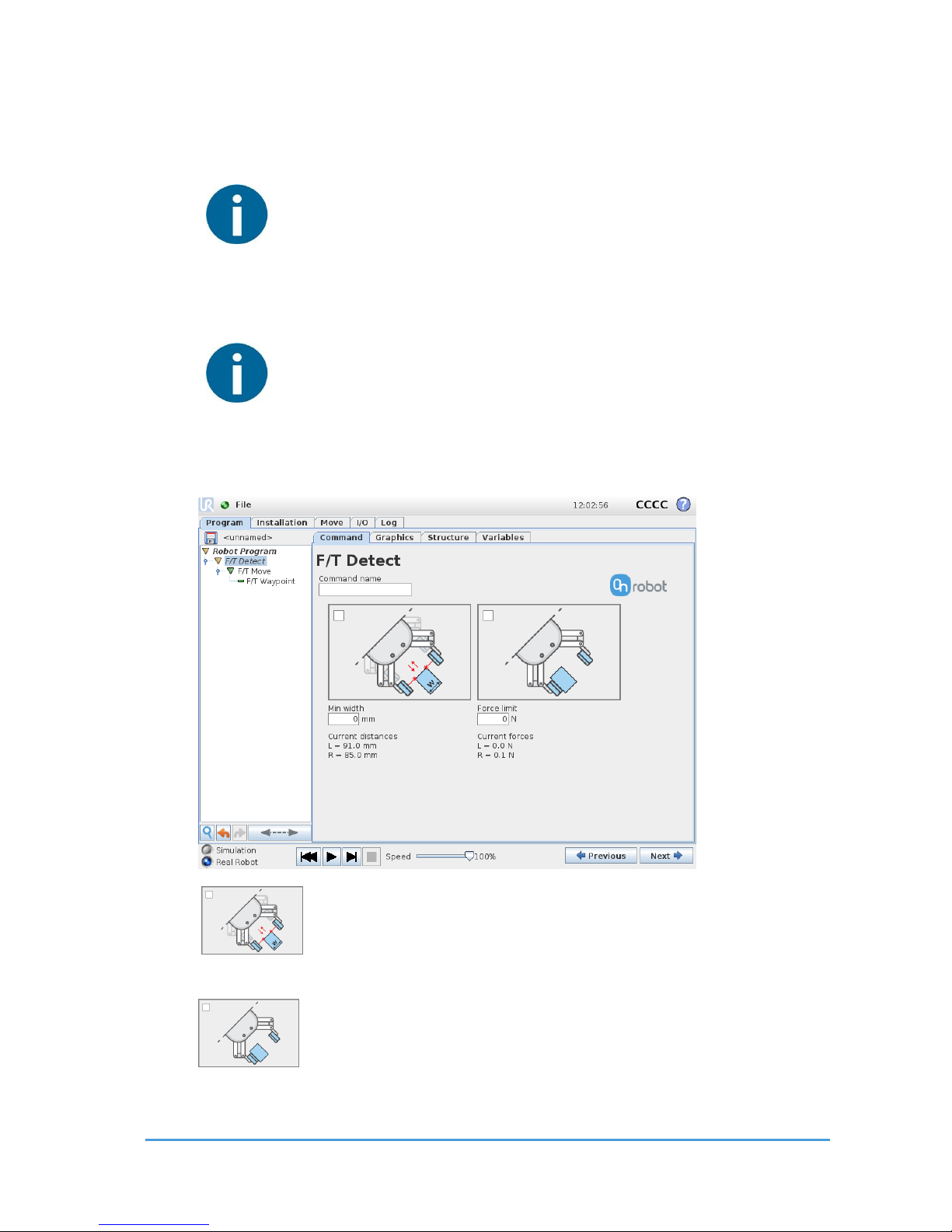
Optical Detection checkbox: if checked, the optical sensor is used to detect
the item.
Force Detection checkbox: if checked, the force torque sensor is used to
detect the item.
Page 40

Using the URCap Plugin 40
OnRobot © 2018 www.onrobot.com
Min width: Items with less size are ignored.
Depending on the shape and orientation, an item with greater size
than the maximum width can trigger the part detect command.
Force Limit: The amount of force needed to consider a part detected.
Current distances L, R: the current distance measured by the left and right side optical
sensors.
Current forces L, R: the current overall force (F3D) measured by the left and right-side force
sensors.
For return values, see F/T Detect Command Return Values.
Page 41
Using the URCap Plugin 41
OnRobot © 2018 www.onrobot.com
3.3 . 10 F/T I nsert P a rt
The F/T Insert Part command can be used for precision fitting an object into a hole.
NOTE:
To cancel any force/torque offset, execute an F/T Zero command at the
beginning of the F/T Insert Part command and make sure the tool is
not in contact with any object before starting the F/T Insert Part,
otherwise the command may not stop at the given force/torque limit.
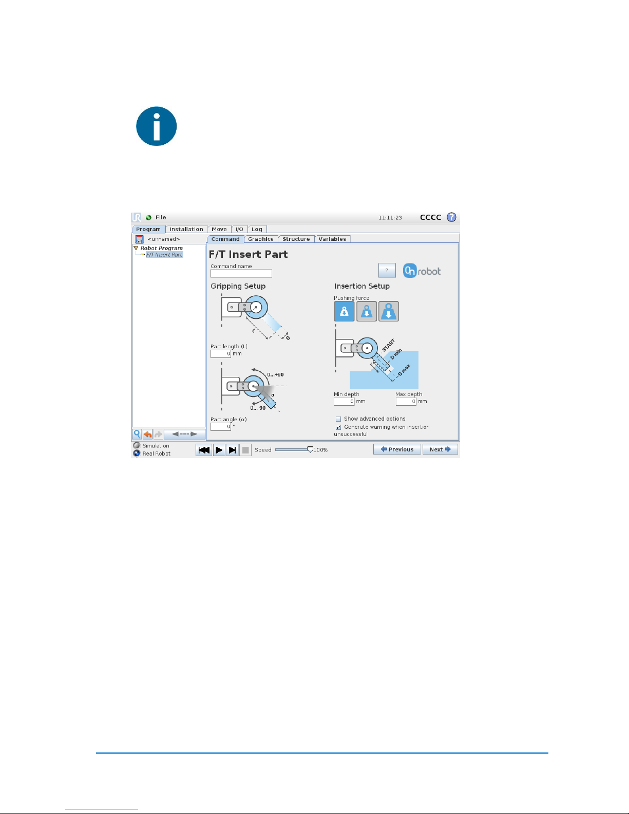
Part Length (L): the distance between the center point of the fingertip sensors and the
center point of the item to be inserted.
Part angle (α): the angle between the +Y axis of the fingertip sensor and the insertion
direction of the item to be inserted.
Pushing Force buttons: the pushing force can be selected:
Low Pushing Force button: sets the pushing force to be 3N.
Middle Pushing Force button: sets the pushing force to be 6N.
High Pushing Force button: sets the pushing force to be 12N.
Min depth: The minimum distance required to consider the insertion successful, from the
starting point.
Max depth: The maximum distance the insertion can reach, from the starting point.
Show advanced parameters checkbox: If checked, more options become available:
Page 42
Using the URCap Plugin 42
OnRobot © 2018 www.onrobot.com
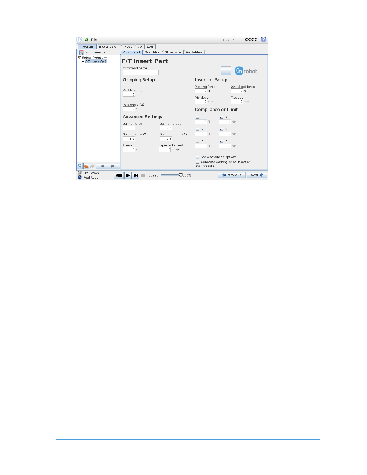
Part Length (L): the distance between the center point of the fingertip sensors and the
center point of the item to be inserted.
Part angle (α): the angle between the +Y axis of the fingertip sensor and the insertion
direction of the item to be inserted.
Gain of force: The proportional gain parameter of the force control for the side forces on
compliant axes.
Gain of torque: The proportional gain parameter of the torque control for the compliant
axes.
Gain of force (Z): The proportional gain parameter of the force control for the pushing force.
Gain of torque (Z): The proportional gain parameter of the torque control parallel to the
insertion direction.
Timeout: The maximal allowed time for the whole insertion function. If it is set to zero, this
exit criterium is neglected.
Expected speed: The minimum speed the insertion is expected to progress with. If this
parameter is set, and the insertion is progressing at a slower pace, it is interrupted and
considered unsuccessful. If it is set to zero, this exit criterium is neglected.
Pushing Force: The force target used for the force control to push the item into the hole.
Overshoot force: If this parameter is set, after the Minimum depth has been reached, a
‘bump’, an increase in the pushing force is expected (such as closing a snap-fit joint). This
parameter is the additional force on top of Pushing force that the insertion is performed
with, between the minimum and maximum depths.
Page 43

Using the URCap Plugin 43
OnRobot © 2018 www.onrobot.com
Min depth: The minimum distance required to consider the insertion successful, from the
starting point.
Max depth: The maximum distance the insertion can reach, from the starting point.
Compliance or Limit Fx, Tx, Fy, Ty, Tz checkboxes: if checked, the selected axis is compliant,
meaning that the movement tries to keep the forces zero in the selected directions. If not
checked a limit can be set for the force or torque, that if reached, stops the command.
Generate warning (…): If enabled, a pop-up message (blocking) appears if the insertion was
not successful.
If disabled, then no pop-up message is shown but the user can handle any possible errors by
the return value of the command.
For return values, see F/T Insert Part Command Return Values.
Page 44
Using the URCap Plugin 44
OnRobot © 2018 www.onrobot.com
3.3 . 11 F/T Con trol
The main purpose of the F/T Control command is to provide easy-to-use functions to
application programmers, who want to develop force-controlled applications such as
polishing, sanding or grinding. A large subset of these applications may require holding
constant force/torque to a defined direction during movements.
The command tries to keep the set force/torque values constant along/about the axes set to
be compliant while the commands under the F/T Control is executed. The F/T
Control command does not control forces in the direction that the tool is moving using
the F/T Move, the F/T Search, and the F/T Path commands.
NOTE:
UR’s built-in Move commands cannot be used under the F/T Control
command. To move the robot under the force control, use the F/T Move
or F/T Search command instead.
NOTE:
To cancel any force/torque offset, execute an F/T Zero command at the
beginning of the F/T Control command and make sure the tool is not in
contact with any object before starting the F/T Control, otherwise the
command may not work properly.
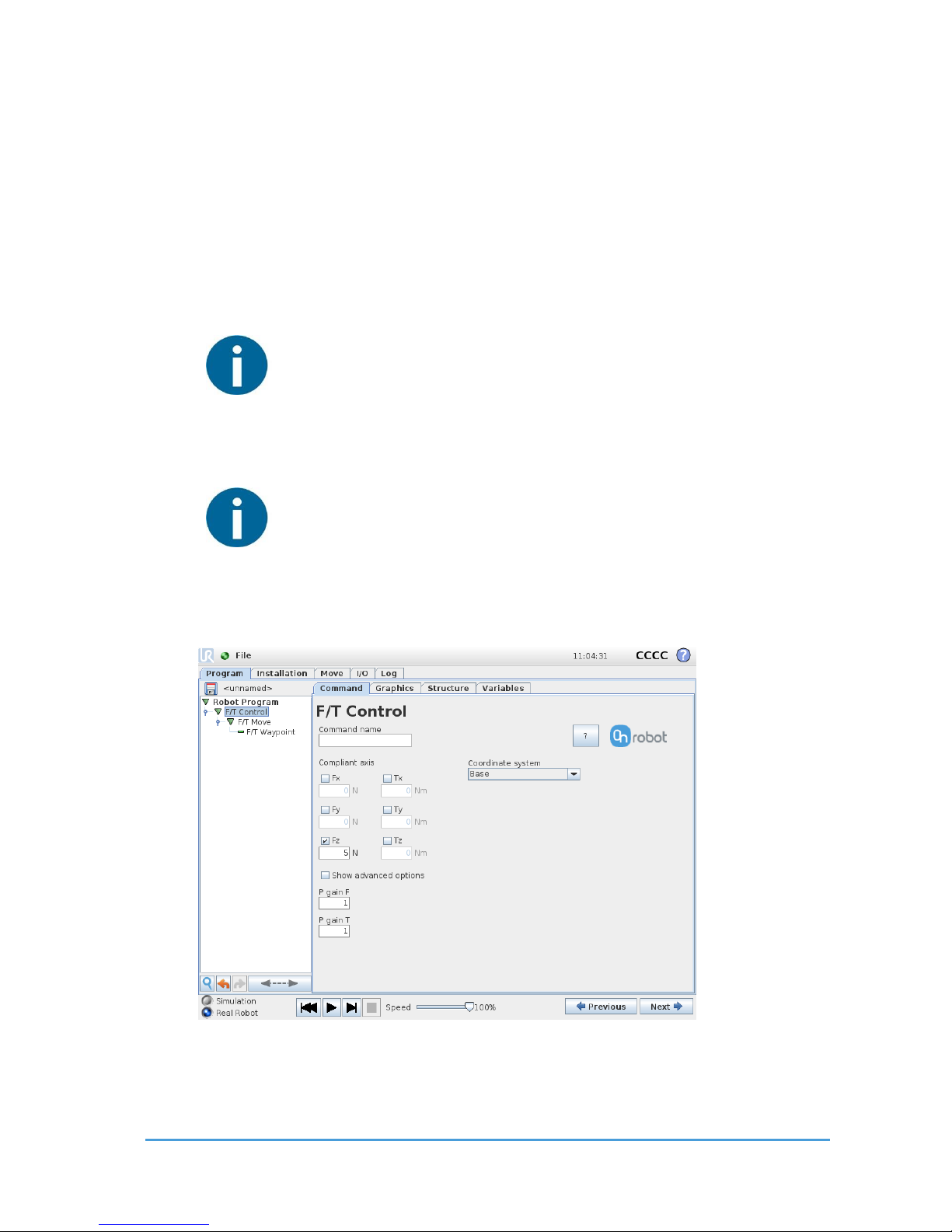
Compliant axis Fx, Fy, Fz, TX, TY, TZ: The axis selection that needs to be compliant. If an axis
is enabled (compliant) the movement along/about that axis is force/torque controlled
Page 45
Using the URCap Plugin 45
OnRobot © 2018 www.onrobot.com
otherwise (non-compliant) position controlled. The enabled axis is controlled to keep the set
force/torque value constant. At least one compliant axis must be selected.
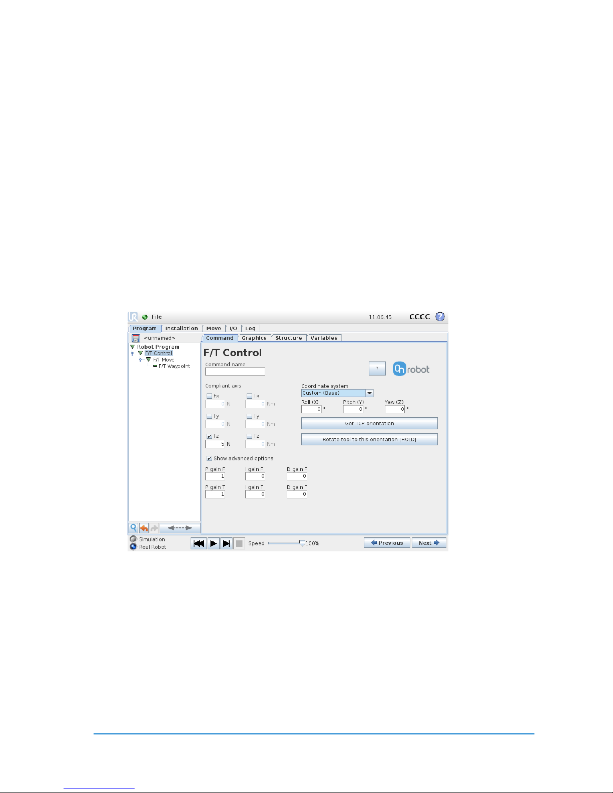
Coordinate system: The coordinate system used both for the movement and for the sensor
reading. It can be set to Base, Tool, Custom (Base) Custom (Tool) (according
to the UR’s reference frames). The Custom coordinate systems are calculated from the basis
coordinate system and the given Roll, Pitch and Yaw values. For the Custom (Base)
coordinate system, it is also possible to use the Get TCP orientation button to specify the
orientation of the coordinate system, by the orientation of the current TCP. To test the given
orientation, the Rotate tool to this orientation [HOLD] button can be used.
P Gain F: The force controller can be tuned with this proportional gain parameter. If any
overshoots or vibrations occur, try lowering the gain value (e.g.: 0.5).
P Gain T: The torque controller can be tuned with this proportional gain parameter. If any
overshoots or vibrations occur, try lowering the gain value (e.g.: 0.5).
Show advanced parameters checkbox: If checked then more options become available:
I Gain F: The force controller can be tuned with this integral gain parameter. If any
overshoots or vibrations occur, try lowering the gain value.
I Gain T: The torque controller can be tuned with this integral gain parameter. If any
overshoots or vibrations occur, try lowering the gain value.
D Gain F: The force controller can be tuned with this derivative gain parameter. If any
overshoots or vibrations occur, try lowering the gain value.
D Gain T: The torque controller can be tuned with this derivative gain parameter. If any
overshoots or vibrations occur, try lowering the gain value.
Page 46

Using the URCap Plugin 46
OnRobot © 2018 www.onrobot.com
This command has no return value.
Guidelines to PID force/torque controller settings:
The PID force/torque controller continuously calculates the error value for the
force/torque measured by the sensor, compared to the values set by the F/T
Control command, and applies correction based on this error.
P Gain: The proportional term produces a correction that is proportional to the current
error value. Increasing this parameter, has the following effects: faster reaction,
overreaction, lower error, stability degradation.
I Gain: The integral term produces a correction that is proportional to both, the
magnitude, and duration of the past error values. Increasing this parameter, has the
following effects: faster reaction, overreaction, lower error, stability degradation.
D Gain: The derivative term produces a correction that is proportional to the slope or
changing speed of past error values. Increasing this parameter, has the following
effects: less overreaction, stability increase.
If the force control is too slow, that is, the tool occasionally leaves the surface instead of
continually touching it, try increasing the P Gain, and I gain values.
If the force control is overreacting to changes, that is, the tool bounces off the surface,
try decreasing the P Gain (or D Gain, if it is above 1).
If the force control is reacting to changes too slowly, that is it keeps pushing the surface
hard after touching it, try decreasing the I Gain.
As a rule of thumb, it is recommended to use values:
1. P Gain < 5
2. I Gain < 0.25
3. D Gain < 1
4. The ratio of P Gain/I Gain = 10
Values that can be used as a base for tuning are:
P Gain F =1, I Gain F = 0.1, D Gain F = 0.3
P Gain T =0.2, I Gain T = 0, D Gain T = 0
Page 47

Using the URCap Plugin 47
OnRobot © 2018 www.onrobot.com
3.4 Script Function
When the OnRobot URCap is enabled, there will be a defined RG2-FT script function:
of_gripper_proxi_offsets(ProxL = 0, ProxR = 0)
This function can be used to cancel any offset of the optical (proximity) finger sensor. The
ProxL and ProxR are in millimeters.
3.4.1 Zero th e optical offset
To zero the optical finger sensor’s offset do the following steps:
1. Execute this script to unset any previous offset:
of_gripper_proxi_offsets(0,0)
2. Place a white sheet of paper between the fingers and fully close the gripper.
3. Write down the left (L) and right(R) distances showed at an F/T Measure node.
4. Execute this script to set the new offset with the wrote down values (L,R)
of_gripper_proxi_offsets(L,R)
5. Check again the displayed values at the F/T Measure node. The values now should
be very close to 0.
6. Make sure that the script is called in each program’s Before start section that
uses the optical finger sensor’s value (since the set offset will reset at power off)
of_gripper_proxi_offsets(L,R)
3.5 Software Uninstallation
To uninstall the URCap plugin, follow this process:
1. Go to the Welcome screen of the PolyScope.
2. Click Setup Robot.
3. Click on URCaps Setup and locate the RG - OnRobot in the list of active URCaps.
4. Click on the - sign at the bottom to uninstall it.
5. Restart the robot.
Page 48
List of Acronyms 48
OnRobot © 2018 www.onrobot.com
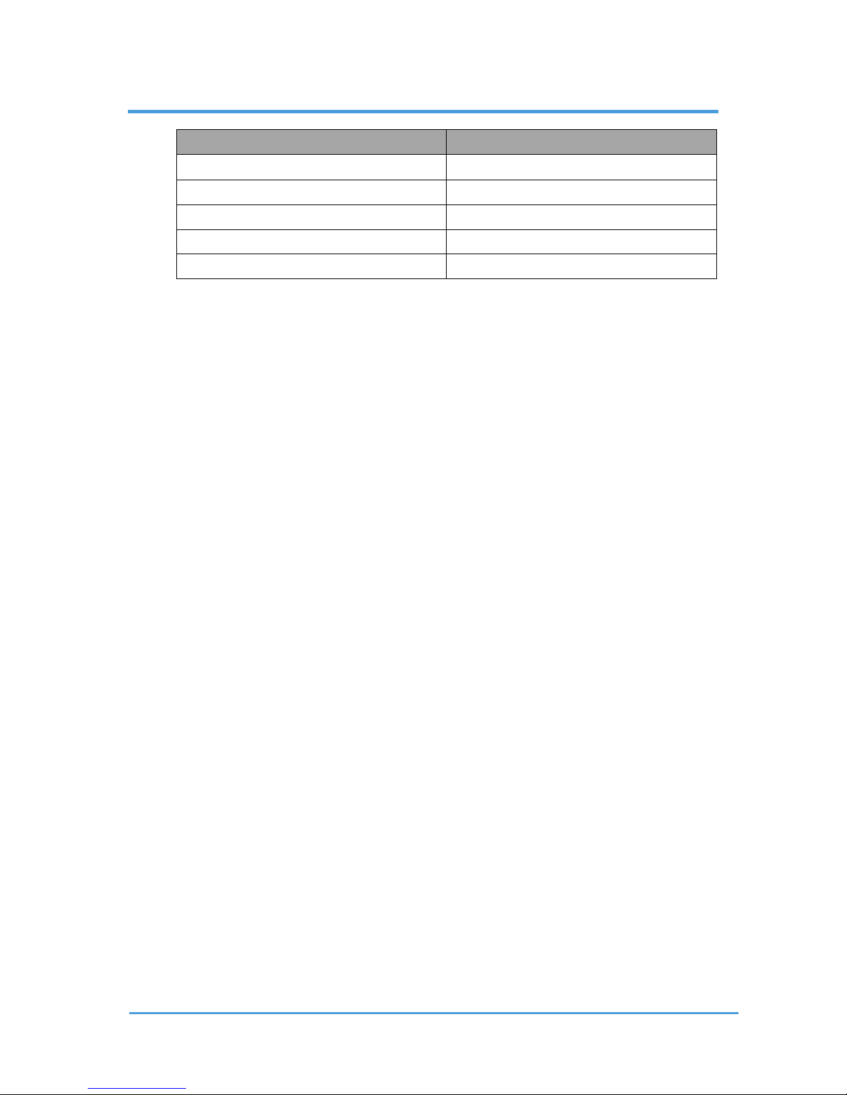
4 List of Acronyms
Acronym
Expansion
I/O
Input/Output
TCP
Tool Center Point
UR
Universal Robots
URCap
Universal Robots Capabilities
USB
Universal Serial Bus
Page 49
Appendix 49
OnRobot © 2018 www.onrobot.com
5 Appendix
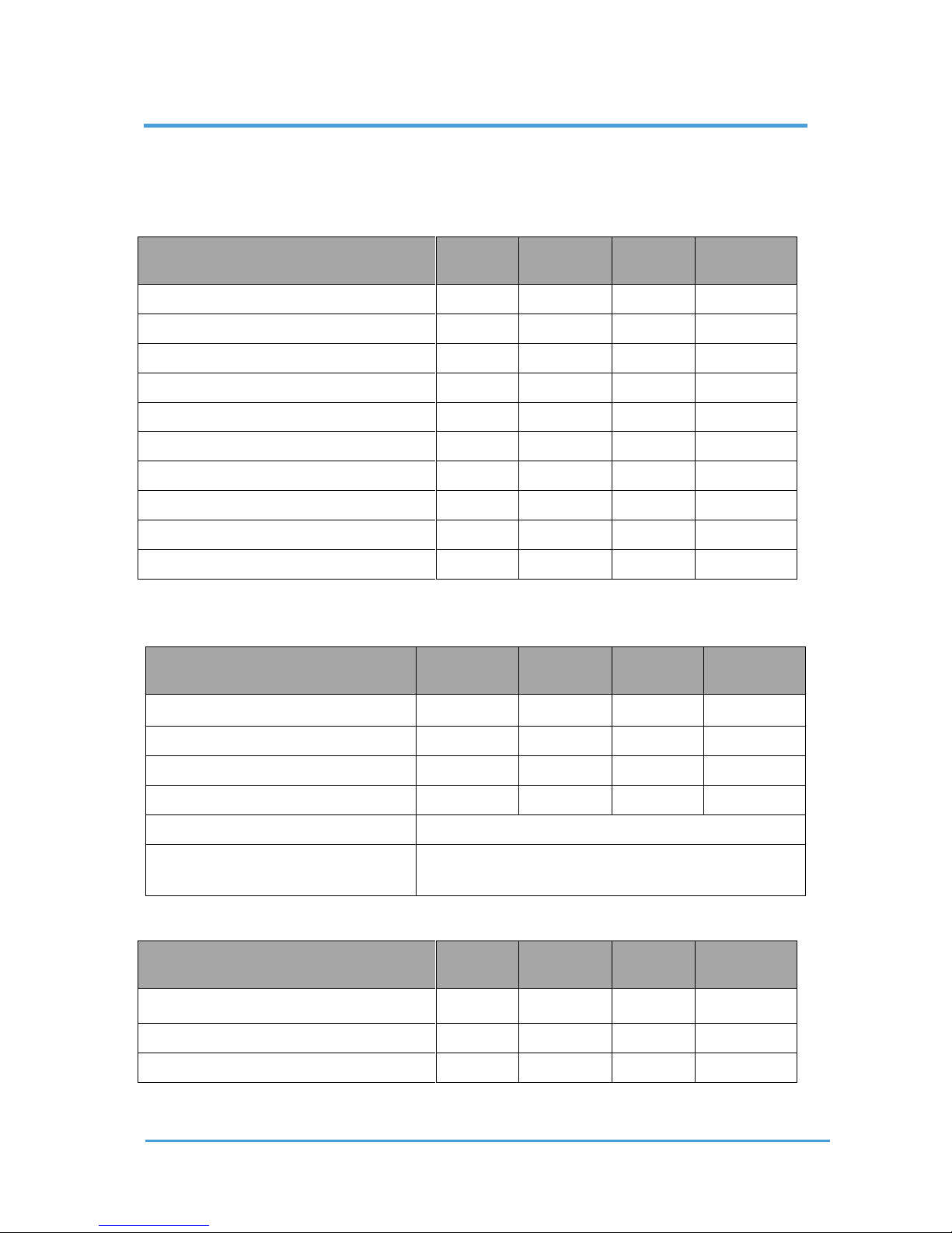
5.1 Technical Specifications
RG2-FT General Properties
Min
Typical
Max
Units
Total stroke (adjustable)
0 - 100
[mm]
Finger position resolution
-
0,1 - [mm]
Repetition accuracy
-
0,1
0,2
[mm]
Reversing backlash
0,2
0,4
0,6
[mm]
Gripping force (adjustable)
3 - 40
[N]
Gripping speed*
55
110
184
[mm/s]
Gripping time**
0,04
0,07
0,11
[s]
Ambient operating temperature
5 - 50
[°C]
Storage temperature
0 - 60
[°C]
Weight (without Compute Box)
-
0,77 - [kg]
* see speed table
** based on 8mm total movement between fingers, see speed table
Force Sensor Properties
Fxy
Fz
Txy
Tz
Nominal capacity (N.C.)
20 N
40 N
0.7 Nm
0.5 Nm
Single axis overload
200 %
200%
200%
200%
Noise free resolution
0.1 N
0.5 N
0.005 Nm
0.005Nm
Single axis deformation at N.C.
0.4 mm
0.1 mm
2°
5°
Temperature compensation
0 C° to +55°C
Full scale nonlinearity Temperature
compensation
< 2%
Part Sensor Properties
Min
Typical
Max
Units
Sensing range
0 - 100
[mm]
Resolution*
3 1 0.5
[mm]
Accuracy
-
± 25 - [%]
* the actual resolution depends on the object properties (e.g: surface type and color)
Page 50
Appendix 50
OnRobot © 2018 www.onrobot.com
Electrical Properties
Min
Typical
Max
Units
Power requirement
24 - 24
[Vdc]
Total power consumption (with CB)
6.5 - 22
[W]
5.2 Changing the IP of the Comput e Box
To change the IP address of the sensor, connect your laptop or an external PC to the
OnRobot Compute Box.
1. Make sure that the device is not powered. Connect the device and the computer
with the provided Ethernet cable.
2. If your device is in the factory default settings, proceed to step 3. Otherwise, make
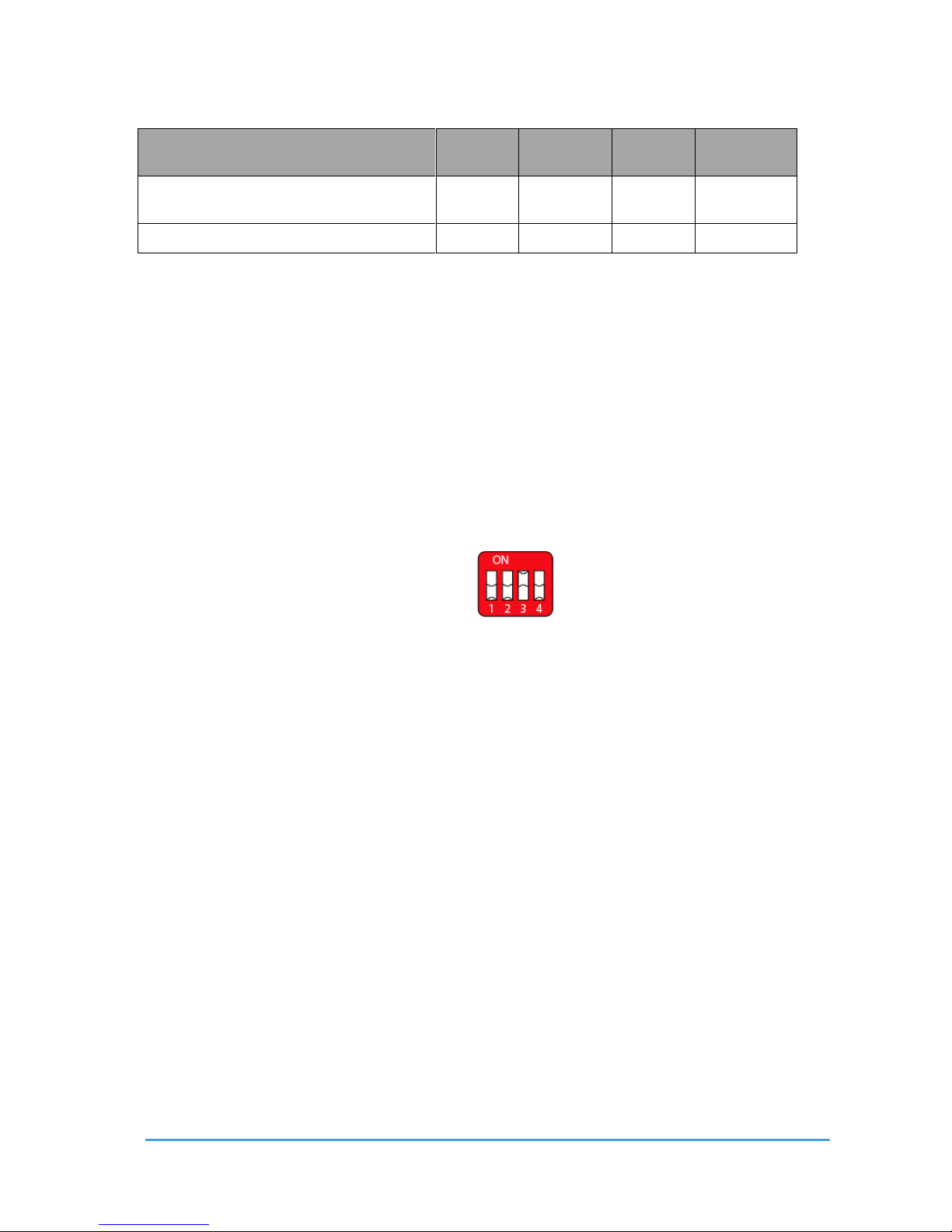
sure to switch the DIP switch 3 to the ON position (up) and the DIP switch 4 to the
OFF position (down).
3. Power the device from the provided power supply and wait 30 seconds for the
device to boot up.
4. Open a web browser (Firefox or Chrome is recommended) and navigate to
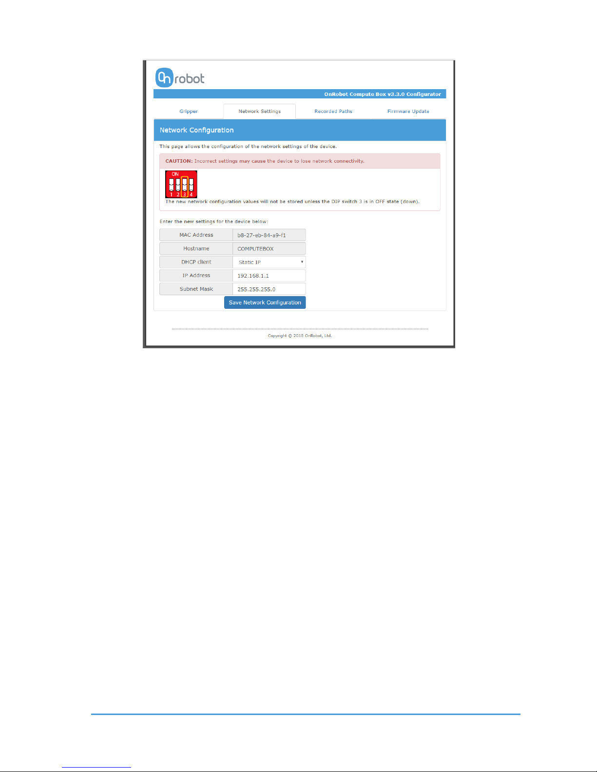
http://192.168.1.1. Then Click on Network Configuration in the top menu. The
following screen is displayed:
Page 51
Appendix 51
OnRobot © 2018 www.onrobot.com
5. Uncheck the Enable DHCP client checkbox, if it is checked.
6. Edit the IP Address.
7. Set DIP switch 3 to off position.
8. Click the Save Network Configuration button
9. Open a web browser (Firefox or Chrome is recommended) and navigate to the IP
Address set in step 7.
5.3 Return Values
Those OnRobot commands that has return values updates the of_return variable once
the command exit. This global variable can be used with the UR’s built in If conditional
expressions (for example: if of_return == 1 then do something).
5.3.1 F/T W i dth Com mand Ret urn Val u es
0 The Gripper Set Width command reached the set force or width.
5.3.2 F /T Mov e Command Return Values
0 The move ended without detecting a force or torque greater than the set limit.
1 The move ended, because a force or torque greater than the set limit was detected.
Page 52

Appendix 52
OnRobot © 2018 www.onrobot.com
3 The move cannot start due to a force or torque exceeding the set limit.
11 The move cannot start, because there is no recorded Path on the Compute Box with
the selected.
12 The move cannot start, because there are no recorded points in this Path.
13 The move cannot start, because the Path file found at this Path ID is empty.
14 The move cannot start, because the Path file is corrupted.
5.3.3 F/T S earch C ommand R eturn Values
0 The search ended successfully, because a force or torque greater than the set limit
was detected.
1 The search ended without detecting a force or torque greater than the set limit.
3 The search cannot start due to a force or torque exceeding the set limit.
11 The search cannot start, because there is no recorded Path on the Compute Box
with the selected.
12 The search cannot start, because there are no recorded points in this Path.
13 The search cannot start, because the Path file found at this Path ID is empty.
14 The search cannot start, because the Path file is corrupted.
5.3.4 F/T D e tect Command Re turn Val ues
0 Part detected.
1 Nothing detected.
5.3.5 F/T I n sert P a rt Comman d Retur n Values
0 The Insert Part command reached the maximal distance.
1 The Insert Part command exited at a bump after the minimal insertion depth.
2 The Insert Part command got stuck after the minimal insertion depth. Insertion is
slower than required.
3 The Insert Part command got stuck before the minimal insertion depth. Insertion is
slower than required.
4 The Insert Part command exited with timeout after the minimal insertion depth.
Page 53

Appendix 53
OnRobot © 2018 www.onrobot.com
5 The Insert Part command exited with timeout before the minimal insertion depth.
6 The Insert Part command exited due to too high side-forces/-torques at the non-
compliant axes after the minimal insertion depth.
7 The Insert Part command exited due to too high side-forces/-torques at the non-
compliant axes before the minimal insertion depth.
8 The Insert Part command has a parameter error.
Page 54
Appendix 54
OnRobot © 2018 www.onrobot.com
5.4 Troubleshooting
5.4.1 URCap P lugin Setup err or
There are three possible reason why the error icon could be displayed.
1. If the Discovered devices drop-down menu shows “NO DEVICES FOUND!” error
message for troubleshooting, see “No devices found”.
2. If the OnRobot device(s) found successfully but the UR Robot IP shows “N/A” for
troubleshooting, see UR Robot IP is “N/A”.
3. If both the OnRobot device(s) found successfully and the UR Robot IP shows a valid
IP address, then for troubleshooting see Device found, and UR has IP.
5.4.1.1 “No devices found”
If the Discovered devices drop-down menu shows “NO DEVICES FOUND!” error check the
connections with the Compute Box and the sensor, then try to restart the Compute Box.
After 60 seconds (when both status LEDs of the Compute Box turned to green) try to
manually repeat the discovery by tapping on the refresh icon.
5.4.1.2 UR Robot IP is “N/A”
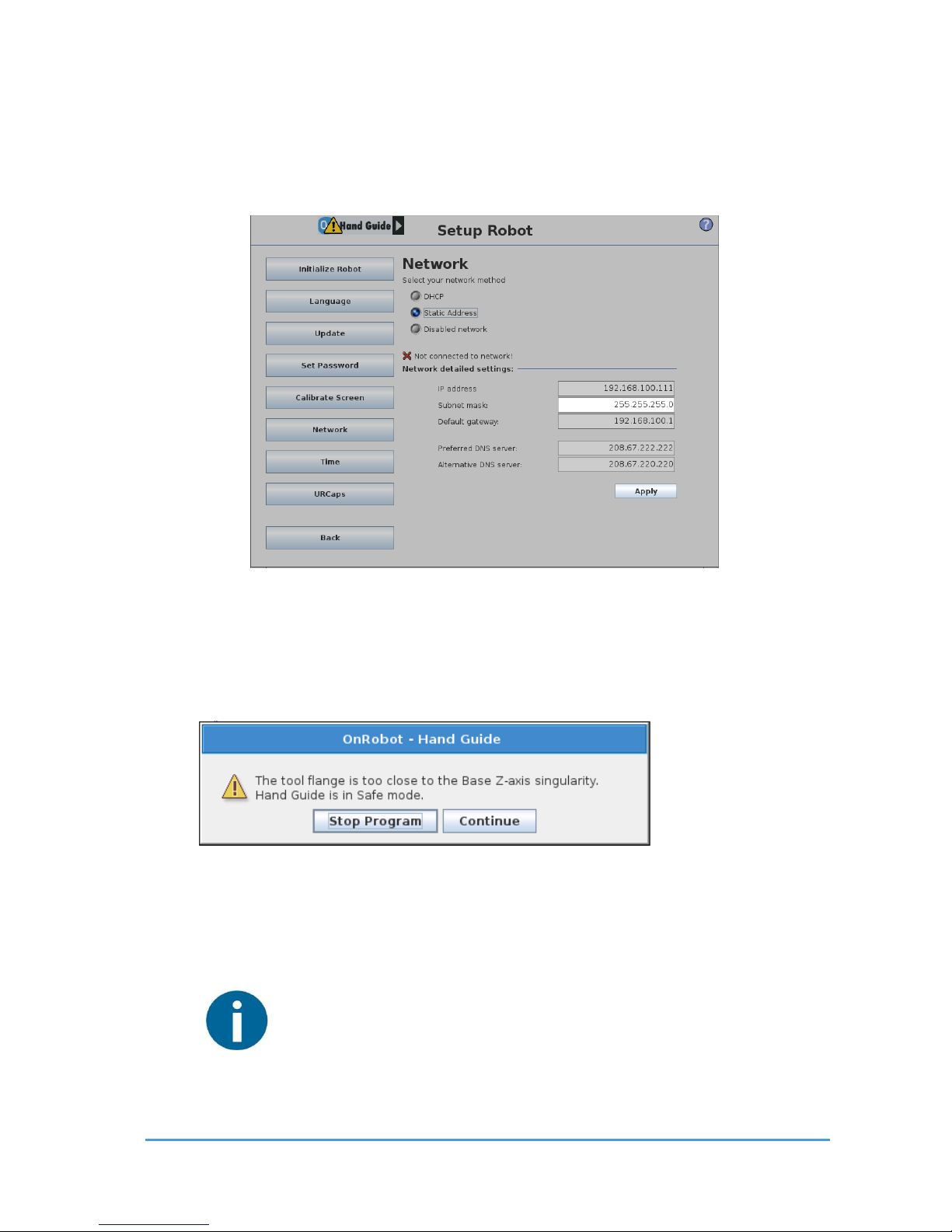
This error can happen, when the Network Configuration of the UR Robot has not been set.
To resolve the problem, check the Network Configuration of the UR Robot, by doing the
following:
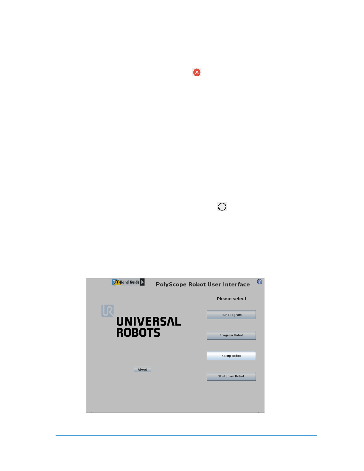
1. Press the Setup Robot button.
Page 55
Appendix 55
OnRobot © 2018 www.onrobot.com
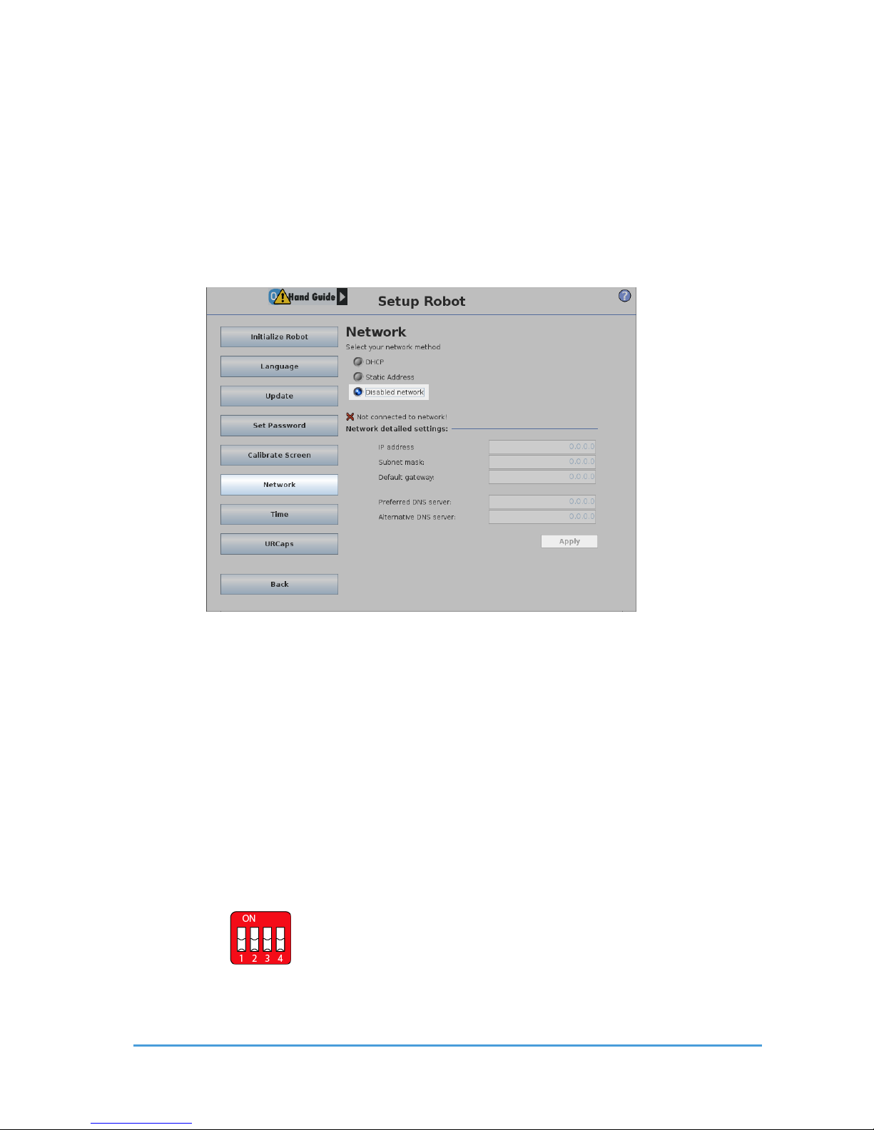
2. Press the Setup Network button.
3. If the network of the UR is disabled:
4. If the OnRobot device is connected to the UR robot directly, select DHCP, and press
the Apply button. The OnRobot service assigns an IP.
5. If the OnRobot device is not directly connected to the UR robot, check if the
OnRobot device is connected to the same network (router, switch, and so on) as the
UR Robot, or consult the Network Supervisor.
6. If DHCP or Static Address is selected, and the problem remains consult your Network
Supervisor.
In case of a DHCP, after the proper IP address is assigned to the UR robot switch to Static
address mode (the IP address of the UR robot should remain the same) and press the Apply
button. The IP address is now fixed and does not change later.
Finally start over with the URCap Plugin Setup.
5.4.1.3 Device found, and UR has IP
This error can happen when the robot and device are not in the same subnet.
To resolve the problem, follow this procedure:
1. If the OnRobot device is not directly connected to the UR Robot, check if the DIP
Switch 3 is in off state on the Compute Box, as shown on the following figure:
2. If the DIP Switch is in on state, set it to off, then restart the OnRobot device (by
disconnecting the power) and repeat the steps in Example Setup section.
Page 56
Appendix 56
OnRobot © 2018 www.onrobot.com
If the problem is still present, follow this procedure:
1. Open the Setup Network page of the UR robot explained in UR Robot IP is “N/A”.
2. Modify the Subnet mask to “255.0.0.0”.
3. Press the Apply button.
Finally start over with the URCap Plugin Setup.
5.4.2 T oo Close to Si ngularit y
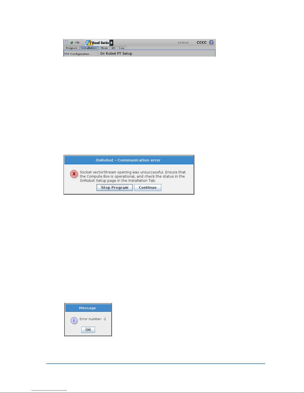
During hand guiding, if the tool is guided too close to the cylindrical volume directly above or
below the robot base, a warning message is displayed.
Pressing the Stop Program button will disable the Hand Guide function. Pressing the
Continue button will switch to Safe Mode, which prevents the tool flange from moving into
the cylindrical volume directly above or below the robot base by the Hand Guide function.
Moving 10 mm away from that volume turns Safe Mode off, enabling movement in all
directions again.
NOTE:
For safety and accuracy, the Hand Guide mode keeps the tool flange at a
greater distance from the cylindrical volume than the physical possibility of
the UR robot. Moving the tool flange closer is possible, by using the
PolyScope Move tab, or move commands.
Page 57
Appendix 57
OnRobot © 2018 www.onrobot.com
5.4.3 Warning sign on Hand Gu ide Bar
If the OnRobot device is not running properly, a warning sign appears. Repeat the steps of
the URCap Plugin Setup.
5.4.4 “socket_read_binary_in teger: timeout ”
If any command is running for more than 2 seconds, a socket_read_binary_integer: timeout
entry appears in the Log.
This has no impact on the program execution by the robot.
5.4.5 “Socket vectorStream op ening was unsuc c essful. ”
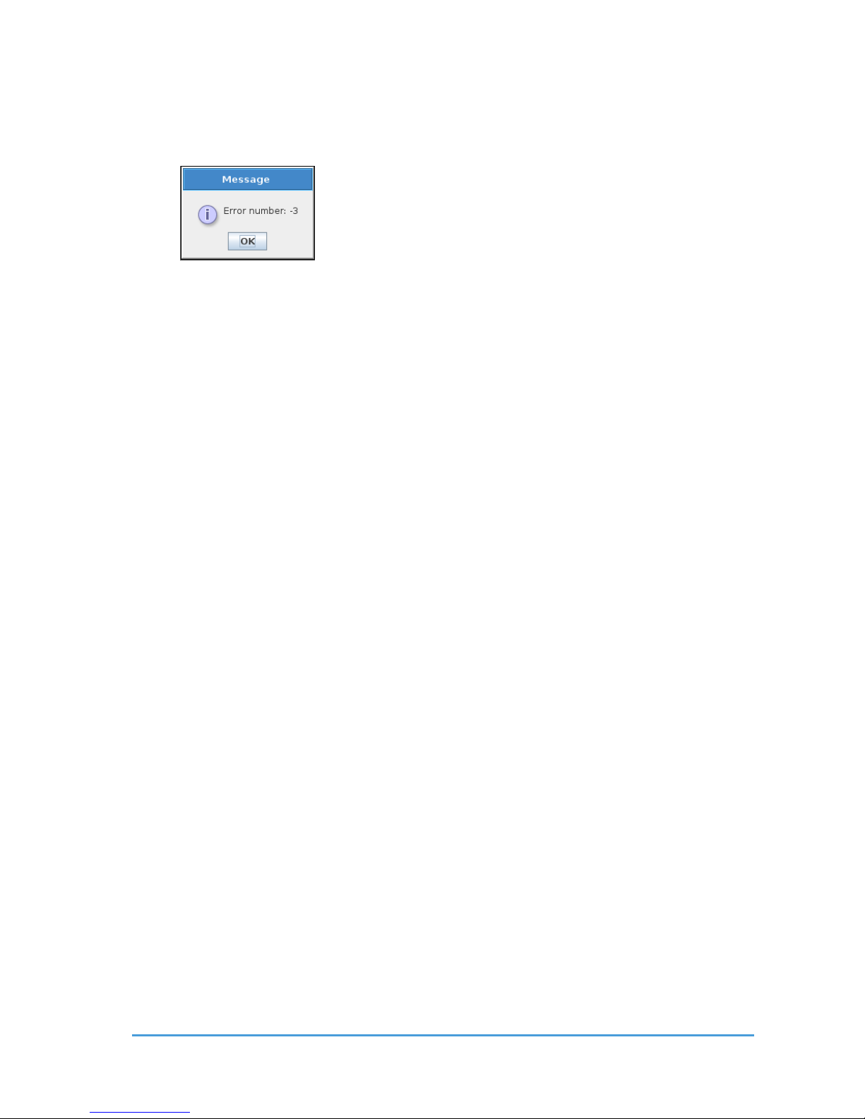
If the Robot Controller cannot connect to the Compute Box, the “Socket vectorStream
opening was unsuccessful.” error message is displayed.
In this case, ensure that the Compute Box is connected to the Robot Controller, and
powered on.
5.4.6 Path Re play is Slower t han Exp ected
When using the F/T Path command, it is possible that the recorded Path is not smooth
due to the limits of human dexterity. In these cases, the robot can only replay the Path at a
very slow speed. To avoid this problem, try recording the Path again, with confident smooth
movements with as little variations in translational and rotational speeds, as possible. Also,
try to avoid recording Paths that contain rotations without translational elements.
5.4.7 “Error number -2” on Path Saving
If an empty Path is recorded, when trying to save the path, the “Error number: -2” error
message is displayed.
In this case, ensure that the robot is moved between starting and stopping the path
recording function.
Page 58
Appendix 58
OnRobot © 2018 www.onrobot.com
5.4.8 “Error number -3 ” on Path Saving
If a Path cannot be saved due to not enough storage space on the Compute Box, the “Error
number -3” error message is displayed.
In this case, delete previously recorded paths that are not used anymore.
Page 59

Appendix 59
OnRobot © 2018 www.onrobot.com
5.5 Declarations and Certificates
5.5.1 CE/EU Declaration of Incorpor ation (original)
According to the European Machinery Directive 2006/42/EC annex II 1.B.
The manufacturer:
OnRobot A/S
Teglværskvej 47H
DK-5220, Odense SØ
Denmark
+45 53 53 57 37
declares that this product:
Type: Industrial Robot Gripper
Model: RG2-FT
Serial number from: 0108000001 (find actual number in the gripper’s back side)
is partly completed machinery according to 2006/42/EC. The product must not be put into
service before the complete machine is in full compliance with all essential requirements of
2006/42/EC. A comprehensive risk assessment must be carried out for each application as
part of ensuring that all essential requirements are fulfilled. All essential requirements must
be assessed. Instructions and guidance provided in the RG2-FT user manual must be
followed.
Technical documentation compiled according to 2006/42/EC annex VII part B is available to
national authorities upon request.
The product is in conformity with, and CE marked according to, the following directives:
2014/30/EU — Electromagnetic Compatibility Directive (EMC)
2011/65/EU — Restriction of the use of certain hazardous substances (RoHS)
2014/35/EU — Low Voltage Directive (LVD)
Nicolae Gheorghe Tuns
RD Director
Odense, August 1st, 2018
Page 60

Appendix 60
OnRobot © 2018 www.onrobot.com
5.6 Editions
Edition
Comment
Edition 1
This is the First Edition of this document.
 Loading...