

Page 1
Access Point
User’s Guide
012-0001-00
Page 2

FCC Compliance and Advisory Statement This hardware device complies with Part
15 of the FCC Rules. Operation is subject to the following two conditions: 1) this device
may not cause harmful interference, and 2) this device must accept any interference
received, including interference that may cause undesired operation. This equipment
has been tested and found to comply with the limits for a Class B digital device,
pursuant to Part 15 of the FCC Rules. These limits are designed to provide reasonable
protection against harmful interference in a residential installation. This equipment
generates, uses, and can radiate radio frequency energy and, if not installed or used in
accordance with the instructions, may cause harmful interference to radio
communications. However, there is no guarantee that interference will not occur in a
particular installation. If this equipment does cause harmful interference to radio or
television reception, which can be determined by turning the equipment off and on, the
user is encouraged to try to correct the interference by one or more of the following
measures: 1) reorient or relocate the receiving antenna; 2) increase the separation
between the equipment and the receiver; 3) connect the equipment to an outlet on a
circuit different from that to which the receiver is connected; 4) consult the dealer or an
experienced radio/TV technician for help. Any changes or modifications not expressly
approved by the party responsible for compliance could void the user's authority to
operate the equipment. Where shielded interface cables have been provided with the
product or specified additional components or accessories elsewhere defined to be
used with the installation of the product, they must be used in order to ensure
compliance with FCC regulations.
Canadian DOC Statement This digital device does not exceed the Class B limits for
radio noise emissions from digital apparatus specified in the interference-causing
equipment standard entitled "Digital Apparatus," ICES-003 of the Department of
Industry.
Page 3

Ultra-Link Processing™ - Access Point
Table of Contents
Product Overview ......................................................................................................................................... 3
Enclosure Features .................................................................................................................................... 3
Power-Over-Ethernet (PoE) ...................................................................................................................... 3
Lightning Protection .............................................................................................................................. 3
Environmental/Operational Parameters .................................................................................................. 4
Installation .................................................................................................................................................... 5
Professional Installation ............................................................................................................................ 5
Vertical Mounting ..................................................................................................................................... 5
Wall Mount ........................................................................................................................................... 5
Pole Mount ........................................................................................................................................... 6
Horizontal Mounting ................................................................................................................................. 6
Rack Mount ........................................................................................................................................... 6
Cabling........................................................................................................................................................... 8
Connections .............................................................................................................................................. 8
Antenna Parameters ................................................................................................................................. 9
Safety information ...................................................................................................................................... 11
Access Point User’s Guide 012-0001-00 P a g e | i
On-Ramp Wireless © 2010
Page 4

Ultra-Link Processing™ - Access Point
Access Point User’s Guide 012-0001-00 P a g e | ii
On-Ramp Wireless © 2010
Page 5

Ultra-Link Processing™ - Access Point
Product Overview
Each Access Point supports tens of thousands of sensors and can simultaneously demodulate signals
from up to 1000 sensors using a unique patented multiple access scheme. With 172 dB of total
allowable path loss (FCC/IC regulatory regions) the ULP network can easily be deployed using a star
topology configuration, overcoming the limitations of legacy wireless sensor networks (802.11, 802.15.4,
900 MHz FHSS) that require complicated mesh protocols to extend range or operate in a capacity limited
simplex mode.
Enclosure Features
On-Ramp Wireless’ Ultra-Link Processing™ Access Point is housed in a rugged weatherproof enclosure
that is ideal for both indoor and outdoor applications. Constructed of heavy gauge aluminum, it is
designed for high temperature and corrosive environments. The AP can be mounted in a vertical or a
horizontal orientation.
The lid interior features a channeled gasket that provides environmental protection. The lid is secured to
the housing with retained stainless steel heavy duty screws. For maintenance purposes, the lid can be
opened (150 degree opening angle) for easy part replacement, or completely removed to provide
additional servicing options.
Power-Over-Ethernet (PoE)
A CAT5 PoE interface is used to split the Data and Power carried by a CAT5 cable to the internal
equipment. The interface includes Lightning Protection and support for normal and reverse polarity POE
equipment. To supply the required current to the equipment, the HyperLink BT-CAT5-P1-4848 power
supply and injector kit should be used. Cisco® PoE equipment requires substitution of a BT-CAT5P1R4848 kit to supply 48 volt reverse polarity. An optional PoE interface surge protector can be added
to add protection for a second CAT5 cable.
Lightning Protection
The PoE interface features built in lightning protection. This helps add an extra level of protection to PoE
equipment installed in the enclosure. In addition, the unit can accept up to two optional bulkheadmount N-Type lightning protectors to protect the coaxial cable runs. An additional PoE interface can be
purchased for use in the enclosure.
Access Point User’s Guide 012-0001-00 P a g e | 3
On-Ramp Wireless © 2010
Page 6

Ultra-Link Processing™ - Access Point
Environmental/Operational Parameters
The Access Point was tested to ETSI EN 300 019-2-4 Specification T4.1 for non-weatherprotected locations.
Manufacturer’s Name: On-Ramp Wireless
Manufacturer’s Address: 10920 Via Frontera, Suite 200, San Diego, CA 92127, USA
Declares our sole responsibility that the product:
Product Name: On-Ramp Wireless Access Point, ULPAP110
Conforms to the following Product Specifications:
Safety: IEC 60950-1:2005 (2nd Edition); AM 1:2009
UL 60950-1:2003 R7.06
CAN/CSA-C22.2 No. 60950-1-03
EMC: FCC Part 15, Subpart B, Class B
R&TTE Directive 1999/5/EC
ETSI EN 301 489-3 V2.4.1 (2002-08)
EN55022: 2006/A1 2007 Class B
EN 61000-3-2: 2006
EN 61000-3-3: 2008
EN 61000-4-3: 2006
EN 61000-4-2: 2009
EN 61000-4-4: 2004
EN 61000-4-6: 2009
ICES–003:2004 Class B
ANSI C63.4-2003
The product herewith complies with the requirements of the Low Voltage Directive 2006/95/EC,
the EMC Directive 2004/108/EC and carries the CE marking. In addition, it complies with the
WEEE Directive 2002/96/EC and RoHS Directive 2002/95/EC.
The product was tested in a typical configuration.
Flame Rating approvals:
• File #E206630, Listed UL 50, UL 508
• CSA Approved
• Det Norske Veritas File #8281.1/FERe
• Maritime Register of Shipping #83033.250
RoHS Compliant Yes
Access Point User’s Guide 012-0001-00 P a g e | 4
On-Ramp Wireless © 2010
Page 7
Ultra-Link Processing™ - Access Point
Access Point Enclosure
Bottom View
GPS
Link
Status
Antenna
180
180
225
195
Installation
Professional Installation
The ULPAP110, and any associated equipment requires professional installation; a) installation of the
equipment must be controlled, b) Installation must be performed by licensed professionals, c)
installation of the equipment requires special training (special programming, field strength
measurements and transmit power calculations) to meet FCC/IC guidelines.
Vertical Mounting
Wall Mount
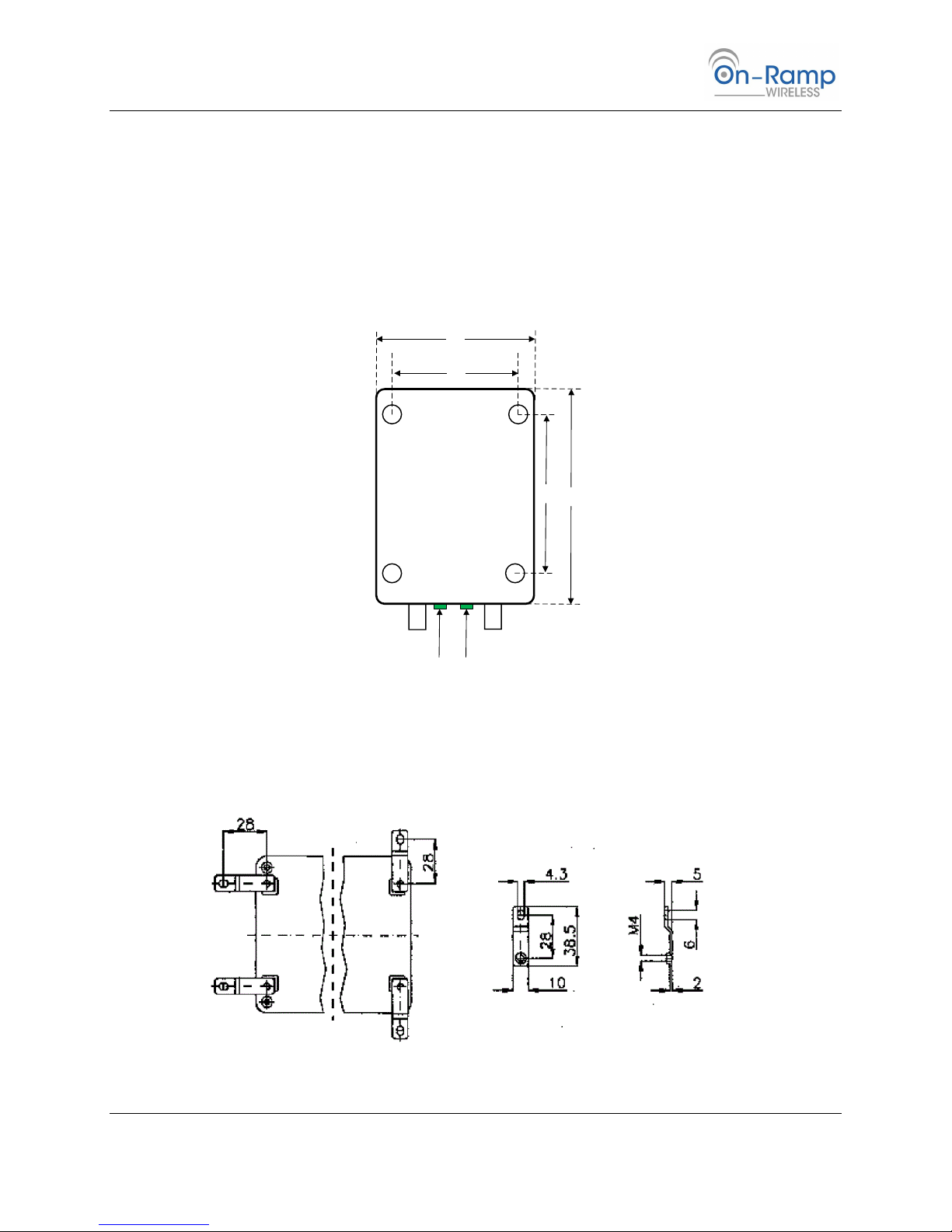
Figure 1: Mounting hole dimensions (cm)
Figure 2: Mounting tabs installed on the AP
Access Point User’s Guide 012-0001-00 P a g e | 5
On-Ramp Wireless © 2010
Page 8

Ultra-Link Processing™ - Access Point
Note: Mount the AP directly to non-metallic wall studs if possible; do not secure the AP to a drywall
surface. When stud spacing exceeds the AP’s mounting dimensions, secure ½” plywood to the
studs and secure the AP to the plywood mount.
1. Place the AP against the mounting location.
2. Drill a 3/16” hole through each of the mounting tabs and into the mounting surface.
3. Insert a ¼” x 1” wood screw thru each mounting tab and into the mounting surface.
4. Tighten each screw until it is secure against the mounting surface.
5. Ground the AP to an appropriate ground.
Pole Mount
1. Turn the AP upside down and orient it so that the antenna outputs face you (see Figure 3:
Mounting hole dimensions (cm)). The mounting hole dimensions will be visible.
2. Place the slotted struts over the mounting holes. Orient the struts horizontally.
3. Slide a flat washer onto the 5/16” hex head thread cutting screw.
4. Insert the screw and washer thru the slotted struts and into the AP housing’s mounting holes.
5. Using a 10mm nut driver, thread the screw into the mounting hole.
6. Tighten each screw until snug against the slotted strut.
Note: Avoid over-tightening the screws
7. When both slotted struts are secured to the AP enclosure, slide a 1 strut mount clamp (1” or 2”
depending on the application) onto each slotted strut.
8. Once the strut mount clamps mounted on the struts, slide the AP onto the pole. Make sure that
the antenna cables face downward.
9. Tighten the mounting clamp bolts so that the AP enclosure is secure against the pole.
Horizontal Mounting
Rack Mount
Orient the Access Point enclosure so that the antenna connectors and indicator lights are facing you.
1. Loosen the 4 top cover securing screws using a flat-blade 5/16” X 6” screwdriver.
Note The top cover screws are retained
2. Lift the cover strait up and open it by lifting the right hand side.
3. Remove the two keeper screws located next to the hinge posts.
4. Lift the cover off of the enclosure and set aside.
a. Insert the keeper screws into their mounting holes and partially screw them down to avoid
loss.
5. Using a ¼” x 4” flat blade screwdriver, loosen the mounting tabs.
6. Rotate the mounting tabs 90 degrees from their horizontal orientation to a vertical orientation.
Access Point User’s Guide 012-0001-00 P a g e | 6
On-Ramp Wireless © 2010
Page 9

Ultra-Link Processing™ - Access Point
a. It may be necessary to offset the vertical orientation a few degrees from 0 vertical in
order to align the mounting tabs with available thru holes in the rack tray.
7. Slide rack tray half way out of the rack.
8. Place the AP on the rack tray and align the mounting tabs so that they offer a clear mounting
point.
9. Orient the unit so that the antenna connectors are facing you.
10. Place a ¼” x ½” screw into each mounting tab.
11. Secure a fixing nut, from the bottom of the rack tray, onto each screw and tighten the nut.
12. Slide the rack tray into the rack when the AP is secured to the rack tray.
Access Point User’s Guide 012-0001-00 P a g e | 7
On-Ramp Wireless © 2010
Page 10
Ultra-Link Processing™ - Access Point
Access Point Enclosure
Top View
GPS
Link
Status
Antenna
Cabling
Connections
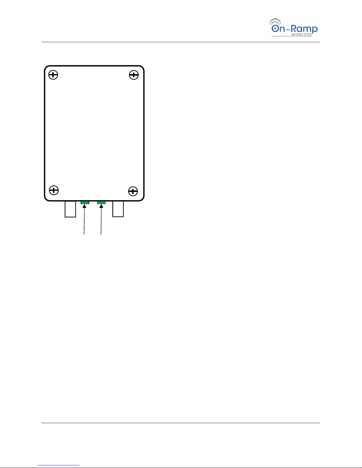
Connect GPS antenna cable to the GPS connector (Male)
Connect the Antenna cable to the antenna connector (Male)
Connect the Power (PoE) to the Access Point
Access Point User’s Guide 012-0001-00 P a g e | 8
On-Ramp Wireless © 2010
Page 11
Ultra-Link Processing™ - Access Point
Manufacturer
Part Number
Gain
Type
L-com
HG2409UDT-PRO
9
Omni- -Tilt
Antenna Parameters
The FCC sets maximums transmit power limits. The AP’s maximum TX power capability is 30dBm.
Maximum allowable Effective Isotropic Radiated Power (EIRP) for the professionally installed Access
Point 36 dBm (4 watt).
The Access Point transmit output power is adjusted, if required as part of a professional installation,
using On-Ramp Wireless’ Network Management Software.
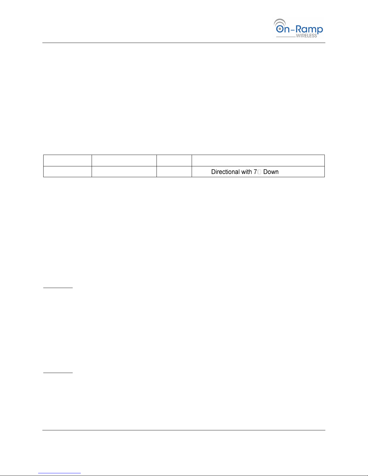
This device has been tested with the antennas listed below, and having a maximum gain of 9 dBi.
Antennas not included in this list or having a gain greater than 9 dBi are strictly prohibited for use with
this device. The required antenna impedance is 50 ohms.
Table 1 Typical Antennas, FCC configuration
Additional equivalent antennas from other manufactures may be substituted and then marketed with
this equipment. Equivalent antennas must be of the same type (e.g. Omni-Directional) and must be of
equal or less gain (9 dBi) than an antenna previously authorized under the same FCC ID, and must have
similar in band and out of band characteristics.
The output power at the antenna input must be measured and adjusted according to FCC guidelines.
This measurement accounts for AP transmit power and any losses in cables and connectors prior to the
input. The transmit power at the antenna input plus the antenna gain must not exceed 36 dBm (4W).
When using the 9dBi antenna the measured power at the antenna input must be 27 dBm or lower to
meet this requirement. When the antenna gain exceeds 6dBi the measured transmit power at the
antenna input must be measured and the transmit power at the Access Point must be set appropriately.
Example 1:
1. The antenna gain is 9 dBi
2. Output power at antenna input measured at 29 dBm (30 dBm AP transmit power - 1 dB of cable
loss)
3. EIRP = 29 dBm + 9 dBi = 38 dBm > 36 dBm requirement
4. What should the AP maximum power be set to so the installation is within the FCC maximum EIRP?
5. 38 dBm – 36 dBm = 2 dBm. Max power at AP should be 30 dBm – 2dBm = 28 dBm
When the antenna gain is less than or equal to 6 dBi the AP output power can be set at the full 30 dBm.
Example 2:
1. The antenna gain is 4 dBi
2. Output power at antenna input is 29 dBm (30 dBm AP transmit power – 1 dB of cable loss)
3. EIRP = 29dBm + 4 dBi = 33 dBm < 36 dBm
Access Point User’s Guide 012-0001-00 P a g e | 9
On-Ramp Wireless © 2010
Page 12

Ultra-Link Processing™ - Access Point
To reduce potential radio interference to other users, the antenna type and its gain should be so chosen
that the equivalent isotropically radiated power (E.i.R.P.) is not more than that permitted for successful
communication.
The responsibility for staying within these power limits falls on the professional installer.
Access Point User’s Guide 012-0001-00 P a g e | 10
On-Ramp Wireless © 2010
Page 13

Ultra-Link Processing™ - Access Point
Safety information
Always follow all warnings and instructions marked on the product.
Use only the power source indicated on the product regulatory label.
When storing or transporting this product, do not tilt or stand it on its side.
Avoid placing this product in an environment that is subject to rapid changes in temperature or humidity, mechanical shocks,
vibration, or dust.
Do not use aerosol products inside or around this product.
Do not attempt to repair or service this product.
Regulatory compliance
FCC statement The United states Federal Communications Commission (in CFR 47 Part 15.105) has specified that the following
notice be brought to the attention of the users of this product:
Note: This equipment has been tested and found to comply with the limits for a Class B digital device, pursuant to part 15 of the
FCC Rules. These limits are designed to provide reasonable protection against harmful interference in a residential installation. This
equipment generates, uses, and can radiate radio frequency energy and, if not installed and used in accordance with the
instructions, may cause harmful interference to radio communications. However, there is no guarantee that interference will not
occur in a particular installation.
CAUTION:
Pursuant to Part 15.21 of the FCC Rules, any changes or modifications to this product not expressly approved by OnRamp Wireless might cause harmful interference and void the FCC authorization to operate this product.
The radiated energy from this product is well below the FCC radio frequency exposure limits. Nevertheless, the product
shall be used in such a manner that the potential for human contact during normal operation is minimized.
This product and any attached external antenna, if supported, shall be placed in such a manner to minimize the potential
for human contact during normal operation. In order to avoid the possibility of exceeding the FCC exposure limits, human
proximity shall not be less than 25 cm (8 inches) during normal operation.
Canadian statements
This product meets the applicable Industry Canada technical specifications.
Operation is subject to the following two conditions: (1) this device may not cause interference, and (2) this device must accept any
interference, including interference that may cause undesired operation of the device.
This Class B digital apparatus complies with Canadian ICES-003.
Access Point User’s Guide 012-0001-00 P a g e | 11
On-Ramp Wireless © 2010
 Loading...