

Ono Sokki FP-4135 Instruction Manual

ON-BOARD VOLUMETRIC FLOW DETECTOR
FP-4135
Instruction Manual
ONO SOKKI CO., LTD.

■WARRANTY■
・ This document may not be reproduced, in whole or part, in any form or by any means without the prior written
permission of the publisher.
・ The contents of this document are subject to change without notice.
・ This document has been produced based on a series of strict verifications and inspections. Should a failure occur
nonetheless, please inform our sales representative or sales office.
・ Ono Sokki shall have no liability for any effect resulting from any operation, whether or not the effect is attributable
to a defect in the documentation.
Copyright © ONO SOKKI CO., LTD. 2017 All rights reserved.
WORLDWIDEONOSOKKICO.,LTD.
1-16-1Hakusan,Midori-ku,Yokohama226-8507,Japan
Phone:+81-45-935-3918/Fax:+81-45-930-1808(Overseassalesdepartment)
E-mail:overseas@onosokki.co.jp
1. Thisproductiscoveredbyawarrantyforaperiodofoneyearfromthedateofpurchase.
2. Thiswarrantycoversfree-of-chargerepairfordefectsjudgedtobetheresponsibilityofthemanufacturer,
i.e.,defectsoccurredwhiletheproductisusedundernormaloperatingconditionsaccordingtodescriptionsinthismanualandnoticesontheunitlabel.
3. Forfree-of-chargerepair,contacteitheryoursalesrepresentativeoroursalesofficenearby.
4. Thefollowingfailureswillbehandledonafeebasisevenduringthewarrantyperiod.
(a) Failuresoccurringthroughmisuse,mis-operation,ormodification
(b)Failuresoccurringthroughmishandling(dropping)ortransportation
(c) Failuresoccurringthroughnaturalcalamities(fires,eart
hquakes,flooding,andlightening),environmentaldisrup-
tion,orabnormalvoltage.
* Forrepairsafterthewarrantyperiodexpired,contactyoursalesrepresentativeoroursalesofficenearby.
* Outerappearanceandspecificationsaresubjecttochangewithoutpriornotice.
https://www.onosokki.co.jp/English/english.htm

1
FP-4135 On-Board Volumetric Flow Detector
Introduction
This manual describes the installation, mounting, piping, specications and precautions during the use of the FP-4135
On-Board Volumetric Flow Detector.
If you are using the FP-4135 On-Board Volumetric Flow Detector for the rst time, read this manual before you start
installing, piping or measuring.
Especially, some items described under “Precautions” in this manual might cause property damage. Be sure to follow
the instructions in this manual.
Also, if you are using the FP-4135 On-Board Volumetric Flow Detector in combination with the Ono Sokki DF-2200
On-Board Flow Meter or the FM Series Digital Flowmeter/Data Recorder, then you should read the manuals for each of
those equipment also.
Keep this manual in a safe place even after you nish reading because this document also serves as a warranty.
• The FP-4135 On-Board Volumetric Flow Detector went through stringent inspections before delivery and it has been veried
that it operates normally.
After unpacking the product, please check for damage during transfer. Next, check the basic operations by referring to this
manual.
• If any of the items are damaged or does not operate as described in this manual, immediately contact the nearest Ono Sokki
sales ofce or the distributor where you purchased the product.
z How to use this manual
Throughout this manual, the following symbols are used in addition to the safety and caution symbols. Before reading this
document, be sure to check the meanings of these symbols.
!
CAUTION
Indicates information about supplementary explanation or restrictions. We recommend reading the information
followed by this symbol.
!
IMPORTANT
Indicates important safety instructions that need to be observed. Be sure to read the instructions followed by this
symbol.
!
IMPORTANT
• The contents of this manual are subject to change without notice.
• No part of the contents of this document may be reprinted or reproduced without authorization.
• While the contents of this document have been prepared in our best efforts for perfection, should there be any unclear
point, error, or any other questionable point, please advise us of them.
• Please be advised that we should not be responsible for results of your operation, regardless of the preceding
paragraph.
• All corporate names and product names used herein are either trade names or registered trade names of their respective
holders.
!
CAUTION
2
For Your Safety
• Please read this manual before using the FP-4135 On-Board Volumetric Flow Detector.
• The FP-4135 On-Board Volumetric Flow Detector must be used by following the described contents in this manual.
• Precautions might be also described on the FP-4135 On-Board Volumetric Flow Detector unit itself or detailed in
other attached user manuals. Use while following the contents of those manuals too.
• Keep this manual in a safe place where it is readily available for future reference.
• Note that this manual merely covers the information at the time of publication. The contact information (e.g.,
company address, phone number, website URL, and e-main address) may be changed without prior notice. Thank
you for your understanding.
z Meaning of notations
In this manual, matters regarding the safe usage of the product is detailed in the following.
Each signal word indicates the degree of hazard caused by negligence of the suggested instructions or precautions.
Indicates a hazardous situation that, if not avoided, will result in death or serious injury.
Indicates a hazardous situation that, if not avoided, may result in minor injury or property damage.
Indicates hazardous situation, if not avoided, may result in property damage including failure of the
equipment, system, or facility, though not result in personal injury.
z Meanings of symbols
Information on operational hazard are given by using the 3 different symbols shown below. The following meanings are
dened for each symbol:
Symbol Denition Meaning Example
Attention Indicates failure to observe the instructions may cause a hazardous
situation.
The drawing in the symbol indicates the type of hazard involved.
Prohibition Indicates the actions you must avoid.
The drawing in the symbol illustrates the actions you must avoid.
Mandatory Indicates the things you have to do.
The drawing in the symbol illustrates the thing you have to do. To avoid
hazards, it is necessary to perform the instruction given in this symbol.
WARNING
CAUTION
NOTICE
3
FP-4135 On-Board Volumetric Flow Detector
Warning regarding use
WARNING
Always conduct measurements under the hazardous materials ofcers’ supervision.
• This equipment measures highly hazardous materials such as gasoline and light oil. Always conduct
measurements under the hazardous materials ofcers’ supervision.
Be careful of sources of re.
• As this equipment measures highly hazardous materials such as gasoline and light oil, be careful of sources of
re. Always conduct measurements under the hazardous materials ofcers’ supervision.
Make sure that detector is not contained in a closed space.
• If the detector is lled with liquid and is in a sealed condition with the outlet/inlet valve closed, the internal
pressure might rise due to a rise in temperature, causing a re from the leaked liquid.
• Make sure the liquid does not create a sealed condition by taking measures such as making an air layer inside
the piping.
Never let the liquid inside the detector evaporate.
• The evaporated liquid is highly inammable and may cause an explosion or re. Never let the liquid inside the
detector evaporate.
• The FP-4135 is designed to use the liquid to be measured as a lubricant for each operating part and if this
liquid evaporates (gasies), there will be not enough lubrication resulting in incorrect measurements.
Use this equipment within the operating temperature range designated in the specications.
• The environment/liquid operating temperature range for the ow detector part of the FP-4135 is -30 to +100°C
(non-freezing) and -30 to +70°C for the signal processing unit.
• Avoid measurement in abnormally high temperature as it might cause a re or explosion.
Do not pour any other liquid other than those given in the specications.
• The FP-4135 can measure the following liquids only. If you pour any other liquid other than those specied, it
might cause corrosion or damage to the detector’s internal parts and may cause injury to personnel.
For details, contact the nearest Ono Sokki sales ofce or the distributor where you purchased the product.
Gasoline, light oil, kerosene, petroleum-based general hydraulic oil, class-A heavy oil, engine oil, methanol,
ethanol, mixture of alcohol and gasoline and brake oil.
• This equipment might not be usable when in a depositing condition.
Avoid applying any vibration or impact.
• FP-4135 is a high precision equipment. Do not use or store it where any vibrations exist.
• Do not drop or handle it in a way which causes a strong impact on the equipment. Otherwise, it will cause
failure or malfunction of the equipment which may lead to injury.
Warning regarding installation
WARNING
Warning about line lter
• Do not use any other line lters than the one built into the detector. It might cause liquid leak which may cause
re or explosion.
• The built-in lter in the detector is designed to remove large debris in the piping connection, so use other line
lters upstream of the liquid inlet of the detector.
To mount the detector, use the mounting screws of the detector or screws included in the product only.
• The detector may tilt, or the equipment may fail or malfunction due to vibration, which may lead to personal
injury. To mount the detector, use the mounting screws on the detector or xtures included in the product only.
• If you have to use any other screws, contact the nearest Ono Sokki sales ofce or the distributor where you
purchased the product.
4
The engine right after it is stopped is at a very high temperature. Before installing or removing the
detector, make sure that the engine is cooled o.
• Otherwise, it might cause burns.
Warning about piping
WARNING
Make sure the power is disconnected (OFF) before starting piping.
• Make sure the power of the Ono Sokki DF-2200 On-Board Flow Meter or the FM Series Digital Flowmeter are
turned OFF.
• To switch the power on/off, use the power switch on the Ono Sokki DF-2200 On-Board Flow Meter or the FM
Series Digital Flowmeter after connecting the FP-4135 to the Ono Sokki DF-2200 On-Board Flow Meter or the
FM Series Digital Flowmeter with the ow signal cable.
Flush the detector before piping.
• The FP-4135 is delivered lled with oil to make sure internal parts are fully lubricated. Start measurement after
ushing thoroughly by pouring measurement liquid to within the specied ow rate of the detector.
Do not use air for ushing.
• If ushed with plant air or other air, it might cause over speeding of the detector leading to a failure. Do not
ush with any other liquid other than the ones specied.
When ushing, do not exceed the ow rate beyond the measurement range.
• Including during measurement, if you pour more liquid than the measurement range, it might cause a failure.
• Special care should be taken when excess air exists in the piping such as when you pour liquid into the piping
for the rst time as an excess ow rate can occur. Increase the ow rate gradually from zero.
Be careful not to cut yourself on the screws or couplings in the detector’s inlet/outlet.
• Wear a pair of gloves to prevent cutting your ngers or hands when you mount the couplings to change the
joints.
When measurement liquid leaks from the piping, it might cause a re or explosion.
• Remember to check the couplings or pipings for any leaks or looseness before pouring liquid.
Precautions on installation
WARNING
Handle the equipment as a precision equipment.
• FP-4135 is a high precision equipment. Install it in a place within the operating temperature range (-30 to
+100°C) with no large temperature uctuations or vibrations.
Install it at a lower position than the liquid tank.
• To gain supply pressure to the detector by height difference, install the detector at a lower position than the
liquid tank to prevent the formation of air pockets and negative pressure.
5
FP-4135 On-Board Volumetric Flow Detector
Precautions on piping
CAUTION
Do not confuse the IN and OUT parts of the detector.
• The detector has an inlet (IN) and an outlet (OUT) for the liquid. Recheck the inlet and the outlet when piping.
Recommendations on bypass valve installation
• Installing a bypass valve in piping is recommended to maintain the measured system such as an engine,
release air pockets out of the piping, or to repair detector malfunctions.
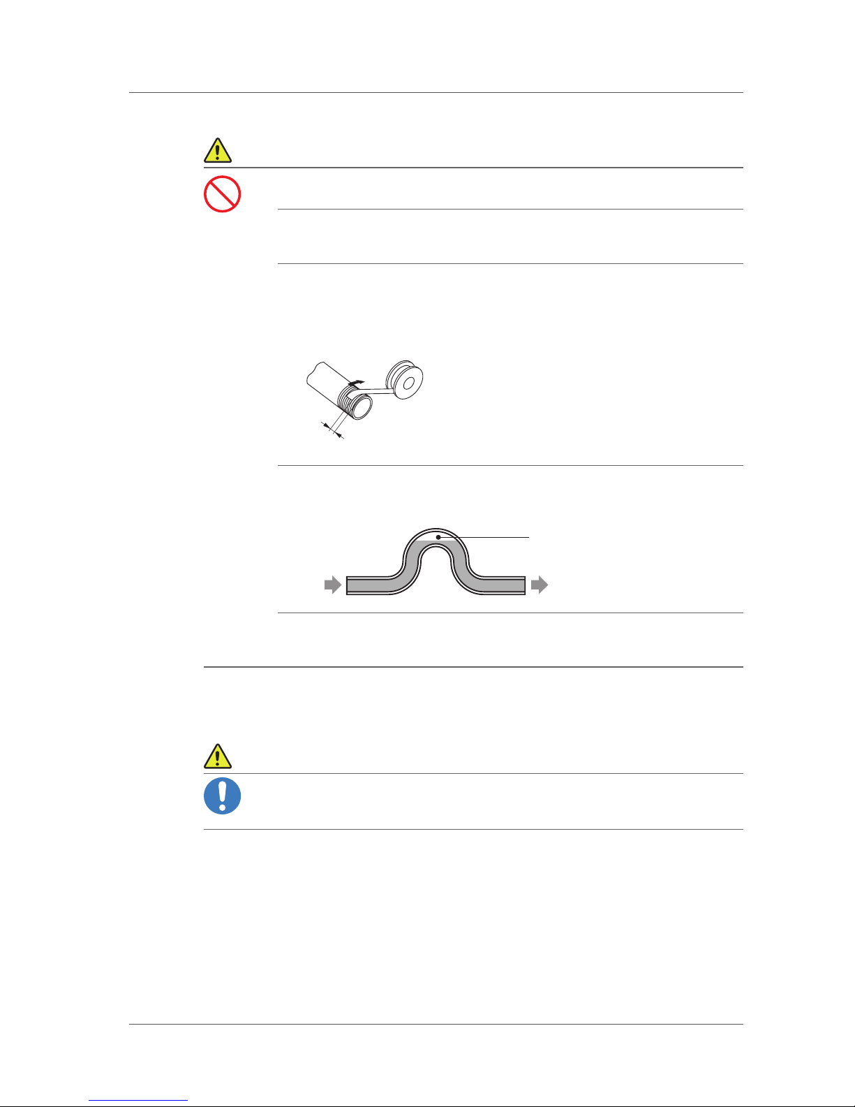
Pay attention to how to wind the seal material.
Follow the instructions below to wind a Teon seal tape on the screws to change the couplings.
• The seal tape should be wound around 2 to 2.5 times on a screw with the last 1 to 2 threads of a screw not
tightened.
• When using a liquid seal material, be careful not to leak the liquid material into the piping.
Leave space for about 2 threads.
Winding
direction
Seal tape
Do not bend piping into the shape of an arch.
• If pipings are bent into an arc shape, air pockets can be form in the top part and become hard to remove.
• If the piping has any air pockets, measurement will be incorrect. Take care.
Air pocket
Piping Piping
Fix the piping in front and to the rear of the detector.
• Use the appropriate xtures on the piping in front and to the rear of the detector to prevent leakage and
damage to the connection part of the detector by vibrations.
■■Precautions on Electromagnetic Environment
CAUTION
• This product is intended the equipment to be used in industrial electromagnetic environment.
• Using this product in a household may cause electromagnetic interference. In such a case, us
-
ers may be required to take appropriate actions.

6
Table of contents
Introduction ................................................................................................. 1
For Your Safety ............................................................................................2
1. Overview (Structure and Operating Principle) ............................................7
1.1 Product overview ...................................................................................................................................7
1.2 Structure and operating principle .....................................................................................................7
2. System Conguration.............................................................................8
3. Installation Method ................................................................................ 9
3.1 Name of components ...........................................................................................................................9
3.2 Precautions on installation.............................................................................................................. 10
3.3 Installation ............................................................................................................................................ 11
4. Piping Method ..................................................................................... 13
5. Measuring Method ............................................................................... 15
5.1 Basic measurement procedure ...................................................................................................... 15
5.2 Assembling the measurement system ....................................................................................... 16
5.3 Conguring the FACTOR ..................................................................................................................16
5.4 Conguring Flow Pulse ..................................................................................................................... 17
5.5 Checking piping ................................................................................................................................... 17
5.6 Pouring liquid ........................................................................................................................................ 17
5.7 Air bleeding ........................................................................................................................................... 18
6. Maintenance and Storage ..................................................................... 20
6.1 Daily check ........................................................................................................................................... 20
6.2 Periodic inspection and calibration ...............................................................................................20
6.3 Checking lter and cleaning ............................................................................................................20
6.4 Storage of On-Board Volumetric Flow Detector .......................................................................22
7. Appendix ........................................................................................... 23
7.1 Troubleshooting .................................................................................................................................. 23
7.2 Specications ...................................................................................................................................... 24
7.3 Outline dimensional drawing ........................................................................................................... 26
7
Overview (Structure and Operating Principle)
FP-4135 On-Board Volumetric Flow Detector
1. Overview (Structure and Operating Principle)
In this section, the product overview, the ow rate and the operating principle of rotation conversion part of the FP-4135
On-Board Volumetric Flow Detector is detailed.
1.1 Product overview
The FP-4135 On-Board Volumetric Flow Detector is the high-precision positive displacement ow detector to measure
the fuel ow rate of liquids such as gasoline, light oil and kerosene combined with the Ono Sokki DF-2200 On-Board
Flow Meter or the FM Series Digital Flowmeter.
Because the flow rate range is as wide as 0.1 to 200 L/h (measurement range ratio 2000:1), it can measure, for
example the fuel efciency of an engine from very low ow rate in an idling state to a high-load state when a fuel with a
low heating value such as alcohol is used.
Also, because the flow detecting part is compact and its operating temperature range is -30 to +100°C, it can be
installed inside an engine to measure the actual driving fuel efciency.
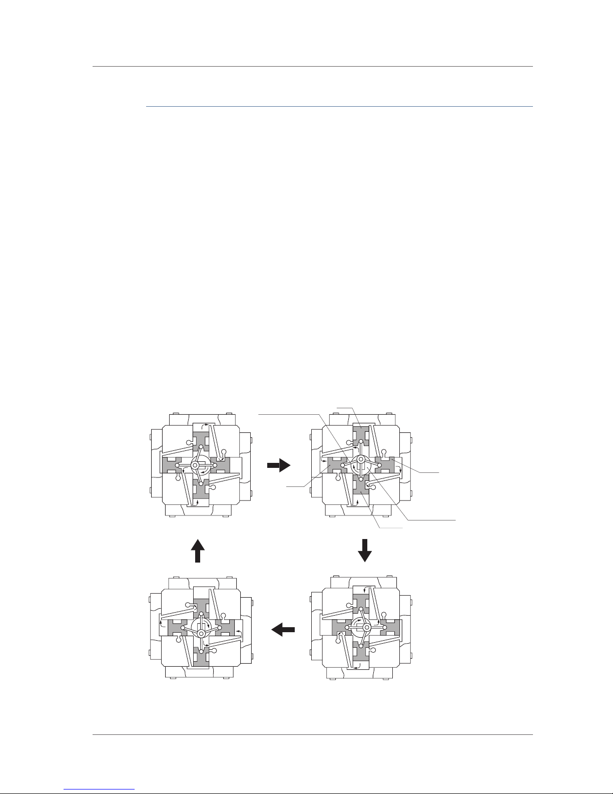
1.2 Structure and operating principle
4 pistons are installed in a radial fashion on the ow rate detecting part of the equipment where they repeat a back
and forth motion with the liquid owing in and out of the inlet/outlet. The movement of pistons is converted to a rotating
motion by the crank shaft and transfered to the rotation detecting part.
Then, a pulse signal corresponding to movement amount of the pistons is generated by the rotary encoder of the
rotation detecting part and the instantaneous value or accumulated ow rate are displayed on the calculated display
section of the Ono Sokki DF-2200 On-Board Flow Meter or the FM Series Digital Flowmeter.
The output pulse signal consists a pair of pulses with different phases so that the rotation direction can be recognized.
Because of that, correct measurement is possible regardless of whether the ows are reversed or pulsed.
E4
P4
E3
P3
E2
P2
P1
E1
(a) (b)
(c)
(d)
Connecting rod
Crank shaft
PST1
PST3
PST2
PST4
E1 to 4:Port to connect to flowmeter outlet
PTS1 to 4: Piston 1 to 4
P1 to 4:Port to connect to head cylinder of pistons 1 to 4ؙ

8
System Conguration
2. System Conguration
Congure the system according to your intended use and purpose, referring to the table below.
- Display Unit -
●FM-1500 Digital Flowmeter
●FM-2500A Digital Flowmeter
●DF-2200 On-Board Flow Meter
FP-4135 On-Board Volumetric Flow Detector -
(flow detecting part)
Temperature detector (straight out from cable 2 m)
Flow Detector (straight out from cable 2 m)
Temperature signal cable
Flow Signal Cable
Connector
Model name of temperature signal cable Full length
FP-0025 5 m
FP-0026 10 m
FP-0027 20 m
Model name of flow signal cable Full length
FP-0015 5 m
FP-0016 10 m
FP-0017 20 m
POWER
PRINT SETUP L / g
DENS/CD
INSTANT TOTAL/LAPRESET STOP
HOLD
START
ESC
NEXT ENTER
>>
䠚
䠚
FZ-ONLY
FM-1500
Flow Meter
POWER
1
2
DISP COND
3
MENU
ESC ENTER
RESET START
HOLD
STOP
MEAS
DISP
ALL
DISP
LOCAL
FM-2500A
Flow Meter
*1: FP-4135 On-Board Volumetric Flow Detector does not come with a pressure sensor. If you need to measure pressure, please contact
the nearest Ono Sokki sales office or the distributor where you purchased the product.
*2: It is an optional function.
FP-4135 On-Board Volumetric Flow Detector-
(signal processing part)
Model name FM-2500A + DF-0400A
Measuring item Instantaneous flow rate/
Accumulated flow rate/
Accumulated time/
Temperature/Pressure*
1
Output signal Analogue pulse/RS-232C/GP-IB*
2
Model name DF-2200
Measuring item Instantaneous flow rate/
Accumulated flow rate/
Accumulated time/
Temperature/Pressure*
1
Output signal Analogue pulse/CAN/RS-232C*
2
Model name FM-1500 + DF-0400A
Measuring item Instantaneous flow rate/
Accumulated flow rate/
Accumulated time/
Temperature/Pressure*
1
Output signal Analogue pulse/RS-232C/GP-IB*
2
• For some measurement targets, you might need detectors other than the FP-4135 On-Board Volumetric Flow Detector.
For details, contact the nearest Ono Sokki sales ofce or the distributor where you purchased the product.
• The FP-4135 On-Board Volumetric Flow Detector is separated into a ow detecting part and a signal processing part.
• The FM Series Digital Flowmeter requires the detecting module DF-0400A.
• FP-4135 On-Board Volumetric Flow Detector does not come with a pressure sensor. If you need to measure pressure,
please contact the nearest Ono Sokki sales ofce or the distributor where you purchased the product.
!
CAUTION
 Loading...