

ONOSOKKI DS 0297, DS 2104 User Manual

DS-2000 Series
Sound Level Measurement
ONO SOKKI CO., LTD.
Equipment Name
Model Name
Qty.
Remarks
AC power adapter for main unit
1
With AC cable
1
AC power adapter for notebook PC
1
With AC cable
Soft protection key
1
Preamplifier for microphone
MI-3110
1
Rotation sensor
HT-5200
1
Table tap
1
3 outlets or more
BNC mini-mini type jack cable
1
Between DS-2104 and HT-5200
Sound Level Measurement
Target: Measurement of sound level generated from a drive unit having a gear under a steady
Purpose: Measurement of sound level
Equipment:
Main unit DS-2104 1
Notebook PC
I/F card/cable DS-0297 1
operating condition and a condition where the number of rotations is dynamically changed.
How much is level variation?
What should be done as noise reduction measures?
Microphone MI-1233 1
Sound pressure calibrator SC-3120 1
Tripod
Both-ends BNC cable
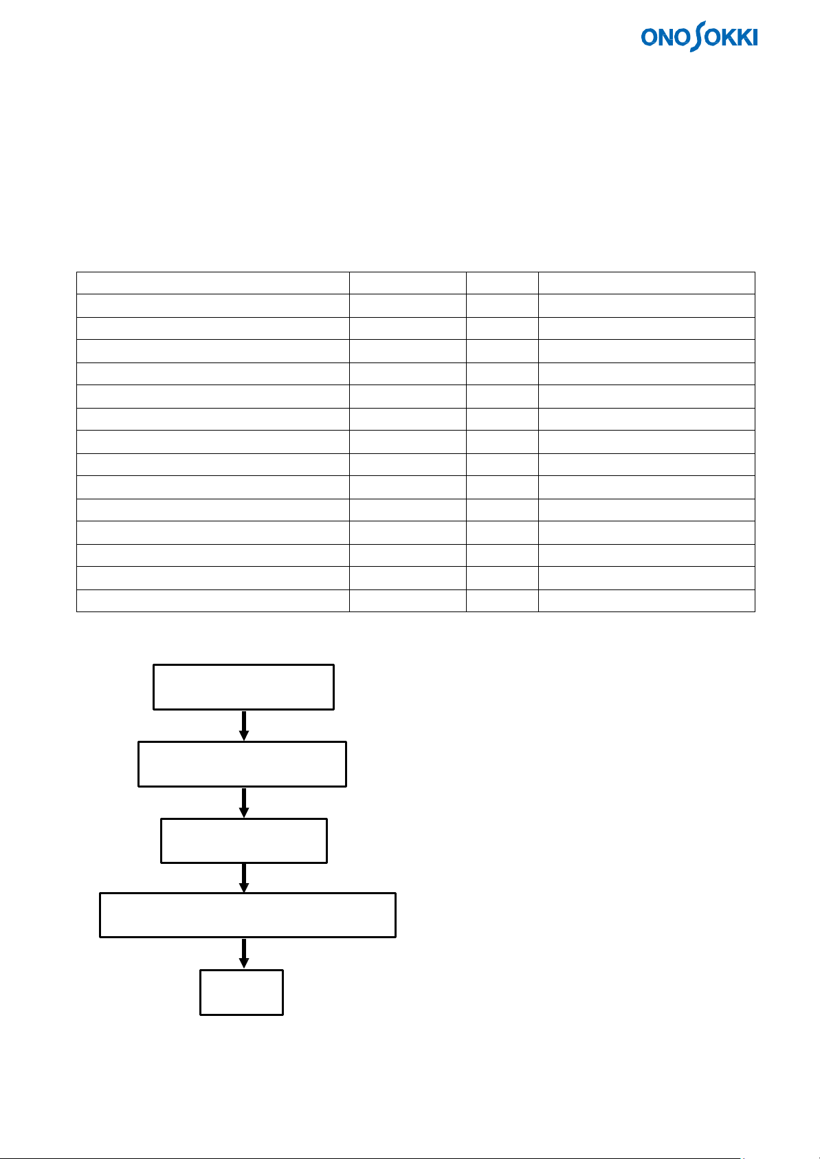
Measurement procedure:
1. Device connection
2. Device activation/check
3. Sensor calibration
4. Measurement, analysis, data storage
5. End
2 For microphone/rotation sensor
1 Between DS-2104 and MI-3110
1
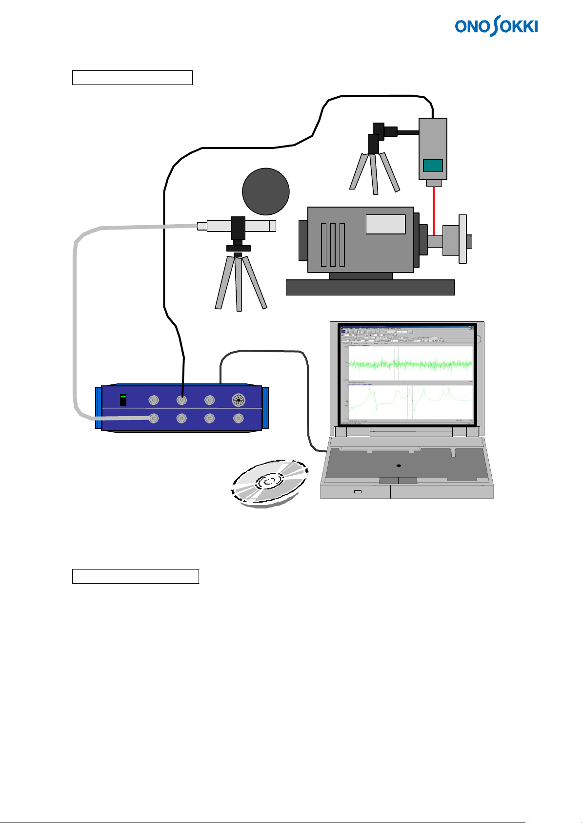
1. Connecting Devices
1-1. Connection Diagram
1-2. Connection Procedure
(1) Connect the power adapter to the personal computer.
(2) Connect the power adapter to the DS-2000.
(3) Insert the protection ke y into the personal computer.
(4) Connect the interface (ONOLINK II (Card)) between the personal computer and the DS-2000.
(5) Connect the both-ends BNC cable between the measurement microphone and the DS-2000 Ch1 input.
(6) Connect the signal cable between HT-5200 and EXT Sample of the DS-2000.
2
2. Activating and Checking Devices
2-1. Turning the Power On
(1) Set the power switch on the front panel of theDS-2000 to the upper position.
The green lamp of the switch lights up.
(2) Turn on the power of the personal computer.
The Windows OS starts.
(3) Turn on the power of the HT-5200.
The LCD turns on.
2-2. Activating DS-2000
(1) Double-click the DS-0221FFT icon on the desktop.
(2) Maximize the window size (both inner and outer windows).
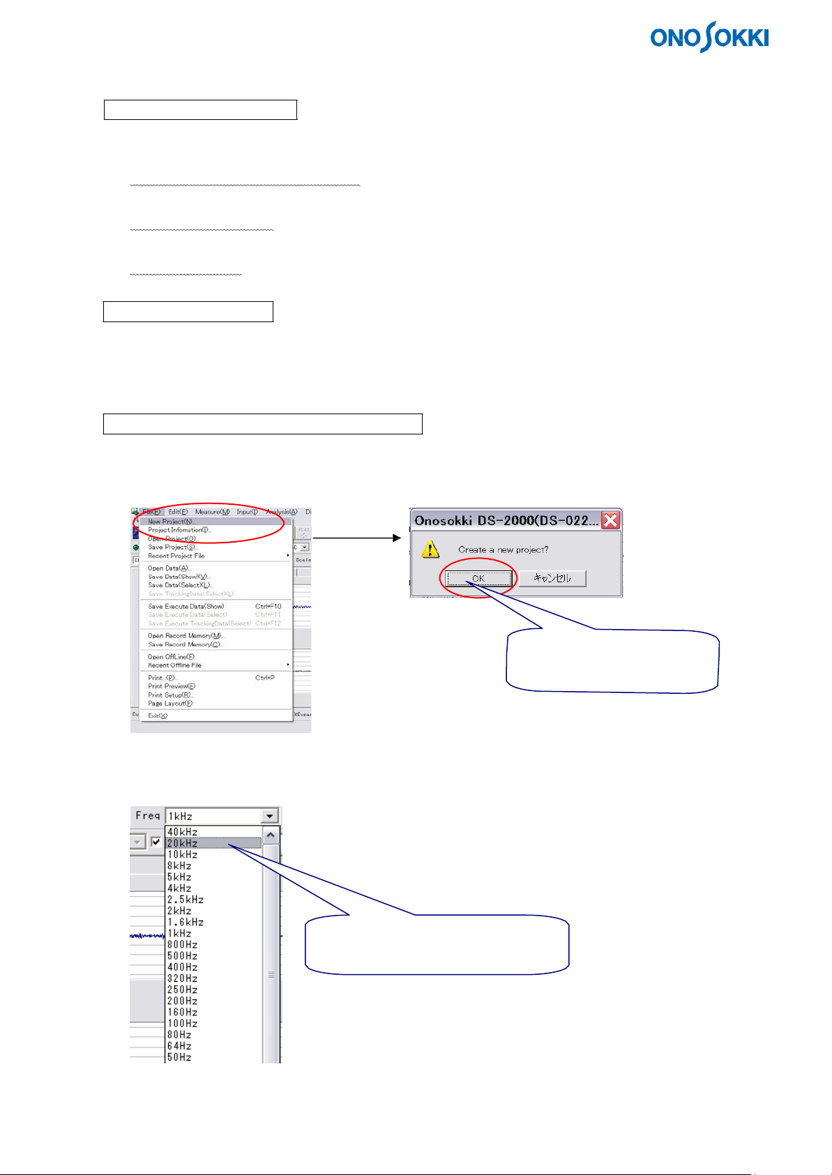
2-3. Checking DS-2000 and Setting Conditions
(1) Setting to initial conditions
Select New Project from the File menu.
(2) Setting a frequency range
Use the Freq tool bar.
Select an upper limit of analysis
frequency from this drop-down list.
Click OK to set FFT analysis
initial conditions.
3
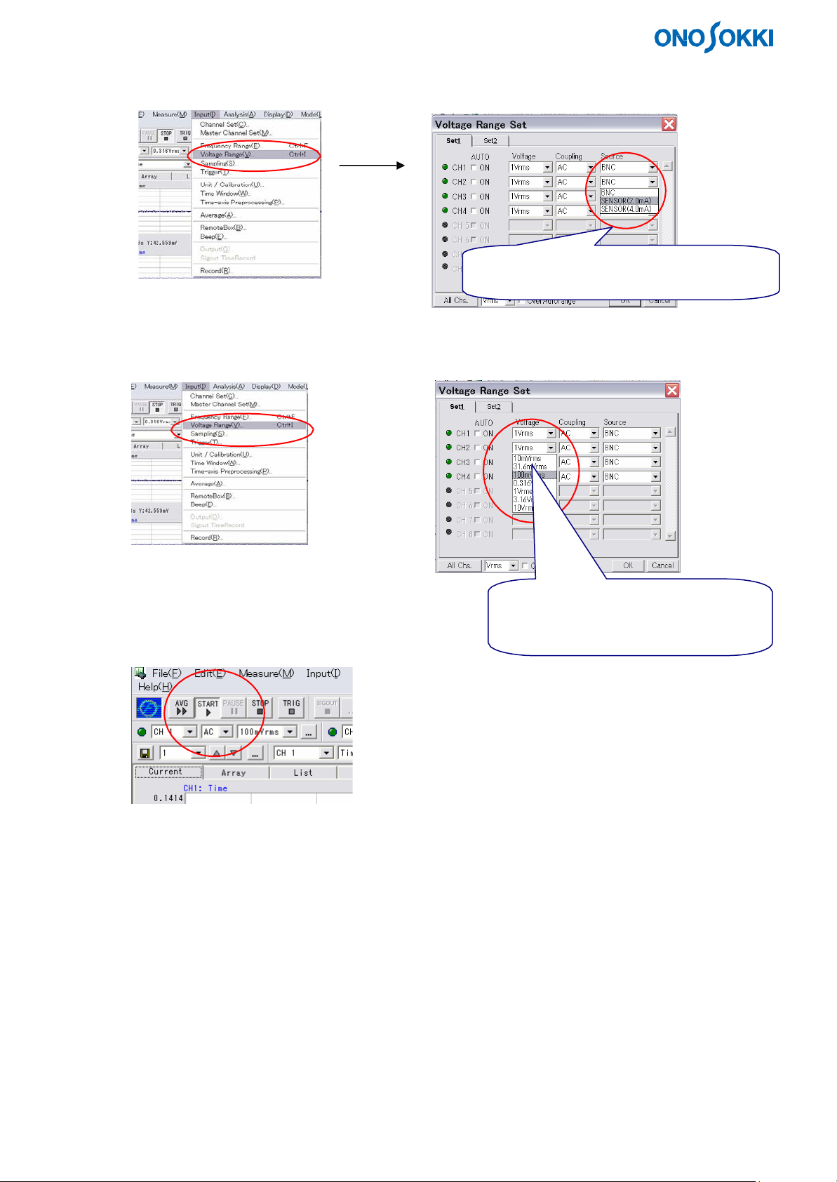
(3) Setting an input source
Select Voltage Range from the Input menu.
(4) Set an input voltage range.
Select Voltage Range from the Input menu.
(5) Start data sampling.
Click the ">" tool button.
Set SENSOR(2.0mA) as a signal from
MI-3110 (BNC in the case of voltage input).
Select a minimum value with which the
OVER LED does not light up, from this
drop-down list.
4
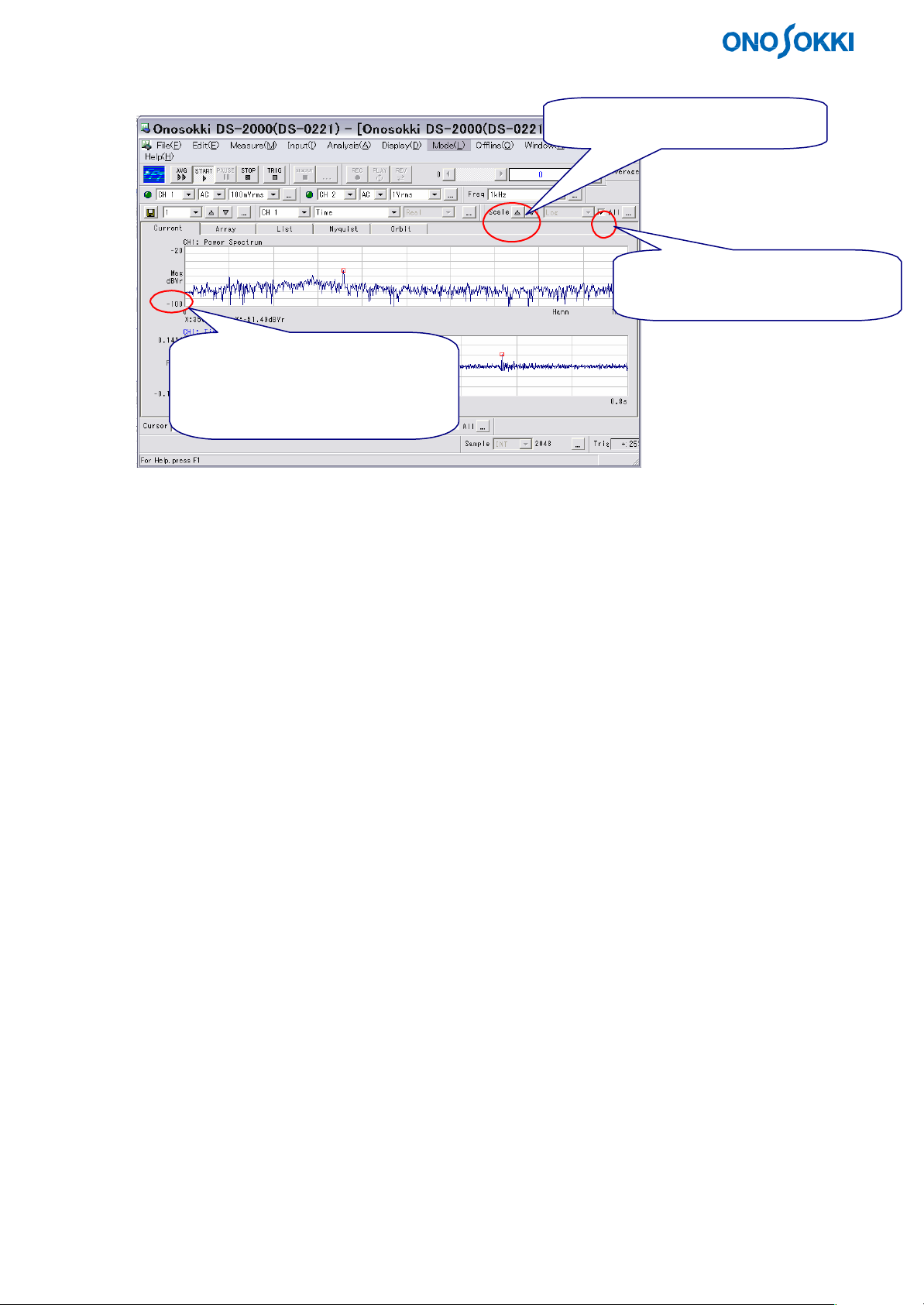
(6) Change the display gain.
Use the tool bar.
Click these buttons (△ and ▽).
Clicking △ decreases this value
(magnifies small data).
Clicking ▽ increases this value
(small data is not displayed).
Make sure that the signal from the sensor (microphone) can be correctly analyzed.
When checked, all the displayed
scales will be changed.
5
 Loading...