

ONNLINE ESSENSSE Instruction Manual
ONNLINE ESSENSSE
onnline®
Instruction manual 3
25
47
Käyttöohje
Bruksanvisning
P01-0210-0514-ON
H01-0210-0514-ON
1/2
4
S01-SAFE-0614-ON
2/2

3
EN
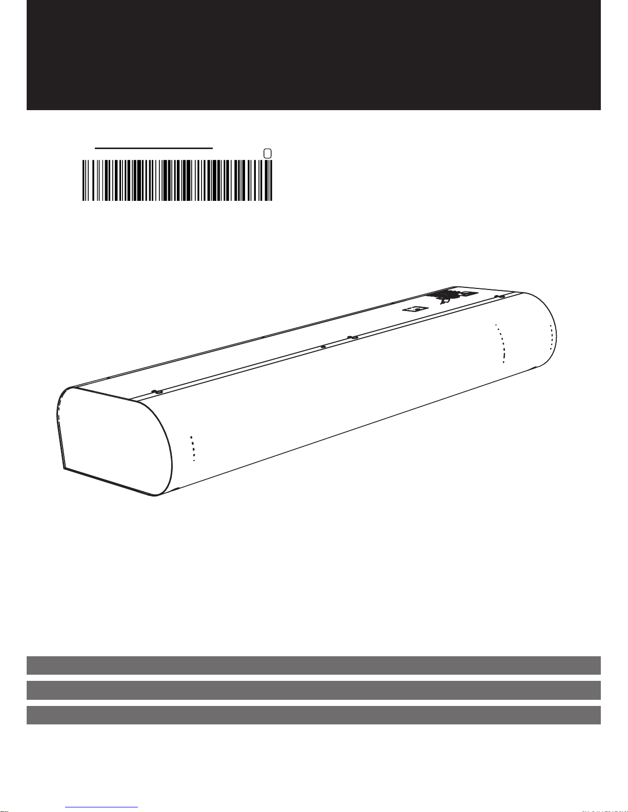
INSTRUCTION MANUAL
AIR CURTAIN
4
Before installation, thoroughly study the part Safe use of air curtains, where you will nd all the instructions for
the safe and correct use of the product.
This user‘s manual includes important instructions for the correct installation of an air curtain. Carefully read and adhere to all the
following instructions before installing the air curtain! The manufacturer reserves the right to make changes including to the technical documentation without prior notice. Keep the user‘s manual for future use. Consider the instructions in the user‘s manual as
a part of the product
EC DECLARATION OF CONFORMITY
The product was designed, produced and introduced on the market, fulls all respective provisions and is in accordance with the
requirements of the regulations of the European parliament and the Council, including any modications under which it was classied. Under the terms of usual use stated in the user and installation manual, the product is safe. Harmonized European standards
were used during assement as stated in the respective EC Declaration of Conformity. The actual and full version of the EC declaration of Conformity in at www.2vv.cz and on the enclosed CD.
Symbol Meaning
ATTENTION!
DO NOT MISS!
YOU WILL NEED
TECHNICAL INFORMATION
Warning or notice
Important instructions
Practical tips and information
Further detailed technical information
Reference to another section
/part of the instruction manual
1. BEFORE YOU BEGIN
5
DO NOT MISS!
• In the event that the ventilation unit was transported in a
temperature lower than 0 °C, it is necessary to leave the
unit for at least 2 hours without turning it on, allowing the
temperature inside the unit to be levelled to the temperature of the surrounding area.
2. UNPACKING
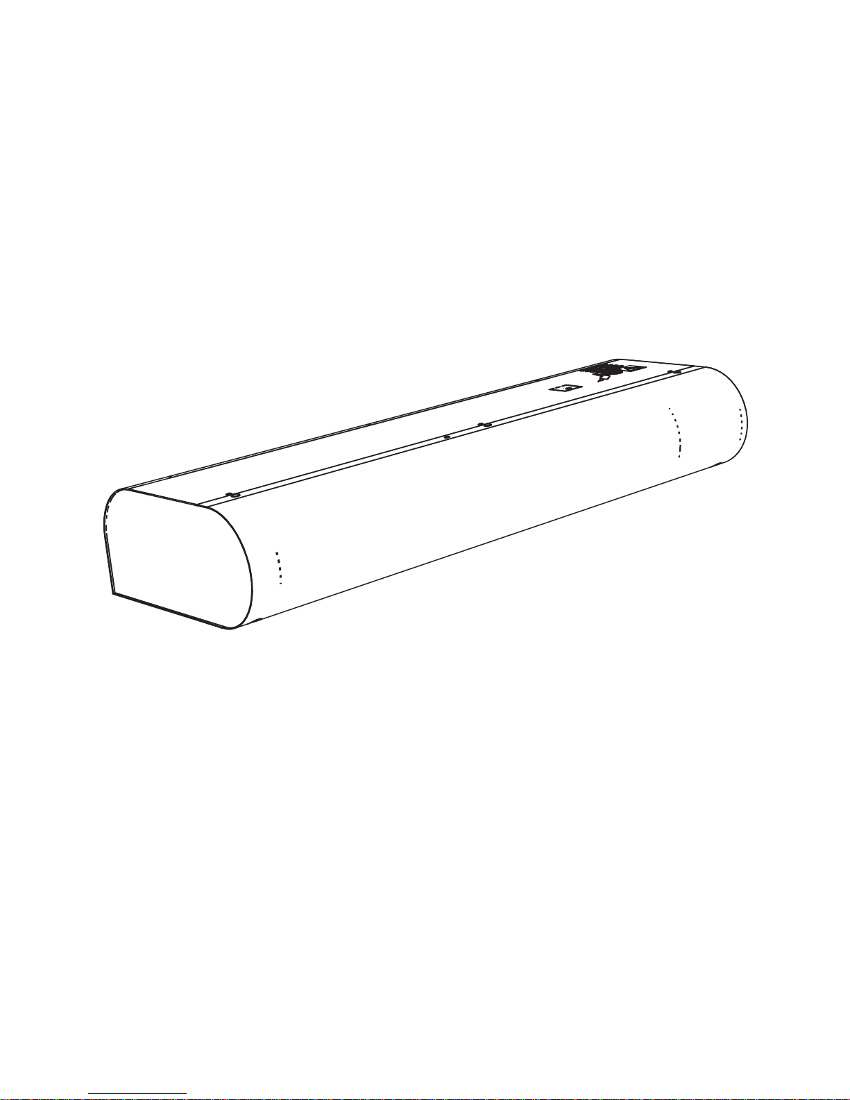
3. MAIN PARTS
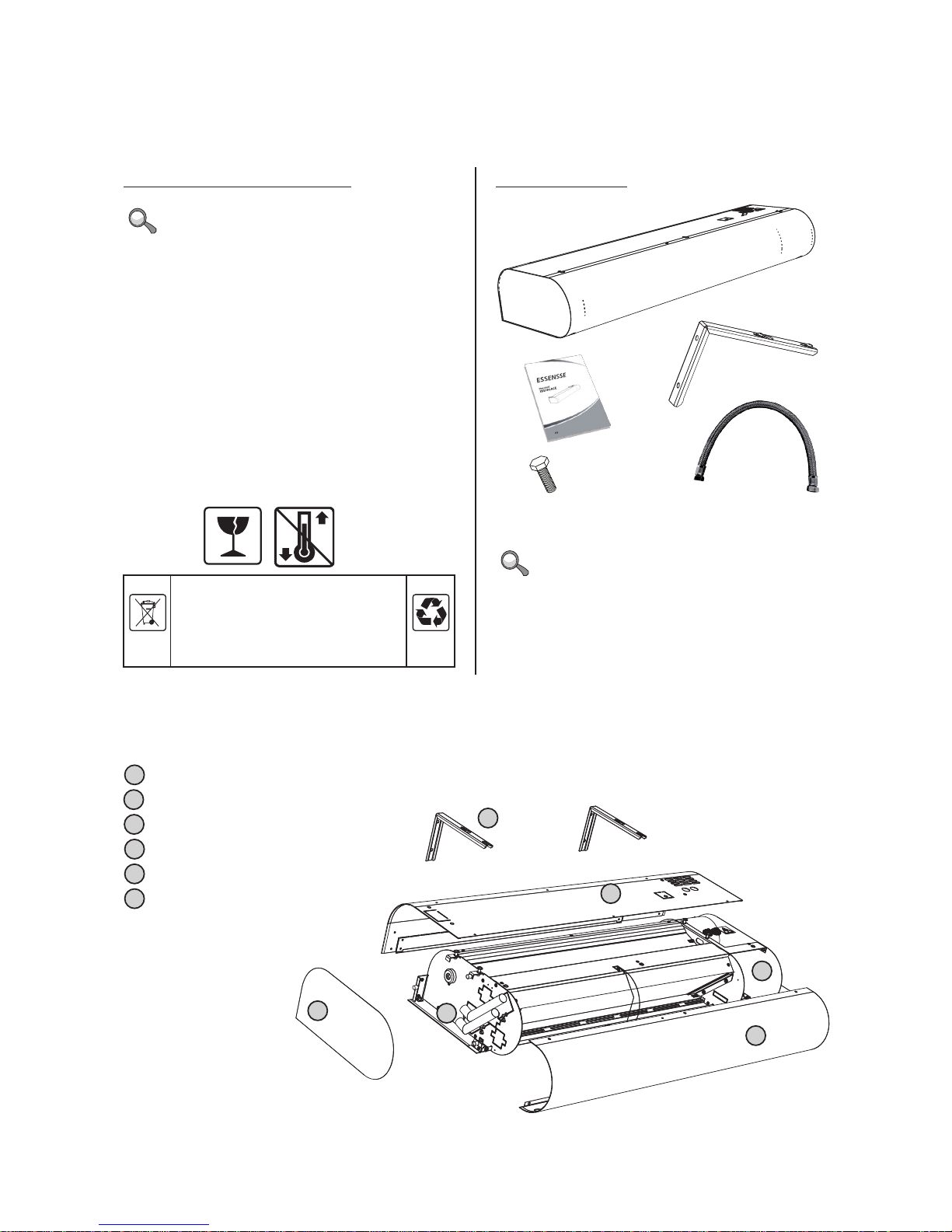
2.1 CHECK THE DELIVERY
DO NOT MISS!
Check immediately after delivery that the packed product
has not been damaged. If the packaging is damaged inform
the carrier. If the complaint is not lodged in time, no future
demands can be claimed.
• Check that the product type is the same as you ordered. In
the case of an irregularity do not unpack the air curtain and
immediately report the fault to the supplier.
• After unpacking, check that the air curtain and other parts
are in order. If in doubt contact the supplier.
• Never install a damaged air curtain!
• If you are not going to unpack the air curtain immediately
after delivery, it must be stored in a dry indoor environment
with an ambient temperature between +5 °C and +40 °C.
2.2 CONTENTS
+5 oC
+40
o
C
All used packaging materials are ecological and can be reused or recycled. Actively contribute to the protection of the environment by properly disposing of and
recycling packaging materials.
2x
2x
1x
4x M6x20
1
1
2
2
3
3
4
4
5
5
6
6
Mounting brackets
Top cover
Area for connecting the regulation module
Suction cover
Connection for water heat exchanger (only on water versions)
Side cover (attached magnetically)
VCE-x-xxx-V only
6
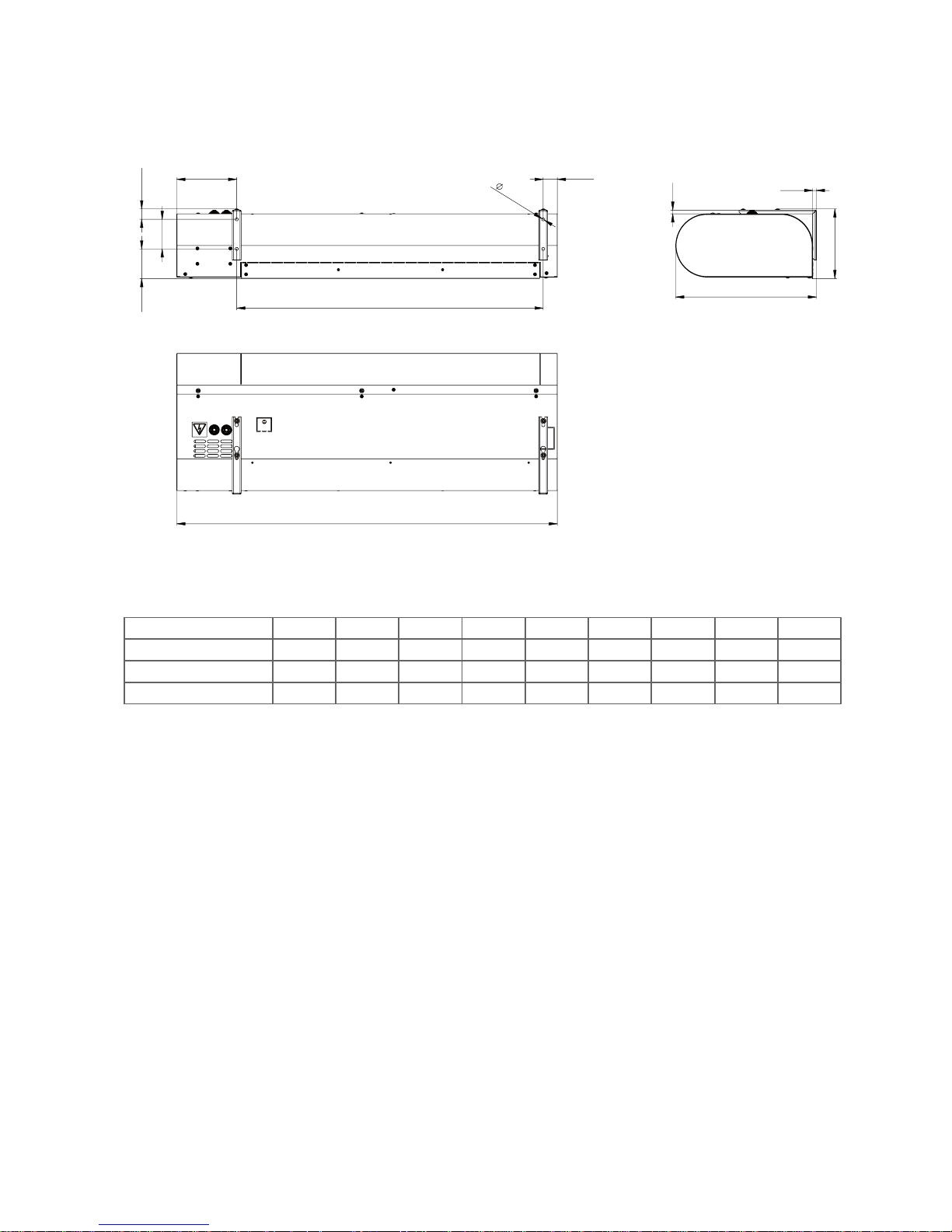
4. DIMENSIONS
A
C
D
E
G
H
I
F
8
B
10
10
Type A B C D E F G H I
VCE-B-100-X-... 829 1030 381 189 29 80 80 163 38
VCE-B-150-X-... 1330 1530 381 189 29 80 80 163 38
VCE-B-200-X-... 1830 2030 381 189 29 80 80 163 38
The tube diameters for connecting the water heat exchanger are G1/2“.

7
5. TECHNICAL PARAMETERS
Type
Recommended
installation height
[m]*
Air output
[m/h]
Acoustic pressure
[dB(A)]**
Heater power
output [kW]***
Total
consumption
[V/A]
Motor
con-
sumption
[V/A]
Tempera-
ture
increase
t [°C]***
Power
supply
frequency
[Hz]
Weight
[kg]****
1st level 2nd level
Speed 3 Speed 2 Speed 1 3m 5m
VCE-B-100-E-...
3
1450 1320 1120 55,9 51,5 5,9 400/10,2 230/0,6 12 50 16 16
VCE-B-150-E-... 2150 1860 1500 57,0 52,6 10,0 400/15,9 230/0,7 15 50 22 22
VCE-B-200-E-... 2800 1160 1770 57,5 53,0 12,5 400/19,6 230/0,8 14 50 27 27
VCE-B-100-V-... 1300 1190 1010 55,8 51,3 9,6 230/0,6 230/0,6 24 50 17 17
VCE-B-150-V-... 1900 1720 1410 54,4 49,9 15,7 230/0,7 230/0,7 26 50 23 23
VCE-B-200-V-... 2550 2160 1730 541 49,7 22,4 230/0,8 230/0,8 27 50 28 28
VCE-B-100-S-... 1500 1340 1140 56,5 52,0 - 230/0,6 230/0,6 - 50 15 15
VCE-B-150-S-... 2200 1880 1530 58,6 54,2 - 230/0,7 230/0,7 - 50 20 20
VCE-B-200-S-... 2900 2290 1800 57,7 53,2 - 230/0,8 230/0,8 - 50 24 24
VCE-B-100-F-... 1450 1320 1120 55,9 51,5 9,4 400/14,0 230/0,6 21 50 16 16
VCE-B-150-F-... 2150 1860 1500 57,0 52,6 15,1 400/22,8 230/0,7 22 50 22 22
VCE-B-200-F-... 2800 2260 1770 57,5 53,0 19,1 400/28,3 230/0,8 20 50 27 27
VCE-B-100-G-... 1450 1320 1120 55,9 51,5 4,7 400/ 7,4 230/0,6 10 50 16 16
VCE-B-150-G-... 2150 1860 1500 57,0 52,6 7,6 400/11,6 230/0,7 11 50 22 22
VCE-B-200-G-... 2800 2260 1770 57,5 53,0 9,6 400/14,6 230/0,8 10 50 27 27
* Maximum recommended installation height suitable for most applications (may dier based on the existing conditions at the installation location).
** Acoustic pressure measured at 3 and 5 m away from the device at maximum motor speed. Direction coecient Q: 2.
*** Suction air temperature +18°C, at maximum heating level (90/70 for water) and highest fan speed.
**** Weight without regulation.

8
Type Air output
[m3/h]
Heating output
[kW]
Temperature at exhaust
[°C]
Pressure loss
[kPa]
VCE-B-100-V-... 1300 9,6 42,3 0,5
VCE-B-150-V-... 1900 15,7 44,9 2,6
VCE-B-200-V-... 2550 22,4 46,6 3,2
Air curtain with a water heat exchanger for a water temperature gradient of 90/70 °C
and a suction air temperature of +18 °C.
Type Air output
[m3/h]
Heating output
[kW]
Temperature at exhaust
[°C]
Pressure loss
[kPa]
VCE-B-100-V-... 1300 8,0 37,9 0,4
VCE-B-150-V-... 1900 13,0 40,0 2,0
VCE-B-200-V-... 2550 18,6 41,4 2,2
Air curtain with a water heat exchanger for a water temperature gradient of 80/60 °C
and a suction air temperature of +18 °C.
5. TECHNICAL PARAMETERS
6. INSTALLATION
6.1 OPERATING CONDITIONS:
The air curtain is designed to be operated in a dry indoor environment at an ambient temperature in the range from 5°C
to +40°C and at a relative humidity of up to 80%, for transporting air that is free of dust, fats, chemical emissions and other
pollutants. The electrical protection rating of the air curtain is
IP 20 (protection against bodies larger than 12.5 mm, not protected against water). Air curtains with an electric heater are
tted with an operating thermostat with an automatic reset
(located on every heating element) and an emergency thermostat with a manual reset. The hot water heat exchangers
are intended for a maximum operating water temperature of
+100°C and a maximum operating pressure of 1.6 MPa. The
air curtain design must always be drawn up by a HVAC and
central heating project engineer.
6.2 INSTALLATION CONDITIONS:
The installation and assembly of an air curtain may only be
carried out by a person with relevant qualications, that has
suitable tools and equipment at their disposal. The air curtain
is supplied with 2x mounting brackets bolted to the top part
of the curtain‘s case as standard. If you wish to install the curtain on threaded rods, it is necessary to order this separately.
For the correct function of the curtain, you should adhere to
the following rules:
Type Air output
[m3/h]
Heating output
[kW]
Temperature at exhaust
[°C]
Pressure loss
[kPa]
VCE-B-100-V-... 1300 6,3 33,6 0,2
VCE-B-150-V-... 1900 10,3 35,2 1,5
VCE-B-200-V-... 2550 14,8 36,4 1,4
Air curtain with a water heat exchanger for a water temperature gradient of 70/50 °C
and a suction air temperature of +18 °C.
Type Air output
[m3/h]
Heating output
[kW]
Temperature at exhaust
[°C]
Pressure loss
[kPa]
VCE-B-100-V-... 1300 4,7 29,5 0,2
VCE-B-150-V-... 1900 7,7 30,7 1,0
VCE-B-200-V-... 2550 12,2 31,5 0,8
Air curtain with a water heat exchanger for a water temperature gradient of 60/40 °C
and a suction air temperature of +18 °C .
The warm water heat exchanger made from Cu/Al materials is intended for a max. operating water
temperature of +100 °C and a max. operating pressure of 1.6 MPa.
9
6. INSTALLATION
6.3 AIR CURTAIN
INSTALLATION PROCEDURE:
1. Installation of the exible supply hose
- only on the water version
• It is recommended to use exible hoses for connecting the
water heater.
• The connection and pressure tests of the heater must be
carried out by a person qualied in the eld of plumbing,
who must at all times adhere to the valid norms and regulations of the given country.
• The heater is designed to use water with a maximum pre-
ssure of 1.6 MPa and a maximum temperature of +100 °C.
• Install exible pipe before installing the brackets.
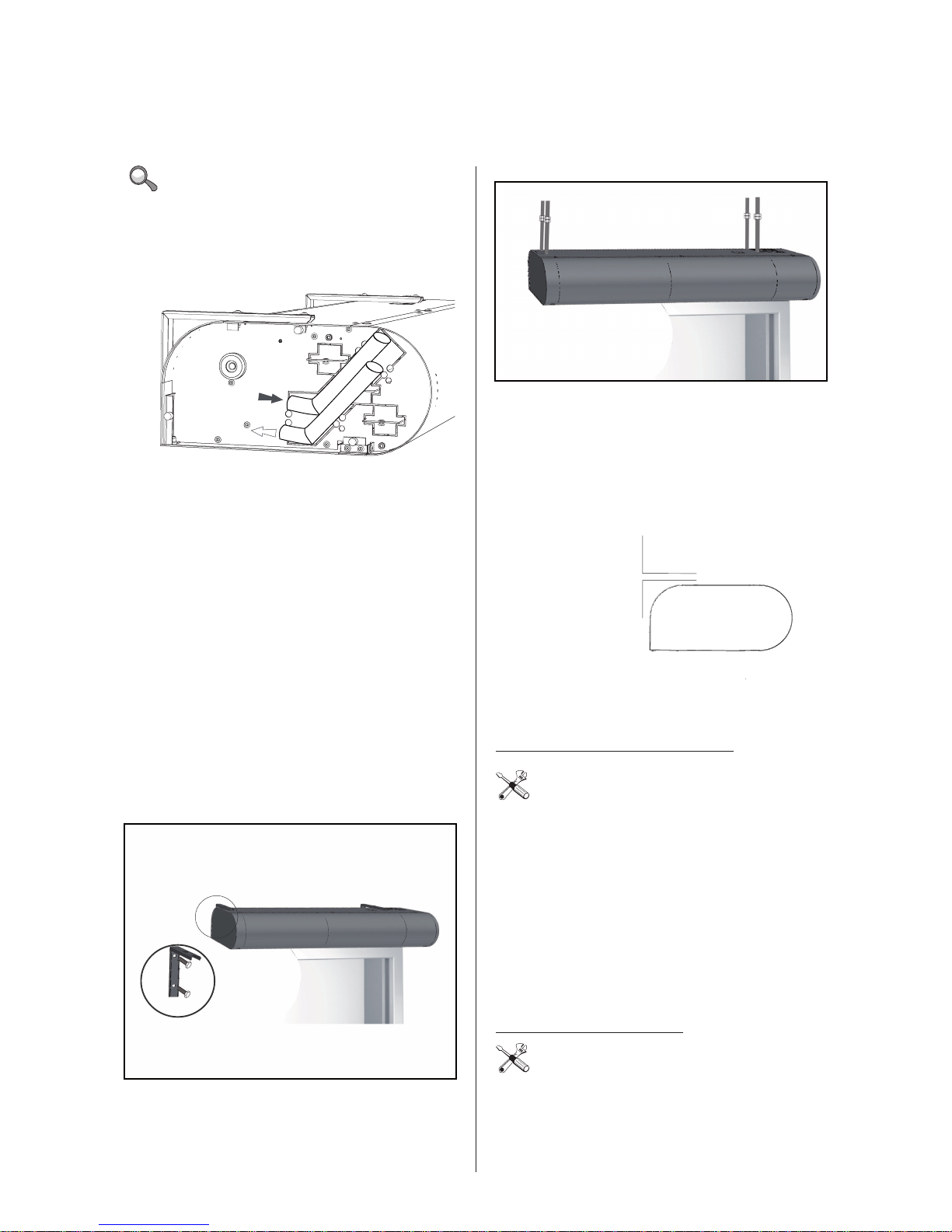
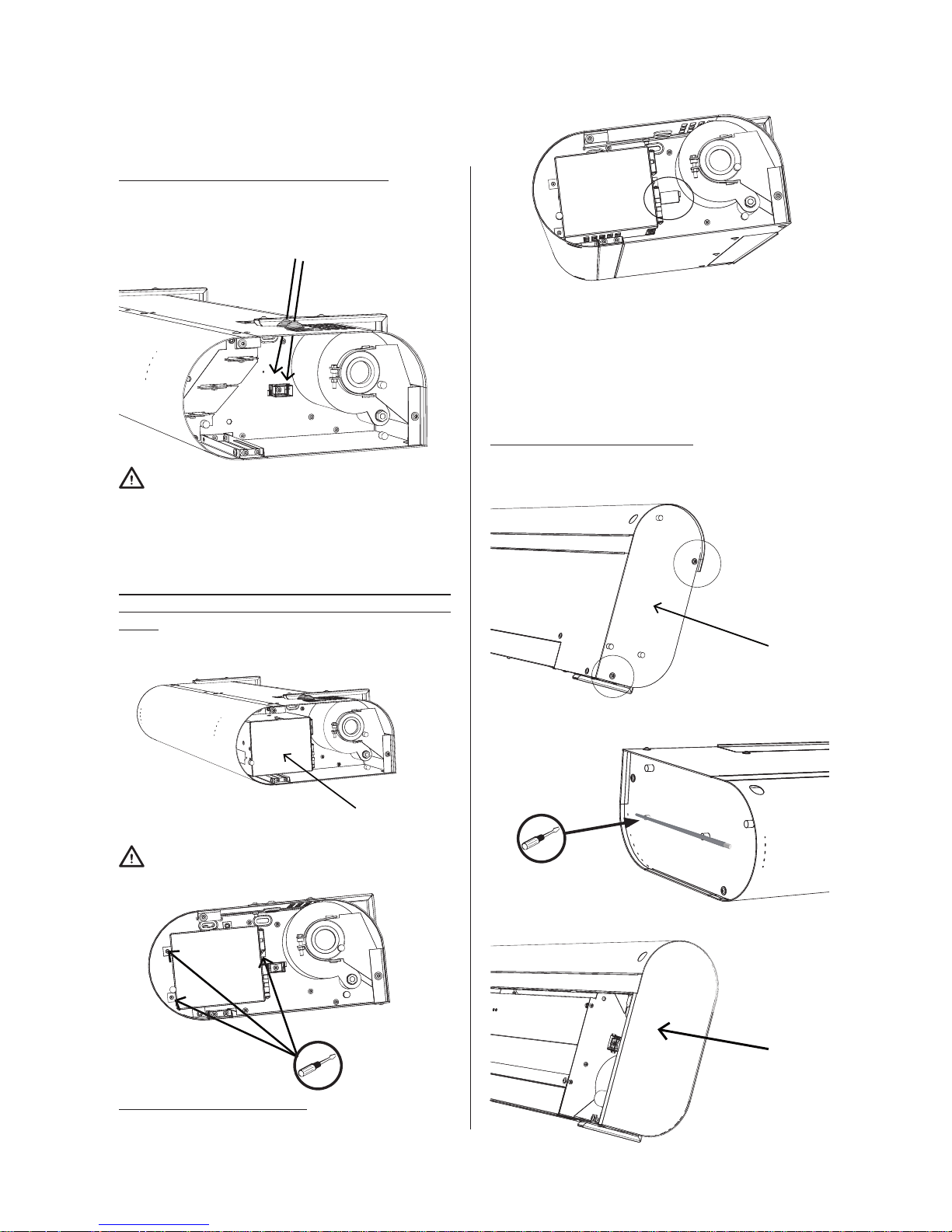
2. Installation Procedure
1. screw out the screws of the bottom cover and remove the
cover
2. remove the side panel by pulling to the side
3. bend the metal sheet as shown in the picture; pull the
included water supply hoses through the created opening.
Connect the hoses and close the side cover.
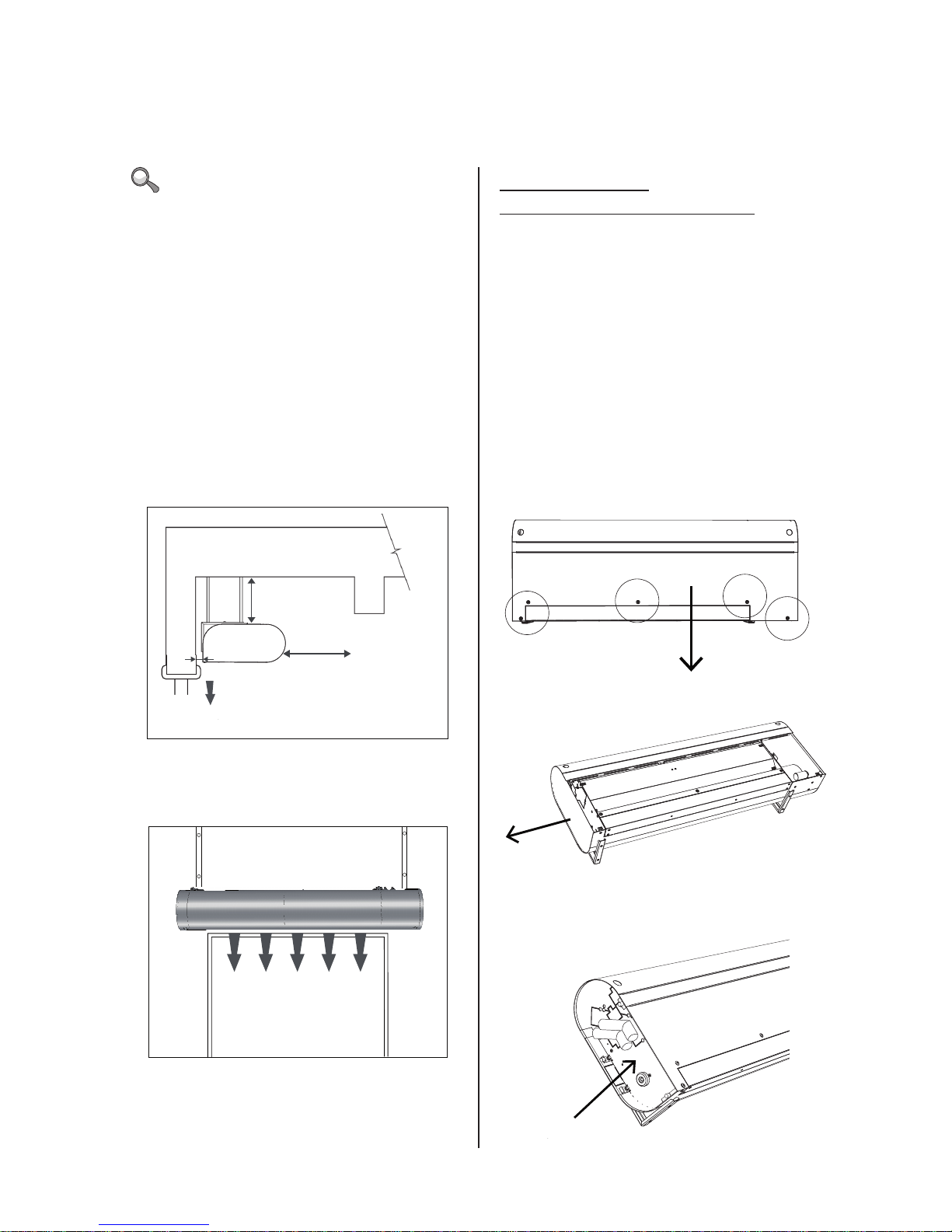
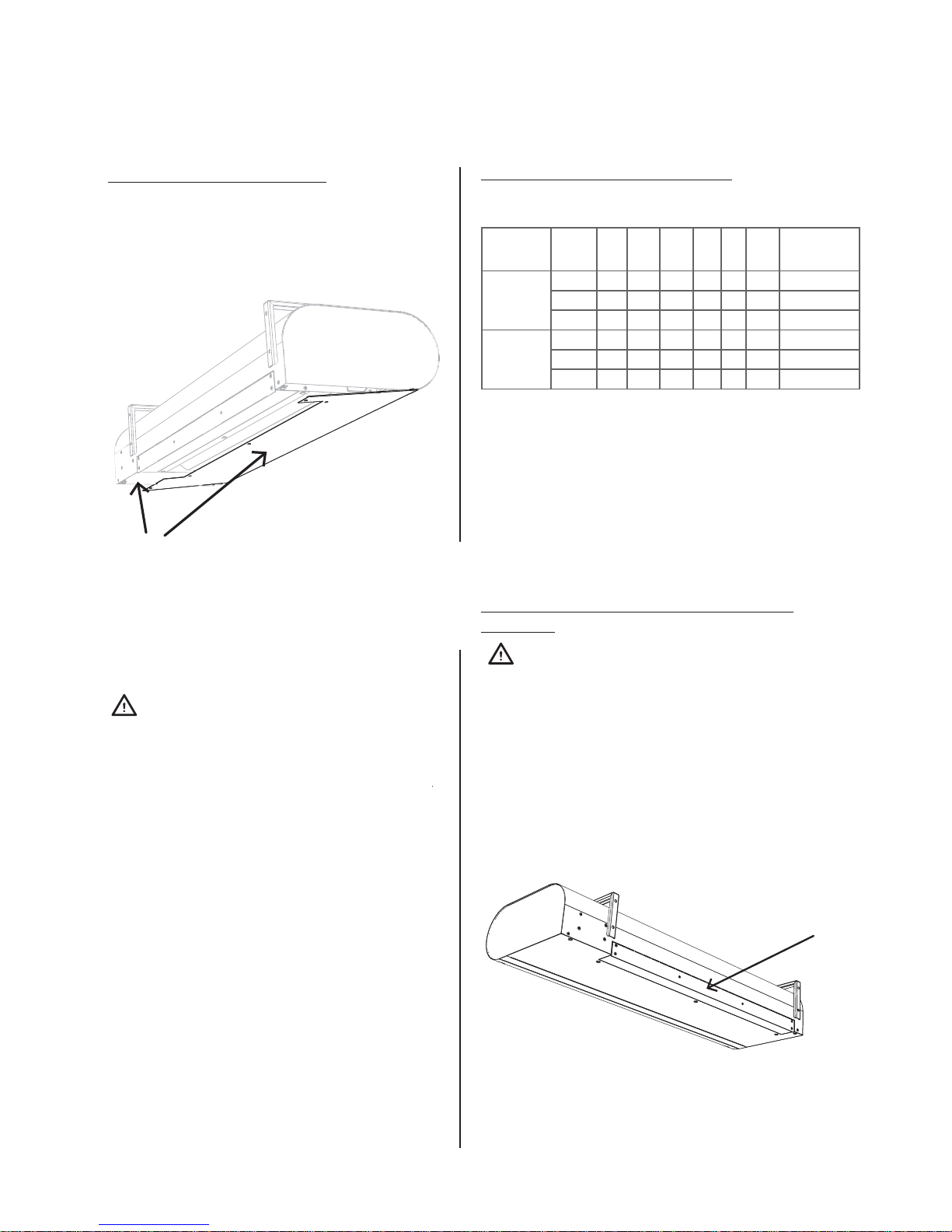
DO NOT MISS!
• The minimum air curtain clearance distances must be ad-
hered to (see. picture - clearance distances) with respect to
the ammability of materials.
• The clearance distances with respect to the ammability
of materials is determined by the project engineer of the
given project, respecting the valid codes at the installation
location of the air curtain.
• The curtain can only be installed in a horizontal positi-
on.
• For the curtain to operate properly, there must be at least
200 mm of free space in front of the suction inlet cover.
• The exhaust of the curtain should be located as close as
possible to the door or curtained opening.
• the curtain should overlap the curtained opening on both
sides by at least 100mm.
• If you install the curtain above a door, locate it as close as
possible to the top edge of the door. Make sure that neither
the suction nor the exhaust is shielded by anything and
that the airow can travel freely into the room, see Picture.
min. 200 mm
min. 100 mm
min. 50 mm*
* if the conditions require a greater foreblow than normal, then it is necessary to maintain a clearance of at
least 50 mm from the wall to enable movement.
10
6. INSTALLATION
DO NOT MISS!
•
• connect the pipes in an counterow connection arrange-
ment, the connection of the hot heating water and the return heating water is shown in the picture (picture below).
• We recommend that you attach shut-o ttings on to the
inlet and outlet of the heater to make it possible to shut-o
the water
3. Hanging the curtain in the installation
position
Measure out the installation holes, measure out the dimensions and prepare the curtain mounts - see the Dimensions
table on page 4.
The curtain must be installed in such a way that the bottom
edge of the curtain is as close as possible to the edge of the
door. Adhere to the minimum clearance distances during installation.
The curtain can normally be installed in two ways:
1. use the installation brackets and mount it on the wall.
2. hang it on threaded rods.
Normally the curtain is hung on the installation brackets above the door if the installation location permits. When using
the brackets you have the following options:
a - it can be used in the case, where there is at least 15 cm
above the curtain and the user does not mind that the brackets are visible.
b - it gives the option for installation in the case of a small
clearance above the curtain (however, at least 5 cm). In that
case the brackets are not visible.
If there is a ventilation window above the door or another
material preventing the installation of a bracket, it is possible
to use threaded rods and to suspend the curtain from the ceiling connecting directly into dowels (see further in the text).
Installation using the mounting brackets
YOU WILL NEED
4x dowels (not included)
4x bolts (not included)
Screw o the brackets and according to the dimension diagram (see „Dimensions“) measure out the holes on the wall
(adhere to the installation rules). Remember that it is necessary to choose, whether you will install the curtain according to
A or B and based on this set the height of the holes! Screw the
bolts that were used for attachment to the bracket back into
the holes in the curtain (only partially into the curtain) and
hang the curtain on these bolts. Check the that the curtain
is properly secured so that the curtain does not fall out
accidentally.
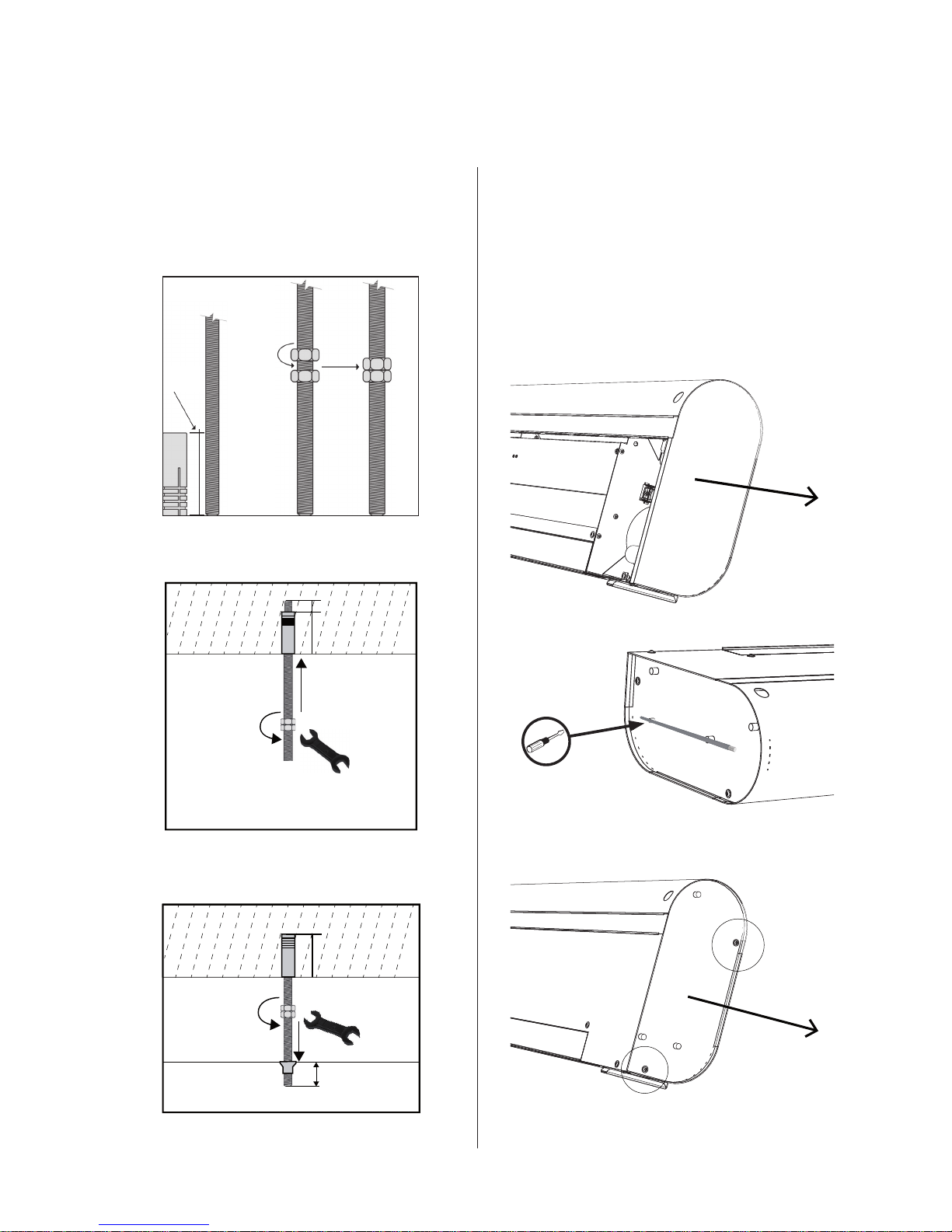
Installation using threaded rods
YOU WILL NEED
4x anchor 6mm (not included)
4x threaded rod M6 (not included)
8x nut M6 (not included)
Wrench M10 (not included)
A
B
11
6. INSTALLATION
Before the actual installation, check that the ceiling structure
has the carrying capacity to hold the weight of the curtain.
Perform the installation according to the following pictures.
1. Attachment to the ceiling
2. Attachment to the curtain
4. Installation of the regulation module
(you will nd detailed instructions in the
handbook for the given regulation module)
The following procedure requires the bottom cover to be removed
4.1 remove the designated side panel, which is magnetically
attached from the side of the motor
4.2. using a size M5 Allen key, remove the designated bolts
and take o the inner side panel
30mm
10mm
30mm
4x
30mm
10mm
12
4.3. Pulling the supply cables through
Pull a sucient length of power cable through into the unit.
Pull through the communications cable if you will use the DM
regulation module.
Pull through the cables for accessories, if used.
ATTENTION!
The power cable must be determined by the project engineer in the given building, it must conform to valid
norms and codes and must respect the performance and
installation parameters of the curtain.
4.4. Installation of the regulation module (the
regulation module is not included with the curtain)
1. insert the appropriate regulation module into the unit
2. fasten 3x self-tapping bolts M5 using an Allen key M5 (the
bolts are included in the regulation module package)
ATTENTION!
You need an extension attachment at least 20cm long
4.5. Connecting the cables
6.1. secure the electrical power cord in the pull reduction
elements
6.2. connect together the TYCO connectors
6.3 connect together the switching elements and if appro
priate the DM regulation module, connect the communi
cation cable
6.4 nally connect the power cable as shown in the connection diagram
4.6. Installation of partitions
1. Attach the inner side panel and screw in the designated
screws using a size M5 Allen key
2. return the magnets to their original position + attach tool
3. put the designated side panel back in its place
6. INSTALLATION
1
2
13
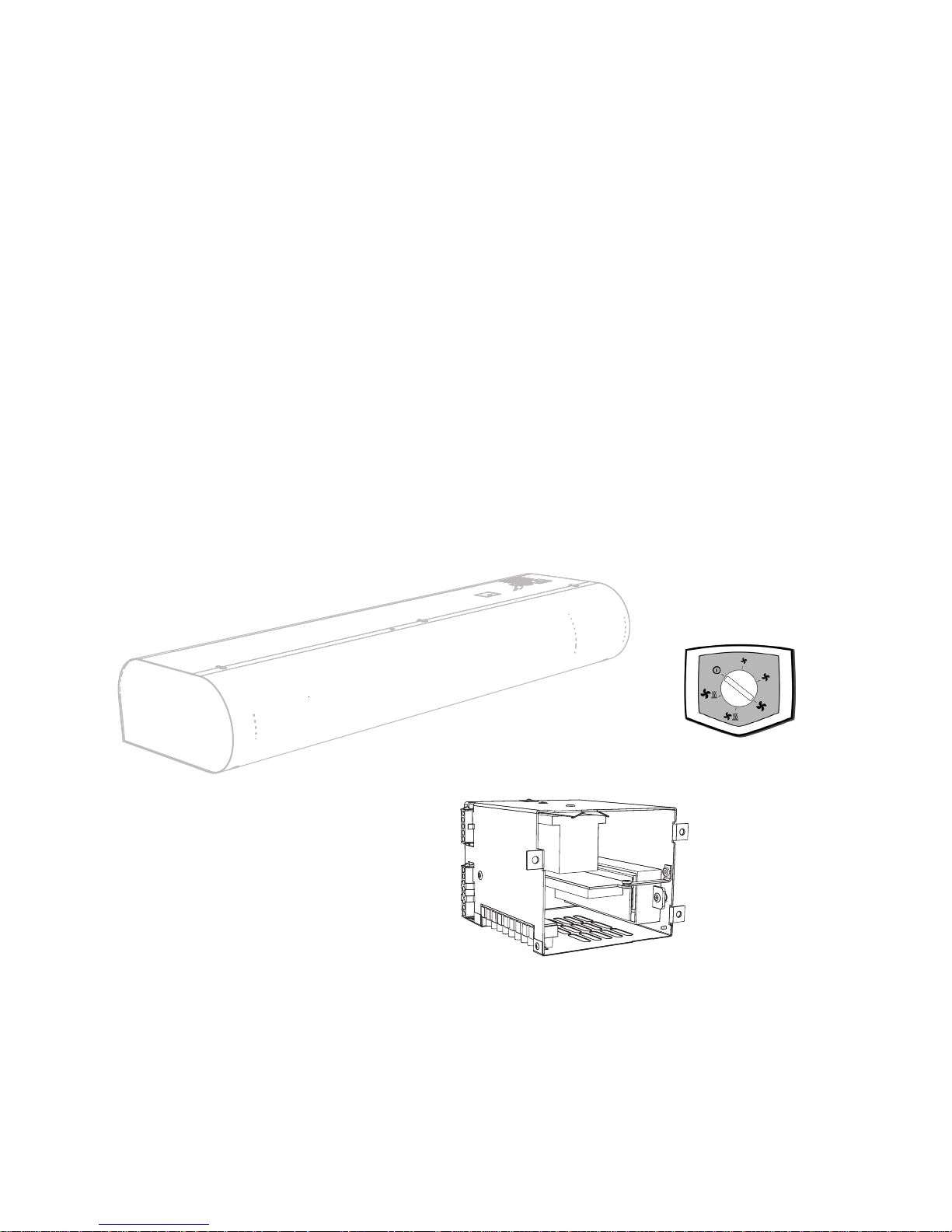
4.7. Install the bottom cover
1. slide the cover into the grooves (see picture below - direction 1)
2. pull the cover towards the unit (see picture below - direction 2)
3. screw the bottom cover to the unit
ATTENTION!
Before putting the air curtain into operation check:
• Whether any tools or other items that could damage the air
curtain have been left in the air curtain.
• Whether the electrical power supply is properly connected
and whether the heating water connection is properly connected.
• Whether the all the covers are properly attached.
• Whether the control panel is correctly connected.
By turning on for the rst time test that the device is in order
(the fans run, heating). Check other possible settings and product functions according to the individual regulation module
user‘s manuals.
6. INSTALLATION
7. SWITCHING
ON FOR THE FIRST TIME
REGULATION AND ACCESSORIES
It is possible to connect the following regulation modules to
ESSENSSE air curtains:
Regulation
type
Type
of
curtain
DK-1
SH-
-TM848
TER-P ZV-3 DS TV1/1
Regulation
code
DM
cold X X - - X - RGJ-VCE-DM-S
water X X X X X X RGJ-VCE-DM-V
electric X X X - X - RGJ-VCE-DM-E
RF
cold - - - - X - RGJ-VCE-RF-VS
water - - - - X X RGJ-VCE-RF-VS
electric - - X - X - RGJ-VCE-RF-E
x ... can be connected
- ... cannot be connected
You will nd a detailed description of the accessories in the
manuals of the individual regulation modules.
7.1 SETTING THE DIRECTION OF THE AIR
EXHAUST
ATTENTION!
Perform the setting during the installation of the curtain by
deviating the exhaust to the required direction. The Essensse air curtain makes it possible to turn the air exhaust at the
maximum angle of 15°.The exhaust direction setting is not
designed to be moved frequently.
1
2
14
9. CONCLUSION
After installing the air curtain, carefully read the Manual for the respective regulation module. If anything is unclear or you have
questions, do not hesitate to contact our sales or technical support department.
CONTACT
Adress:
Onninen Oy
Mittalinja 1
01260 Vantaa
Finland
Internet:
www.onninen.
9. CONCLUSION
8. MAINTENANCE AND CLEANING
ATTENTION!
Before carrying out any work inside the air curtain, the main power input must be disconnected. The air curtain must be
allowed to cool down!
• It is forbidden to use compressed air, aggressive chemicals, solvents or water for cleaning.
• Clean using a damp cloth, ne brush or vacuum cleaner.
• Clean the surface of the air curtain including the suction inlet part.
• Clean as necessary, it is recommended that cleaning should be performed at least once every 3 months.
• Adhere to workplace safety and use protective aids.

15

16
17
SM MODULE
INSTALLATION
,
OPERATION AND HANDLING
18
4.1 SM REGULATION DIAGRAM
4. INSTALLATION
RGJ-VCE-SM-E
LM1M2M3E1E2 Th Th DS DS L1 L2 L2 N Pe
L1 L2 L2 NPe
5
4
3
2
1
8
7
6
5
4
3
2
1
f
e
dcb
a
65432
1
L
S
M1M2M3
E1
E2
0 12345
a - 1
b - 2
c - 3
d - 4
e - 5
f - 6
x
xx
x
xx
x
x
xx
x
x
DS
19
4. INSTALLATION
RGJ-VCE-SM-VS
LM1M2M3
DS DS
L
L
N
N
Pe
Pe
5
4
3
2
1
a
c
d
f
134
6
L
S
M1M2M3
III III IV
a - 1
c - 3
d - 4
f - 6
x
x
x
x
x
x
DS
20
4.2 CONTROL PANEL
5. EXTERNAL ACCESSORIES
5.1 CONNECTING EXTERNAL ACCESSORIES
DO NOT MISS!
• When connecting external accessories, the air curtain must be disconnected from mains el. power.
• All external control components must be connected according to the electrical diagram.
• Connectors must connected to the electrical board with appropriate force and always perpendicular to the base.
5.1-1 DS Door switch
TECHNICAL INFORMATION
- Suitable for all SM regulations
- Insulated switching contact with a max. voltage of 230V, 6A
- IP67, can be connected as a switching or break contact
Connectors on SM control modules: DS / DS
ATTENTION!
Not supplied with the product.
5.1-2 Thermostatic valve – TV1/1
TECHNICAL INFORMATION
- Thermostatic valve for regulation of the water heat exchanger
- Suitable for all curtain models with a water heat exchanger
-Works independently of the control electronics
ATTENTION!
Not supplied with the product.
4. INSTALLATION
 Loading...