

PROFESSIONAL
Side 1Norwegian
TRMS IP67 Digital multimeter | 920
PROFESSIONAL
English
Finnish
Norwegian
Swedish
920
10
20
30
40
50
60
0
TRUE RMS IP67 MULTIMETER
V
V
V
mA
A
Side 2 English
Introduction
This meter measures AC/DC Voltage, AC/DC Current, Resistance,
Capacitance, Frequency (electrical & electronic), Diode Test, and
Continuity plus Thermocouple Temperature. Proper use and care of this
meter will provide many years of reliable service.
Safety
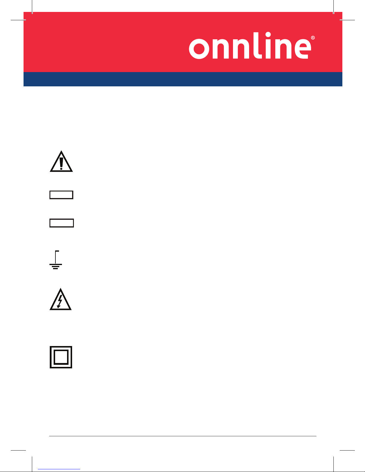
This symbol adjacent to another symbol, terminal or operating
device indicates that the operator must refer to an explanation in
the Operating Instructions to avoid personal injury or damage to
the meter.
This WARNING symbol indicates a potentially hazardous situation,
which if not avoided, could result in death or serious injury.
This CAUTION symbol indicates a potentially hazardous situation,
which if not avoided, may result damage to the product.
This symbol advises the user that the terminal(s) so marked
must not be connected to a circuit point at which the voltage with
respect to earth ground exceeds (in this case) 1000 VAC or VDC.
This symbol adjacent to one or more terminals identifies them
as being associated with ranges that may, in normal use, be
subjected to particularly hazardous voltages. For maximum safety,
the meter and its test leads should not be handled when these
terminals are energized.
This symbol indicates that a device is protected throughout by
double insulation or reinforced insulation.
WARNING
CAUTION
MAX
1000V

PROFESSIONAL
Side 3English
PER IEC1010 OVERVOLTAGE INSTALLATION CATEGORY
OVERVOLTAGE CATEGORY I
Equipment of OVERVOLTAGE CATEGORY I is equipment for connection to
circuits in which measures are taken to limit the transient overvoltages to
an appropriate low level.
Note – Examples include protected electronic circuits.
OVERVOLTAGE CATEGORY II
Equipment of OVERVOLTAGE CATEGORY II is energy-consuming equipment
to be supplied from the fixed installation.
Note – Examples include household, office, and laboratory appliances.
OVERVOLTAGE CATEGORY III
Equipment of OVERVOLTAGE CATEGORY III is equipment in fixed
installations.
Note – Examples include switches in the fixed installation and some
equipment for industrial use with permanent connection to the fixed
installation.
OVERVOLTAGE CATEGORY IV
Equipment of OVERVOLTAGE CATEGORY IV is for use at the origin of the
installation.
Note – Examples include electricity meters and primary over-current
protection equipment
Side 4 English
SAFETY INSTRUCTIONS
This meter has been designed for safe use, but must be operated with
caution. The rules listed below must be carefully followed for safe
operation.
1. NEVER apply voltage or current to the meter that exceeds the specified
maximum:
Input Protection Limits
Function Maximum Input
V DC or V AC 1000VDC/AC rms
mA AC/DC 800mA 1000V fast acting fuse
A AC/DC 10A 1000V fast acting fuse (20A for
30 seconds max every 15 minutes)
Frequency, Resistance,
Capacitance, Duty Cycle, Diode
Test, Continuity
1000VDC/AC rms
Temperature 1000VDC/AC rms
2. USE EXTREME CAUTION when working with high voltages.
3. DO NOT measure voltage if the voltage on the “COM” input jack exceeds
1000V above earth ground.
4. NEVER connect the meter leads across a voltage source while the
function switch is in the current, resistance, or diode mode. Doing so
can damage the meter.
5. ALWAYS discharge filter capacitors in power supplies and disconnect
the power when making resistance or diode tests.
6. ALWAYS turn off the power and disconnect the test leads before opening
the covers to replace the fuse or batteries.
7. NEVER operate the meter unless the back cover and the battery and
fuse covers are in place and fastened securely.
If the equipment is used in a manner not specified by the manufacturer,
the protection provided by the equipment may be impaired.
PROFESSIONAL
Side 5English
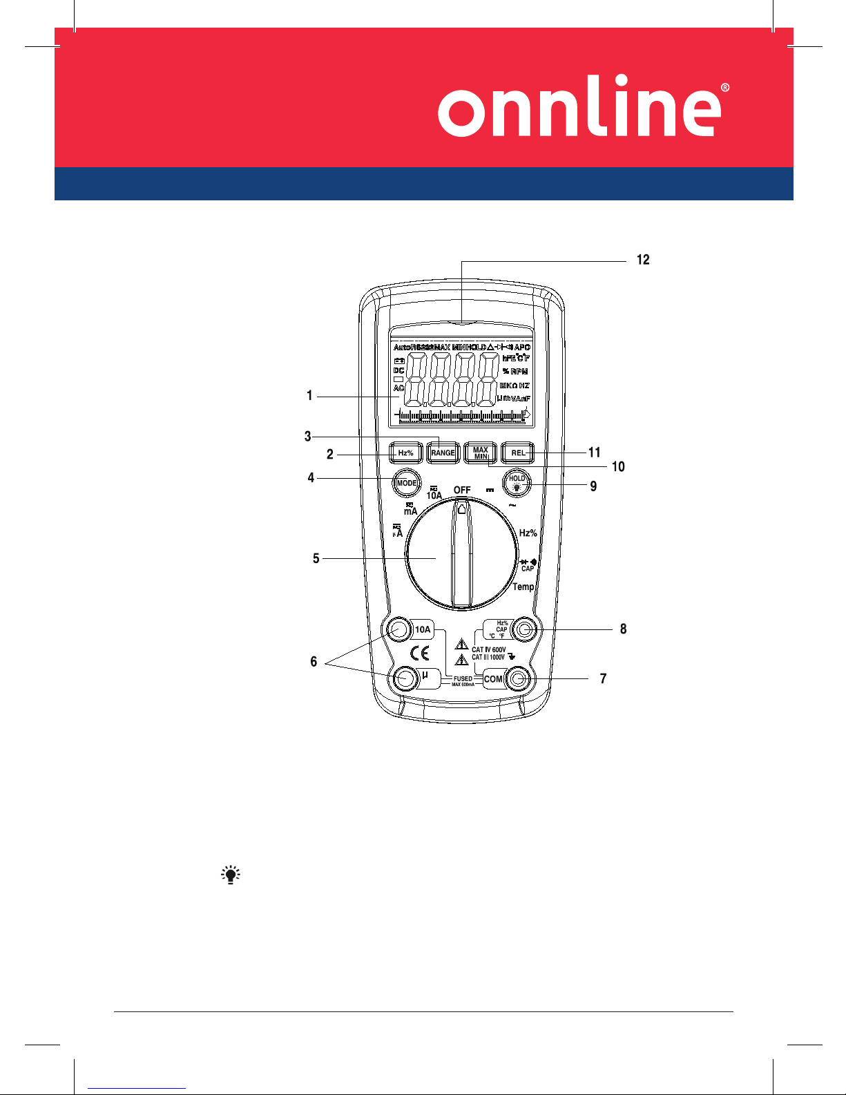
Controls and Jacks
1. 6,000 count LCD display
2. Hz% button
3. RANGE button
4. MODE button
5. Function switch
6. mA, µA and 10A input jacks
7. COM input jack
8. Positive input jack
9. Backlight
and Hold button
10. MAX/MIN button
11. REL button
12. NCV indicate lamp
Note: Tilt stand and battery compartment are on rear of unit.
¦ ¸
mA
A
¦ ¸
V
V
V
1
4
P1
P2
P3
S1
S2
BP0
BP60
BP1
Side 6 English
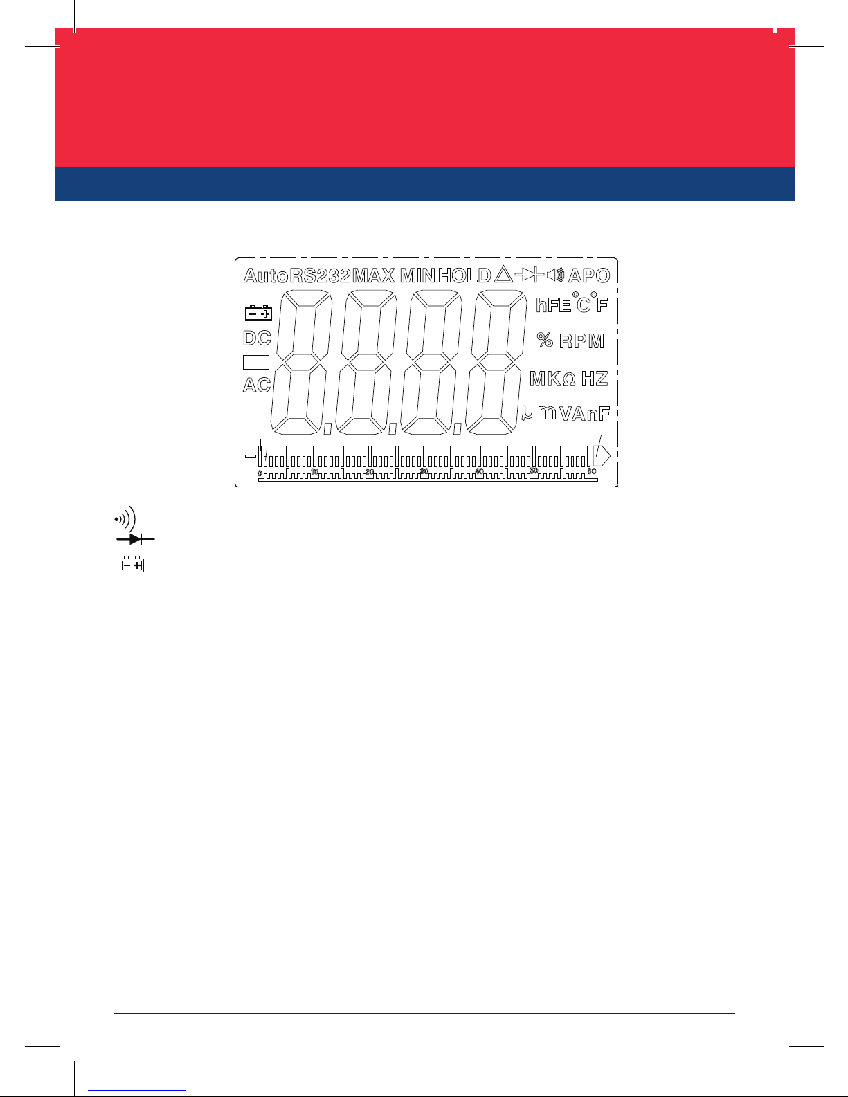
Symbols and Annunciators
Continuity
Diode test
Battery status
n nano (10-9) (capacitance)
µ micro (10-6) (amps, cap)
m milli (10-3) (volts, amps)
A Amps
k kilo (103) (ohms)
F Farads (capacitance)
M mega (106) (ohms)
Ω Ohms
Hz Hertz (frequency) V Volts
REL Relative
AC Alternating current AUTO Autoranging
DC Direct current HOLD Display hold
ºF Degrees Fahrenheit ºC Degrees Centigrade
MAX Maximum MIN Minimum
AUTO Auto Range
APO Auto OFF
Backlight
BP1 Bargraph
1
4
P1
P2
P3
S1
S2
BP0
BP60
BP1
PROFESSIONAL
Side 7English
Operating Instructions
1. ALWAYS turn the function switch to the OFF position when the meter is
not in use.
2. If “OL” appears in the display during a measurement, the value exceeds
the range you have selected. Change to a higher range.
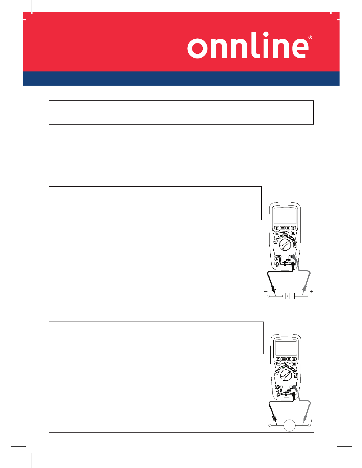
DC VOLTAGE MEASUREMENTS
1. Set the function switch to the “DC” position.
2. Insert the black test lead banana plug into the negative
COM jack. Insert the red test lead banana plug into the
positive V jack.
3. Touch the black test probe tip to the negative side of the
circuit. Touch the red test probe tip to the positive side
of the circuit.
4. Read the voltage in the display.
AC VOLTAGE MEASUREMENTS
1. Set the function switch to “AC” position.
2. Insert the black test lead banana plug into the negative
COM jack. Insert red test lead banana plug into the positive
V jack.
3. Touch the black test probe tip to the neutral side of the
circuit. Touch the red test probe tip to the “hot” side of the
circuit.
4. Read the voltage in the display
WARNING: Risk of electrocution. High-voltage circuits, both AC and DC,
are very dangerous and should be measured with great care.
CAUTION: Do not measure DC voltages if a motor on the
circuit is being switched ON or OFF. Large voltage surges
may occur that can damage the meter.
CAUTION: Do not measure AC voltages if a motor on the
circuit is being switched ON or OFF. Large voltage surges
may occur that can damage the meter.
G~

Side 8 English
AC/DC CURRENT MEASUREMENTS
1. Insert the black test lead banana plug into the negative COM
jack.
2. For current measurements up to 6000µA AC/DC, set the
function switch to the µA position and insert the red test lead
banana plug into the µA/mA jack,press mode button to select
AC or DC.
3. For current measurements up to 600mA DC, set the function
switch to the mA position and insert the red test lead banana
plug into the µA/mA jack ,press mode button to select AC or
DC.
4. For current measurements up to 10A DC, set the function
switch to the 10A position and insert the red test lead banana
plug into the 10A jack, press mode button to select AC or DC.
5. Remove power from the circuit under test, then open up the
circuit at the point where you wish to measure current.
6. Touch the black test probe tip to the negative side of the circuit. Touch the red
test probe tip to the positive side of the circuit.
7. Apply power to the circuit and read the current in the display.
RESISTANCE MEASUREMENTS
1. Set the function switch to the Ω CAP
position.
2. Insert the black test lead banana plug into the negative
COM jack. Insert the red test lead banana plug into the
positive V jack.
3. Press the MODE button to indicate “Ω” on the display.
4. Touch the test probe tips across the circuit or part under test.
It is best to disconnect one side of the part under test so
the rest of the circuit will not interfere with the resistance
reading.
CAUTION: Do not make 10A current measurements for longer than 30
seconds. Exceeding 30 seconds may cause damage to the meter and/or the
test leads.
WARNING: To avoid electric shock, disconnect power to the
unit under test and discharge all capacitors before taking
any resistance measurements. Remove the batteries and
unplug the line cords.
PROFESSIONAL
Side 9English
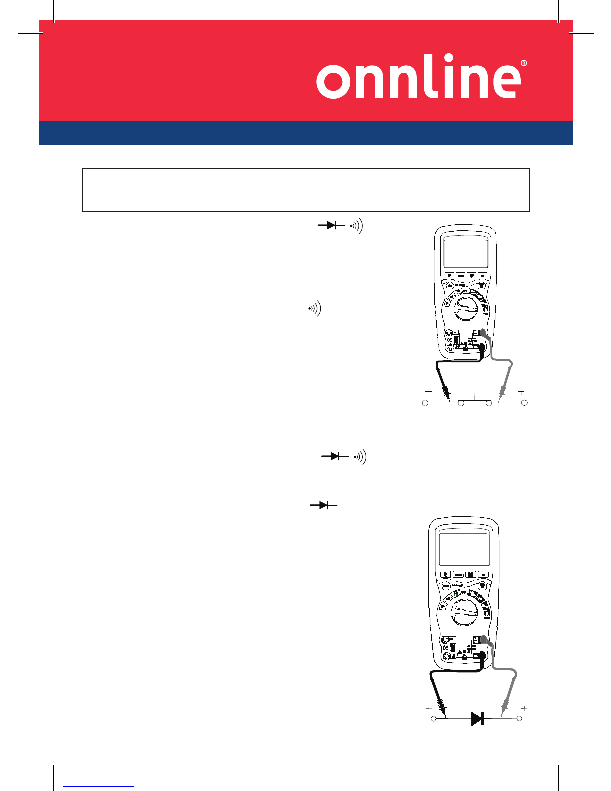
CONTINUITY CHECK
1. Set the function switch to the Ω CAP
position.
2. Insert the black lead banana plug into the negative
COM jack. Insert the red test lead banana plug into
the positive V jack.
3. Press the MODE button to indicate“
“ and “Ω” on
the display
4. Touch the test probe tips to the circuit or wire you
wish to check.
5. If the resistance is less than approximately 30Ω, the
audible signal will sound. If the circuit is open, the
display will indicate “OL”.
DIODE TEST
1. Set the function switch to the Ω CAP
position.
2. Insert the black test lead banana plug into the negative COM jack and
the red test lead banana plug into the positive V jack.
3. Press the MODE button to indicate“ “ and “V” on the display.
4. Touch the test probes to the diode under test.
Forward voltage will typically indicate 0.400 to
0.700V. Reverse voltage will indicate “OL”.
Shorted devices will indicate near 0V and an
open device will indicate “OL” in both
polarities.
WARNING: To avoid electric shock, never measure continuity on circuits
or wires that have voltage on them.

Side 10 English
CAPACITANCE MEASUREMENTS
1. Set the rotary function switch to the Ω CAP
position.
2. Insert the black test lead banana plug into the COM jack.
3. Insert the red test lead banana plug into the V jack.
4. Touch the test leads to the capacitor to be tested. Read
the capacitance value in the display
TEMPERATURE MEASUREMENTS
1. Set the function switch to the “Temp” positive and press
the MODE key to select the “°C” measuring or “°F”
measuring.
2. Insert the Temperature Probe into the input jacks, making
sure to observe the correct polarity.
3. Touch the Temperature Probe head to the part
whose temperature you wish to measure. Keep the
probe touching the part under test until the reading
stabilizes (about 30 seconds).
4. Read the temperature in the display.
Note: The temperature probe is fitted with a type K
mini connector. A mini connector to banana connector
adaptor is supplied for connection to the input banana
jacks.
FREQUENCY MEASUREMENT
1. Set the function switch to the Hz/Duty position.
2. Insert the black test lead banana plug into the negative ( - ) jack (COM) and
the red test lead banana plug into the positive ( + ) jack (°F).
3. Touch the test probe tips to the circuit under test.
4. Read the frequency in the display. The digital reading will indicate the
proper decimal point, symbols (Hz, kHz, MHz ) and value.
NOTE: Press the MODE key to select the frequency or the duty cycle
measuring.
WARNING: To avoid electric shock, disconnect power to the unit under test
and discharge all capacitors before taking any capacitance measurements.
Remove the batteries and unplug the line cords.

PROFESSIONAL
Side 11English
NCV-contact AC Voltage Test (NCV)
1. Set the function switch to the ON position.
2. Remove the meter and face the NCV detector to ACV source.
3. If source votalge above 110V ,the NCV indicate lamp will light.
MODE BUTTON
1. To select DC/AC current or voltage or resistance/capacitance Diode/
Continuity or °C /°F or Hz/duty
2. Press the key then turn on the power , the Auto Power-off function
will be cancelled, the sign “APO” disappears in the LCD; and enters into
the sleep status (power-off), press the key then power on will have Auto
Power-off function.
DATA HOLD BUTTON
The Data Hold function allows the meter to “freeze” a measurement for
later reference.
1. Press the DATA HOLD button to “freeze” the reading on the indicator.
The indicator “HOLD” will be appear in the display.
2. Press the DATA HOLD button to return to normal operation.
3. Press the DATA HOLD button to last 2 second, the back light function is
enabled or disenabled.
RANGE BUTTON
When the meter is first turned on, it automatically goes into AutoRanging.
This automatically selects the best range for the measurements being
made and is generally the best mode for most measurements. For
measurement situations requiring that a range be manually selected,
perform the following:
1. Press the RANGE button. The “AUTO” display indicator will turn off.
2. Press the RANGE button to step through the available ranges until you
select the range you want.
3. Press and hold the RANGE button for 2 seconds to exit the Manual
Ranging mode and return to Auto Ranging.
Side 12 English
MAX/MIN BUTTON
The meter displays the maximum or minimum value of input in the Max/
Min mode. When Max/Min is pressed for the first time, the meter displays
the maximum value. The meter displays the minimum value when it is
pressed again. When Max/Min is pressed for the third time, the meter
displays current value. The meter returns to normal operation when Max/
Min is pressed and held for longer than one second. Press HOLD key
in Max/Min mode makes the meter stop updating the maximum or the
minimum value.
Low battery indication
When the icon appears alone in the display, the battery should be
replaced.
Maintenance
This MultiMeter is designed to provide years of dependable service, if the
following care instructions are performed:
1. KEEP THE METER DRY. If it gets wet, wipe it off.
2. USE AND STORE THE METER IN NORMAL TEMPERATURES.
Temperature extremes can shorten the life of the electronic parts and
distort or melt plastic parts.
3. HANDLE THE METER GENTLY AND CAREFULLY. Dropping it can damage
the electronic parts or the case.
4. KEEP THE METER CLEAN. Wipe the case occasionally with a damp cloth.
DO NOT use chemicals, cleaning solvents, or detergents.
5. USE ONLY FRESH BATTERIES OF THE RECOMMENDED SIZE AND TYPE.
Remove old or weak batteries so they do not leak and damage the unit.
6. IF THE METER IS TO BE STORED FOR A LONG PERIOD OF TIME, the
batteries should be removed to prevent damage to the unit.
WARNING: To avoid electric shock, disconnect the test leads from any
source of voltage before removing the back cover or the battery or fuse
covers.
WARNING: To avoid electric shock, do not operate your meter until the
battery and fuse covers are in place and fastened securely.
PROFESSIONAL
Side 13English
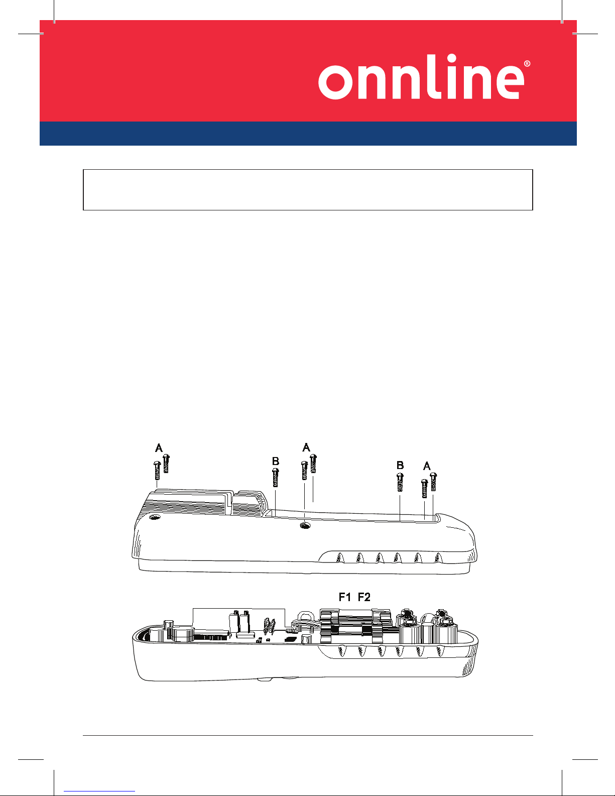
BATTERY INSTALLATION
1. Turn power off and disconnect the test leads from the meter.
2. Open the rear battery cover by removing two screws (B) using a Phillips
head screwdriver.
3. Insert the battery into battery holder, observing the correct polarity.
4. Put the battery cover back in place. Secure with the screws.
WARNING: To avoid electric shock, do not operate the meter until the
battery cover is in place and fastened securely.
NOTE: If your meter does not work properly, check the fuses and batteries
to make sure that they are still good and that they are properly inserted.
WARNING: To avoid electric shock, disconnect the test leads from any
source of voltage before removing the battery cover.
Side 14 English
Specifications
DC Voltage (Auto-ranging)
Range Resolution Accuracy
600.0mV 0.1mV
±0.1% of rdg ±2 digits
6.000V 1mV
60.00V 10mV
600.0V 100mV
1000V 1V ±0.3% of rdg ±2 digits
Input Impedance: 10MΩ.
Maximum Input: 1000V dc or 1000V ac rms.
AC Voltage (Auto-ranging)
Range Resolution Accuracy
6.000V 1mV
±0.8% of rdg ±4 digits60.00V 10mV
600.0V 100mV
1000V 1V ±1.2% of rdg ±4 digits
All AC voltage ranges are specified from 5% of range to 100% of range
Input Impedance: 10MΩ.
AC Response: 50 Hz to 400Hz
Maximum Input: 1000V dc or 1000V ac rms.
DC Current (Auto-ranging)
Range Resolution Accuracy
600.0uA 0.1uA
±0.8% of rdg ±3 digits6000uA 1uA
60.00mA 10uA
600.0mA 100uA ±1.2% of rdg ±3 digits
10A 10mA ±1.8% of rdg ±3 digits
Overload Protection: FF800mA / 1000V and F10A / 1000V Fuse.
Maximum Input: 6000uA dc on uA range
800mA dc on mA range
10A dc on 10A range.

PROFESSIONAL
Side 15English
AC Current (Auto-ranging)
Range Resolution Accuracy
600.0uA 0.1uA
±1.0% of rdg ±3 digits6000uA 1uA
60.00mA 10uA
600.0mA 100uA ±1.2% of rdg ±3 digits
10A 10mA ±2.0% of rdg ±3 digits
All AC Current ranges are specified from 5% of range to 100% of range
Overload Protection:FF800mA/1000V and F10A/1000V Fuse.
AC Response: 50 Hz to 400 Hz
Maximum Input: 6000uA ac rms on uA
800mA ac rms on mA
10A ac rms on 10A range.
Resistance [Ω] (Auto-ranging)
Range Resolution Accuracy
600.0Ω 0.1Ω ±0.5% of rdg ±4 digits
6.000kΩ 1Ω
±0.5% of rdg ±2 digits60.00kΩ 10Ω
600.0kΩ 100Ω
6.000MΩ 1kΩ
±1.5% of rdg ±8 digits
60.00MΩ 10kΩ
Input Protection: 1000V dc or 1000V ac rms.
Capacitance (Auto-ranging)
Range Resolution Accuracy
40.00nF 10pF ±5.0% of rdg ±20 digits
400.0nF 0.1nF
±3.0% of rdg ±5 digits
4.000uF 1nF
40.00uF 10nF
400.0uF 0.1uF
4000uF 1 uF ±5.0% of rdg ±10 digits
Input Protection: 1000V dc or 1000V ac rms.

Side 16 English
Frequency (Auto-ranging)
Range Resolution Accuracy
9.999Hz 0.001Hz
±1.2% of rdg ±3 digits
99.99 Hz 0.01Hz
999.9 Hz 0.1Hz
9.999KHz 1 Hz
99.99kHz 10Hz
999.9kHz 100Hz
9.999MHz 1kHz ±1.5% of rdg ±4 digits
Sensitivity: >0.5V RMS while ≤1MHz ;
Sensitivity: >3V RMS while >1MHz ;
Input Protection: 1000V dc or 1000V ac rms.
Duty Cycle
Range Resolution Accuracy
0.1%~99.9% 0.1% ±1.2% of rdg ±2 digits
Pulse width: >100us, <100ms;
Frequency width: 5Hz – 150kHz
Sensitivity: <0.5V RMS
Overload protection: 1000V dc or ac rms.
Temperature
Range Resolution Accuracy
-20°C ~+600°C 0.1 °C
± 3% of rdg ± 5 °C
600°C ~+1000°C 1 °C
-4 °F ~+600 °F 0.1°F
± 3% of rdg ± 8 °F
600°F ~+1832 °F 1°F
Sensor: Type K Thermocouple
Overload protection: 1000V dc or ac rms.
PROFESSIONAL
Side 17English
Diode Test
Range Resolution Accuracy
0.3mA typical 1 mV ±10% of rdg ±5 digits
Open circuit voltage: MAX. 2V dc
Overload protection: 1000V dc or ac rms.
Audible continuity
Audible threshold: Less than 30Ω Test current MAX. 0.3mA
Overload protection: 1000V dc or ac rms.
Enclosure Double molded, waterproof
Shock (Drop Test) 6.5 feet (2 meters)
Diode Test Test current of 0.9mA maximum, open circuit
voltage 2V DC typical
Continuity Check Audible signal will sound if the resistance is
less than 30Ω (approx.), test current <0.3mA
Temperature Sensor Requires type K thermocouple
Input Impedance >10MΩ VDC & >9MΩ VAC
AC Response True rms
AC True RMS: The term stands for “Root-Mean-Square,”
which represents the method of calculation
of the voltage or current value. Average
responding multimeters are calibrated to read
correctly only on sine waves and they will read
inaccurately on non-sine wave or distorted
signals. True rms meters read accurately on
either type of signal.
ACV Bandwidth 50Hz to 400Hz
Crest Factor ≤3 at full scale up to 500V, decreasing linearly
to ≤1.5 at 1000V
Display 60,00 count backlit liquid crystal with
bargraph
Overrange indication “OL” is displayed
Auto Power Off 15 minutes (approximately) with disable
feature

Side 18 English
Polarity Automatic (no indication for positive); Minus
(-) sign for negative
Measurement Rate 2 times per second, nominal
Low Battery Indication “ ” is displayed if battery voltage drops
below operating voltage
Battery One 9 volt (NEDA 1604) battery
Fuses mA, µA ranges; 0.8A/1000V ceramic fast blow
A range; 10A/1000V ceramic fast blow
Operating Temperature 41ºF to 104ºF (5ºC to 40ºC)
Storage Temperature -4°F to 140°F (-20°C to 60°C)
Operating Humidity Max 80% up to 87ºF (31ºC) decreasing linearly
to 50% at 104ºF (40ºC)
Storage Humidity <80%
Operating Altitude 7000ft. (2000meters) maximum.
Weight 0.753lb (342g) (includes holster).
Size 7.36” x 3.2” x 2.0” (187 x 81 x 50mm) (includes
holster)
Safety This meter is intended for origin of installation
use and protected, against the users, by
double insulation per EN61010-1 and
IEC61010-1 2nd Edition (2001) to Category IV
600V and Category III 1000V; Pollution Degree
2. The meter also meets UL 61010-1, 2nd
Edition (2004), CAN/CSA C22.2 No. 61010-1
2nd Edition (2004), and UL 61010B-2-031, 1st
Edition (2003).
PROFESSIONAL
Side 19Finnish
Johdanto
Tällä yleismittarilla voi testata AC/DC-jännitettä, AC/DC-virtaa,
resistanssia, kapasitanssia, frekvenssiä, diodeja, kontinuiteettia ja
lämpötilaa. Oikein käytettynä ja hoidettuna laite toimii luotettavasti vuosia.
Turvallisuus
Tämä symboli toisen symbolin, terminaalin tai käyttöyksikön
vieressä osoittaa, että käyttäjän on luettava selitys käyttöohjeesta
välttyäkseen henkilö- tai laitevahingolta.
Tämä varoitusmerkki osoittaa mahdollista vaaratilannetta, joka voi
johtaa vakavaan vammaan tai kuolemaan
Tämä varoitusmerkki osoittaa mahdollista vaaratilannetta, joka voi
aiheuttaa laitteen vaurioitumisen.
Tämä merkintä muistuttaa käyttäjää siitä, että merkitty/merkityt
terminaali/t eivät saa olla yhdistettyinä piiriin, jossa jännite
suhteessa maahan ylittää (tässä tapauksessa) 1000 VAC tai VDC.
Tällä merkinnällä yhden tai useiden terminaalien vieressä
tarkoitetaan alueita, jotka normaalikäytössä voivat altistua
erityisen vaarallisille jännitteille. Turvallisuuden takaamiseksi
laitetta ja testijohtoa ei saa käsitellä kun näissä terminaaleissa on
jännitettä.
Tämä merkintä kertoo, että laite on suojattu kaksinkertaisella tai
vahvistetulla eristyksellä.
VAROITUS
VA RO
MAX
1000V

Side 20 Finnish
IEC1010-ylijänniteluokat:
YLIJÄNNITELUOKKA I
YLIJÄNNITELUOKKA I:een kuuluvat piireihin kytkettävät laitteet,
joissa ohimenevät ylijännitteet on rajoitettu sopivan matalalle tasolle.
Esimerkkeinä suojatut elektroniset piirit.
YLIJÄNNITELUOKKA II
YLIJÄNNITELUOKKA II:een kuuluvat energiaa kuluttavat, kiinteän
asennuksen laitteet. Esimerkkeinä kotitalous-, konttori- ja
laboratoriolaitteet.
YLIJÄNNITELUOKKA III
YLIJÄNNITELUOKKA III:een kuuluvat pysyvästi asennetut laitteet.
Esimerkkeinä kiinteiden asennusten katkaisijat sekä laitteet, jotka ovat
kiinni kiinteässä asennuksessa.
YLIJÄNNITELUOKKA IV
YLIJÄNNITELUOKKA IV:een kuuluvat laitteet on tarkoitettu sähkön
syöttöpisteisiin/jakeluun. Esimerkkeinä sähkömittarit ja sähköverkon
valvontalaitteet.

PROFESSIONAL
Side 21Finnish
Turvallisuus:
Tämä laite on suunniteltu niin, että sen käyttö on turvallista. Siitä
huolimatta käytössä on noudatettava turvatoimia. Turvallinen käyttö
edellyttää seuraavien ohjeiden noudattamista.
1. Mittarin jännite tai virta ei saa ylittää seuraavia ohjearvoja:
Sisääntulon suojarajat
Toiminto Enimmäissyöttö
V DC tai V AC 1000VDC/AC rms
mA AC/DC 800mA 1000V pikasulake
A AC/DC 10A 1000V pikasulake (20A 30
sekuntia enintään 15 minuutin
välein)
Frekvenssi, resistanssi,
kapasitanssi, Duty Cycle, diodin
testaus, kontinuiteetti
1000VDC/AC rms
Lämpötila 1000VDC/AC rms
2. Työskentele varoen suurjännitteiden kanssa!
3. Älä mittaa jännitettä, jos se ylittää 1000V maata kohti ”COM”sisääntulossa.
4. Älä KOSKAAN yhdistä mittausjohtoja jännitelähteeseen, kun
valintakytkin on virta-, vastus- tai dioditestausasennossa. Muutoin laite
voi vaurioitua.
5. Päästä jännite aina kondensaattoriin ennen resistanssimittausta tai
dioditestausta.
6. Ennen kuin avaat laitteen sulakkeen tai akun vaihtoa varten, kytke
laitteesta aina virta pois ja poista mittajohdot.
7. Älä koskaan käytä laitetta, jos se on avattu tai jos sen kansi ei ole
kunnolla kiinni.
Jos laitetta käytetään muuhun kuin valmistajan nimeämään tarkoituksen,
sen turvallisuutta ei voida taata.

Side 22 Finnish
Toimintapainikkeet ja liittimet
1. 6000 numeron LCD-näyttö
2. Hz%-painike
3. RANGE-painike
4. MODE-painike
5. Valintakytkin
6. mA-, µA- ja 10A-sisääntuloterminaali
7. COM-sisääntuloterminaali
8. Positiivinen sisääntuloterminaali.
9. Taustavalo ja Hold-painike
10. MAX/MIN-painike
11. REL-painike
12. NCV - kosketuksettoman jännitteen ilmaisin
HUOM: Tuki ja akkulokero laitteen takana.
¦ ¸
mA
A
¦ ¸
V
V
V
1
4
P1
P2
P3
S1
S2
BP0
BP60
BP1

PROFESSIONAL
Side 23Finnish
Symbolit ja varoitustestit
Kontinuiteetti
Dioditesti
Akun varaustila
n nano (10-9) (kapasitanssi)
µ micro (10-6) (amppeeri, kap)
m micro (10
-3
) (voltti, amppeeri)
A Amppeeri
k kilo (10
3
) (ohmi)
F Faradi (Kapasitanssi)
M mega (106) (ohmi)
Ω Ohmi
Hz Hertsi (frekvenssi)
V Voltti
REL Suhteellinen
AC Vaihtovirta AUTO Automaattialue
DC Tasavirta HOLD Näytön pysäytys
ºF Lämpötila (Fahrenheit) ºC Lämpötila (Celsius)
MAX Maksimi MIN Minimi
Aikasymboli
BP1 Pylväsdiagrammi
1
4
P1
P2
P3
S1
S2
BP0
BP60
BP1

Side 24 Finnish
Käyttöohjeet
1. Pidä valintakytkin OFF-asennossa, kun mittaria ei käytetä.
2. Kun näytössä näkyy ”OL” mittauksen aikana, arvo ylittää valitun alueen.
Vaihda alue suuremmaksi.
DC-JÄNNITTEEN MITTAUS
1. Käännä valintakytkin DC-asentoon.
2. Liitä musta mittajohto negatiiviseen (-) COM-terminaaliin.
Liitä punainen mittajohto positiiviseen (+) V-terminaaliin.
3. Pidä mustaa mittakärkeä piirin negatiivista puolta vasten.
Pidä punaista mittakärkeä piirin positiivista puolta vasten.
4. Lue jännite näytöltä.
AC-JÄNNITTEEN MITTAUS
1. Käännä valintakytkin AC-asentoon.
2. Liitä musta mittajohto COM-terminaaliin.
Liitä punainen mittajohto V-terminaaliin.
3. Pidä mustaa mittakärkeä piirin negatiivista puolta vasten.
Pidä punaista mittakärkeä piirin positiivista puolta vasten.
4. Lue jännite näytöltä.
VAROITUS: Sähköiskuvaara. AC- ja DC-suurjännitepiirit ovat erittäin
vaarallisia ja niiden mittauksessa on noudatettava suurta varovaisuutta.
VARO: Älä mittaa DC-jännitettä, jos piirissä oleva moottori
käynnistetään tai sammutetaan. Ylijännite voi vahingoittaa
mittalaitetta.
VARO: Älä mittaa AC-jännitettä, jos piirissä oleva moottori
käynnistetään tai sammutetaan. Ylijännite voi vahingoittaa
mittalaitetta.
G~

PROFESSIONAL
Side 25Finnish
AC/DC-VIRRAN MITTAUS
1. Liitä musta mittausjohto negatiiviseen COM-sisääntuloon.
2. Kun mittaat enintään 6000µA AC/DC virtaa, käännä
valintakytkin µA-asentoon ja liitä punainen mittausjohto µA/
mA-sisääntuloon, paina mode-painiketta valitaksesi AC:n tai
DC:n.
3. Kun mittaat enintään 600mA AC/DC virtaa, käännä
valintakytkin mA-asentoon ja liitä punainen mittausjohto µA/
mA-sisääntuloon. Paina mode-painiketta valitaksesi AC tai
DC.
4. Kun mittaat enintään 10A DC virtaa, käännä valintakytkin
10A-asentoon ja liitä punainen mittausjohto 10A-sisääntuloon,
paina mode-painiketta valitaksesi AC:n tai DC:n.
5. Kytke virta pois testattavasta piiristä ja avaa piiri
mittauspaikasta.
6. Pidä mustaa mittakärkeä piirin negatiivista puolta vasten.
Pidä punaista mittakärkeä piirin positiivista puolta vasten.
7. Lue virran arvo näytöltä.
RESISTANSSIN MITTAUS
1. Aseta valintakytkin asentoon Ω CAP
.
2. Liitä musta mittajohto COM-terminaaliin.
Liitä punainen mittajohto Ω-terminaaliin.
3. Paina Mode-painiketta, jolloin “Ω” näkyvät näytöllä.
4. Aseta mittausjohtojen kärjet rinnakkain mitattavan
vastuksen kanssa, ja kytke pois mahdolliset muut piirit
mittaushäiriöiden varalta.
5. Lue tulos näytöltä.
VARO: 10A-mittaukset eivät saa kestää 30 sekuntia pidempään. Muutoin laite
tai testausjohdot voivat vaurioitua.
VARO: Sähköiskun välttämiseksi kytke virta pois laitteesta
testin ajaksi ja poista kaikki kondensaattorit ennen kuin teet
vastusmittauksia. Poista paristot ja irrota johdot.

Side 26 Finnish
KONTINUITEETIN TARKISTUS, ”SUMMING”
1. Aseta valintakytkin asentoon Ω CAP
.
2. Liitä musta mittajohto COM-terminaaliin.
Liitä punainen mittajohto V-terminaaliin.
3. Paina Mode-painiketta, jolloin“
“ ja “Ω” näkyvät
näytöllä.
4. Paina mittakärjet niitä kohtia vasten, josta haluat
tarkistaa liitännän.
5. Jos vastus on alle 30Ω, kuuluu äänimerkki. Jos piiri
on avoin, näytöllä on teksti ”OL”.
DIODITESTI
1. Aseta valintakytkin asentoon Ω CAP
.
2. Liitä musta mittajohto COM-terminaaliin. Liitä punainen mittajohto
V-terminaaliin.
3. Paina MODE-painiketta, jolloin “ “ ja “V” näkyvät näytöllä.
4. Aseta mittakärjet diodin päälle.
Johtojännite on tyypillisesti 0,400 - 0,700 V. Estosuunta
osoitetaan tekstillä ”OL”.
Oikosulussa diodi on lähes 0V ja diodin rikkoutuminen
näytetään tekstillä ”OL” kummassakin navassa.
VARO: Sähköiskun välttämiseksi kytke virta pois laitteesta testin ajaksi
ja poista kaikki kondensaattorit ennen kuin teet vastusmittauksia. Poista
paristot ja irrota johdot.

PROFESSIONAL
Side 27Finnish
KAPASITANSSIN MITTAUS
1. Aseta valintakytkin asentoon Ω CAP
.
2. Liitä musta mittajohto COM-terminaaliin.
3. Liitä punainen mittajohto V-terminaaliin.
4. Liitä mittakärjet mitattavaan kondensaattoriin.
Lue mittaustulos näytöltä.
LÄMPÖTILAN MITTAUS
1. Kierrä valintakytkin asentoon Temp ja valitse MODEpainikkeesta joko °C tai °F.
2. Liitä lämpötilan anturi terminaaleihin, muista oikea
napaisuus.
3. Paina lämpötilan anturi mitattavaa kohdetta vasten
kunnes näytössä oleva arvo vakiintuu (n. 30 sekuntia).
4. Lue lämpötila näytöltä.
HUOM: Lämpötila-anturissa on K-tyypin termopari.
Mukana banaaniliitintä varten on litteä puikko
terminaaleihin liittämistä varten.
FREKVENSSIN MITTAUS
1. Kierrä valintakytkin Hz/Duty-asentoon.
2. Liitä musta mittausjohto COM-terminaaliin ja
punainen mittajohto V-terminaaliin.
3. Liitä mittakärjet mitattavaan piiriin.
4. Lue mittaus näytöltä.
HUOM: Valitse MODE-painikkeella, käytätkö taajuus- vai Duty Cycle
-mittausta.
VARO: Sähköiskun välttämiseksi kytke virta pois laitteesta testin aksi ja poista
kaikki kondensaattorit ennen kuin teet vastus- tai kapasitanssimittauksia.

Side 28 Finnish
NCV - Kosketuksettoman jännitteen indikaattori
1. Käännä valintakytkin asentoon PÅ.
2. Pidä laitteen etuosaa ja NCV-anturia AC-jännitelähdettä kohti.
3. Jos jännite on yli 110V, näytön yllä oleva NCV-merkkivalo palaa
punaisena.
MODE-PAINIKE
1. Voit valita painikkeella DC/AC-virran, -jännitteen tai -resistanssin/
kapasitanssin, -diodin/-kontinuiteetin, Celsiuksen tai Fahrenheitin tai
Hz/Dutyn.
2. Pidä MODE-painiketta alas painettuna ja kytke laitteeseen siiten virta,
jolloin voit kytkeä pois automaattisen virrankatkaisutoiminnon (Auto
Power-off). Teksti APO häviää näytöltä. Laite siirtyy lepotilaan ”sleep
status” (power-off).
3. Pitämällä MODE-painiketta alaspainettuna ja käynnistämällä laitteen
automaattinen virrankatkaisutoiminta aktivoituu uudelleen.
DATA HOLD-PAINIKE
Painamalla Data Hold-painiketta mittausarvo jää näytölle.
1. Paina DATA HOLD-painiketta. Näytöllä näkyy sana HOLD.
2. Palaa normaalitilaan painamalla DATA HOLD-painiketta uudelleen.
3. Pidä DATA HOLD-painiketta alas painettuna vähintään 2 sekunnin ajan,
jolloin voit kytkeä taustavalon päälle tai pois.
RANGE-PAINIKE
Kun laite on kytketty päälle, se on automaattisesti tilassa, jossa se valitsee
mittausalueen automaattisesti. Laite valitsee itse parhaan mittausalueen,
ja tavallisesti se onkin paras useimpiin mittaustilanteisiin. Manuaalinen
mittaus tapahtuu seuraavasti:
1. Paina RANGE-painiketta. AUTO-teksti näytössä sammuu.
2. Paina RANGE-painiketta toistuvasti, jotta voisit valita sopivan
mittausalueen.
3. Paina RANGE-painiketta yhtämittaisesti vähintään 2 sekuntia, jolloin
alueen valinta palaa automaattiseksi.

PROFESSIONAL
Side 29Finnish
MAX/MIN-PAINIKE
Mittari osoittaa sisääntulevan datan korkeinta tai matalinta arvoa Max/
Min-asennossa. Kun Max/Min -painiketta painetaan ensimmäistä
kertaa, mittari näyttää maksimiarvon. Toisella painalluksella esiin tulee
alin arvo. Kun Max/Min –painiketta painetaan kolmatta kertaa, mittari
näyttää tämänhetkisen arvon. Laite palaa normaalikäyttöön, kun Max/
Min-painiketta pidetään alaspainettuna yli sekunti. Painamalla HOLDpainiketta Max/Min-tilassa mittari ei päivitä ylintä ja alinta arvoa.
VAROITUS PARISTOJEN TYHJENTYMISESTÄ
Kun näytössä näkyy pelkästään
ikoni, paristot on vaihdettava.
Huolto
Laite on suunniteltu ja rakennettu kestämään vuosia, kun noudatat
seuraavia ohjeita.
1. Säilytä laitetta kuivassa paikassa.
2. Käytä ja säilytä sitä normaalilämpötilassa.
3. Käsittele laitetta varoen ja vältä kovia iskuja ja kovaa käsittelyä.
4. Pidä laite ja johdot puhtaina. Puhdistus nihkeällä liinalla. Älä käytä
kemikaaleja tai liuottimia.
5. Käytä oikeita ja uusia paristoja.
6. Jos laitetta ei käytetä pitkään aikaan, poista paristot.
VARO: Sähköiskun välttämiseksi laite on irrotettava mittauspiiristä
ennen paristolokeron avaamista ja paristojen poistamista tai
sulakekannen avaamista.
VARO: Sähköiskun välttämiseksi laitetta ei saa käyttää ennen kuin
paristo ja sulakekansi ovat paikallaan ja kunnolla kiinni.

Side 30 Finnish
PARISTON ASENNUS
1. Kytke laitteesta virta pois ja poista mittausjohdot terminaaleista.
2. Avaa paristokansi (B) ruuvimeisselillä.
3. Vaihda uusi paristo; tarkista oikea napaisuus.
4. Aseta paristolokeron kansi paikoilleen ja ruuvaa ruuvit kiinni.
HUOM: Jos laite ei toimi kuten sen pitäisi, tarkista sulakkeet,
mittausjohdot ja paristot, että ne ovat hyvässä kunnossa ja hyvin
paikallaan.
VARO: Sähköiskun välttämiseksi laite on irrotettava mittauspiiristä
ennen paristokannen avaamista.

PROFESSIONAL
Side 31Finnish
Tekniset tiedot
DC-jännite (Automaattinen alue)
Alue Erottelukyky Tarkkuus
600.0mV 0.1mV
±0.1% lukemasta ±2 numeroa
6.000V 1mV
60.00V 10mV
600.0V 100mV
1000V 1V ±0.3% lukemasta ±2 numeroa
Sisääntuloimpedanssi: 10MΩ.
Maksimisisääntulo 1000V dc tai 1000V ac rms.
AC-jännite (Automaattinen alue)
Alue Erottelukyky Tarkkuus
6.000V 1mV
±0.8% lukemasta ±4 numeroa60.00V 10mV
600.0V 100mV
1000V 1V ±1.2% lukemasta ±4 numeroa
Kaikki AC-jännitealueet on eritelty 5 % - 100 % alueesta.
Sisääntuloimpedanssi: 10MΩ.
AC-vaste: 50 – 400 Hz
Maksimisisääntulo 1000V dc tai 1000V ac rms.
DC-virta (Automaattinen alue)
Alue Erottelukyky Tarkkuus
600.0uA 0.1uA
±0.8% lukemasta ±3 numeroa6000uA 1uA
60.00mA 10uA
600.0mA 100uA ±1.2% lukemasta ±3 numeroa
10A 10mA ±1.8% lukemasta ±3 numeroa
Sulake: F1 800mA / 1000V ja F2 10A / 1000V sulake.
Maksimisisääntulo 6000uA dc uA-alueella.
800mA dc mA-alueella.
10A dc 10A-alueella.

Side 32 Finnish
AC-virta (Automaattinen alue)
Alue Erottelukyky Tarkkuus
600.0uA 0.1uA
±1.0% lukemasta ±3 numeroa6000uA 1uA
60.00mA 10uA
600.0mA 100uA ±1.2% lukemasta ±3 numeroa
10A 10mA ±2.0% lukemasta ±3 numeroa
Kaikki AC-jännitealueet on eritelty 5 % - 100 % alueesta.
Sisääntuloimpedanssi: 10MΩ.
AC-vaste: 50 – 400 Hz
Maksimisisääntulo : 6000uA ac rms uA:lla
800mA ac rms mA:lla
10A ac 10A-alueella.
Resistanssi [Ω] (Auto-område)
Alue Erottelukyky Tarkkuus
600.0Ω 0.1Ω ±0.5% lukemasta ±4 numeroa
6.000kΩ 1Ω
±0.5% lukemasta ±2 numeroa60.00kΩ 10Ω
600.0kΩ 100Ω
6.000MΩ 1kΩ
±1.5% lukemasta ±8 numeroa
60.00MΩ 10kΩ
Sisääntulosuoja: 1000V dc tai 1000V ac rms.
Kapasitanssi (Automaattialue)
Alue Erottelukyky Tarkkuus
40.00nF 10pF ±5.0% lukemasta ±20 numeroa
400.0nF 0.1nF
±3.0% lukemasta ±5 numeroa
4.000uF 1nF
40.00uF 10nF
400.0uF 0.1uF
4000uF 1 uF ±5.0% lukemasta ±10 numeroa
Sisääntulosuoja: 1000V dc tai 1000V ac rms.

PROFESSIONAL
Side 33Finnish
Frekvenssi (Automaattialue)
Alue Erottelukyky Tarkkuus
9.999Hz 0.001Hz
±1.2% lukemasta ±3 numeroa
99.99 Hz 0.01Hz
999.9 Hz 0.1Hz
9.999KHz 1 Hz
99.99kHz 10Hz
999.9kHz 100Hz
9.999MHz 1kHz ±1.5% lukemasta ±4 numeroa
Herkkyys: >0.5V RMS ≤1MHz:llä;
Herkkyys: >3V RMS ≤1MHz:llä;
Sisääntulosuoja: 1000V dc tai 1000V ac rms.
Duty Cycle
Alue Erottelukyky Tarkkuus
0.1%~99.9% 0.1% ±1.2% lukemasta ±2 numeroa
Pulssileveys: >100us, <100ms;
Taajuusalue: 5Hz – 150kHz
Herkkyys: <0.5V RMS
Ylikuormitussuoja: 1000V dc tai ac rms.
Lämpötila
Alue Erottelukyky Tarkkuus
-20°C ~+600°C 0.1 °C
± 3% lukemasta ± 5 °C
600°C ~+1000°C 1 °C
-4 °F ~+600 °F 0.1°F
± 3% lukemasta ± 8 °F
600°F ~+1832 °F 1°F
Anturi: K-tyyppi
Ylikuormitussuoja: 1000V dc tai ac rms.

Side 34 Finnish
Dioditesti
Alue Erottelukyky Tarkkuus
0.3mA tyypillinen 1 mV ±10% lukemasta ±5 numeroa
Avoin piirijännite: Max. 2V dc
Ylikuormitussuoja: 1000V dc tai ac rms.
Kontinuiteetti, ”summing”
Valo alle 30Ω. Maksimi testivirta 0,3 mA.
Ylikuormitussuoja: 1000V dc tai ac rms.
Kotelointi Kaksinkertainen, vesitiivis
Pudotuksenkestävyys 2 metriä
Dioditesti Testivirta 0,9 mA maksimi, avoin piirijännite 2V DC,
tyypillinen.
Kontinuiteetin tarkastus Ääni alle 30Ω (ca), testivirta <0,3 mA.
Lämpötilan anturi K-tyyppi
Sisääntuloimpedanssi >10MΩ VDC & >9MΩ VAC
AC-vaste: Todellinen rms (True RMS)
AC TRMS Lyhenne sanoista Root Mean Squeare, joka tarkoittaa
jännitteen tai pätevän arvon laskentamenetelmää.
Keskiarvovasteinen monitoimimittari on kalibroitu
lukemaan oikein vain sinuskäyriä eikä se lue oikein
muita käyriä tai vääristyneitä signaaleja. Todellinen
RMS -mittari lukee oikein kaikkia signaalityyppejä.
ACV-taajuusalue 50 – 400 Hz
Huippukerroin < 3 täydellä asteikolla aina 500 V asti, väheten
suoraviivaisesti <5:een 1000 V:lla.
Näyttö 6000 numeron taustavalaistu LCD
pylväsdiagrammilla.
Alueen ylityksen osoitin Näytöllä näkyy teksti OL.
Auto Power Off Noin 15 minuuttia.
Napaisuus Automaattinen (positiivisesta ei ilmoitusta). Miinus-
merkki negatiivisille luvuille.
Mittausnopeus Kaksi kertaa sekunnissa.
Alhainen paristotaso Näytöllä näkyy ”
” kun jännite alittaa
käyttöjännitearvon.
Paristo 1 kpl 9 V paristoja (esim. NEDA 1604).
Sulakkeet mA, µA-alue: 0.8A/1000V keraamiset, nopeat. A-alue:
10A/1000V keraamiset, nopeat.
Työskentelylämpötila 5°C – 40°C

PROFESSIONAL
Side 35Finnish
Säilytyslämpötila -20°C – 60°C
Työtilan kosteus Max 80% 31ºC asteeseen väheten suoraviivaisesti 50
prosenttiin 40ºC asteessa
Säilytyskosteus < 80 %
Työskentelykorkeus 2000 m max.
Paino 342 g (pehmusteineen).
Mitat 187 x 81 x 50 mm (pehmusteineen)
Turvallisuus Kaksinkertainen eristys, EN61010-1 ja IEC61010-1,
2. painos (2001) luokalle IV 600 V ja luokalle III 1000
V. Saastutusluokka 2. Laite täyttää myös seuraavat
normit: UL 61010-1 (2004), CAN/CSA C22.2 No.
61010-1 (2004) sekä UL 61010B-2-031 (2003).

Side 36 Norwegian
Introduksjon
Dette multimeteret måler AC/DC spenning, AC/DC strøm, resistans,
kapasitans, frekvens, Diode Test og kontinuitet pluss temperatur. Riktig
bruk og vedlikehold av dette multimeteret vil gi mange år med pålitelig
service.
Sikkerhet
Dette symbolet ved siden av et annet symbol, terminal eller
operasjonell enhet indikerer at operatøren må se forklaring
i bruksanvisning for å unngå personskade eller skade på
instrumentet.
Dette advarsel symbolet indikerer en potensielt farlig situasjon,
som hvis den ikke unngås kan medføre død eller alvorlig skade.
Dette forsiktighetssymbolet indikerer en potensielt farlig
situasjon, som hvis den ikke unngås kan medføre skade på
produktet.
Dette symbolet ber brukeren om at terminalen (e) som er merket
ikke må være koblet til en krets hvor spenningen i forhold til jord
overstiger (i dette tilfellet) 1000 VAC eller VDC.
Dette symbolet ved siden av en eller flere terminaler identifiserer
områder som kan i normal bruk bli utsatt for spesielt farlige
spenninger. For maksimal sikkerhet må ikke instrumentet og
testledning håndteres når disse terminalene er spenningssatt.
Dette symbolet indikerer at enhet er beskyttet gjennom dobbel
isolasjon eller forsterket isolasjon.
ADVARSEL
FORSIKTIG
MAX
1000V

PROFESSIONAL
Side 37Norwegian
IEC1010 Overspenningskategorier:
OVERSPENNINGSKATAGORI I
Utstyr for OVERSPENNINGS KATEGORI I er utstyr for tilkobling til kretser
hvor tiltak er iverksatt for å begrense transiente overspenninger til et
passende lavt nivå. Eksempler inkluderer beskyttede elektroniske kretser.
OVERSPENNINGSKATEGORI II
Utstyr for OVERSPENNINGS KATEGORI II er energi-forbrukende utstyr
som forsynes fra den faste installasjonen. Eksempler er husholdnings-,
kontor- og laboratorium apparater.
OVERSPENNINGSKATEGORI III
Utstyr for OVERSPENNINGS KATEGORI III er utstyret i faste installasjoner.
Eksempel er bryterne i den faste installasjonen og utstyr med permanent
tilkobling til fast installasjon.
OVERSPENNINGSKATEGORI IV
Utstyr for OVERSPENNINGS KATEGORI IV er for bruk ved inntak\
distribusjonsside.
Merk - Eksemplene inkluderer målere og sikringer ved inntak.

Side 38 Norwegian
Sikkerhetsinformasjon:
Dette instrumentet er konstruert for sikker bruk, men må brukes med
varsomhet. Reglene oppført nedenfor må nøye følges for sikker drift.
1. Spenning eller strøm til multimeter må ikke overstige den angitte
høyeste:
Inngangsgrenser
Funksjon Maksimum inngang
V DC eller V AC 1000VDC/AC rms
mA AC/DC 800mA 1000V hurtig sikring
A AC/DC 10A 1000V hurtig sikring (20A
for 30 sekunder maks hvert 15
minutt)
Frekvens, Resistans, Kapasitans,
Duty Cycle, Diode Test, Kontinuitet
1000VDC/AC rms
Temperatur 1000VDC/AC rms
2. Stor forsiktighet under arbeid med høye spenninger.
3. Mål ikke spenning dersom spenningen på “COM” inngangen overstiger
1000V mot jord.
4. ALDRI koble måleledninger over en spenningskilde mens
funksjonsbryteren er på strøm, motstand eller diode modus. Gjør du det
kan du skade instrumentet.
5. Lad alltid ut spenningen i kondensatorer før resistansmåling eller
diodetest.
6. Slå alltid av instrumentet og fjern måleledninger før instrumentet
åpnes for å bytte sikringer eller batteri.
7. Bruk aldri instrumentet dersom instrumentet er åpent eller deksel ikke
er satt ordentlig på plass.
Hvis utstyret blir brukt på en måte som ikke er spesifisert av produsenten
vil beskyttelse av utstyret bli svekket.

PROFESSIONAL
Side 39Norwegian
Knapper, vender og tilkoblinger
1. 6000 siffer LCD display
2. Hz% knapp
3. RANGE knapp
4. MODE knapp
5. Funksjonsvelger
6. mA, µA og 10A inngangsterminal
7. COM inngangsterminal
8. Positiv inngangsterminal
9. Bakgrunnslys
og Hold knapp
10. MAX/MIN knapp
11. REL knapp
12. NCV - Berøringsløs spenningsindikator
Merk: Tilt støtte og batterirommet er på baksiden av enheten.
¦ ¸
mA
A
¦ ¸
V
V
V
1
4
P1
P2
P3
S1
S2
BP0
BP60
BP1

Side 40 Norwegian
Symboler og varslinger
Kontinuitet
Diode test
Batteri status
n nano (10-9) (kapasitans)
µ micro (10-6) (amper, kap)
m milli (10-3) (volt, amper)
A Amper
k kilo (103) (ohm)
F Farads (Kapasitans)
M mega (106) (ohm)
Ω Ohm
Hz Hertz (frekvens)
V Volt
REL Relativ
AC Vekselstrøm AUTO Auto område
DC Likestrøm HOLD Display hold
ºF Temperatur Fahrenheit ºC Temperatur Celsius
MAX Maximum MIN Minimum
AUTO Auto Område
APO Auto AV funksjon
Bakgrunnslys
BP1 Bargraf
1
4
P1
P2
P3
S1
S2
BP0
BP60
BP1

PROFESSIONAL
Side 41Norwegian
Brukerinstruksjon
1. Sett funksjonsbryter til OFF-stilling når multimeter ikke er i bruk.
2. Dersom “OL” vises i displayet under en måling betyr det at verdien
overstiger området du har valgt. Bytt til et større område.
DC SPENNINGSMÅLING
1. Sett funksjonsvelgeren til “DC” posisjon.
2. Sett sort måleledning til negativ (-) COM terminal.
Sett rød måleledning til positiv (+) V terminal.
3. Hold sort målespiss mot den negative siden på kretsen.
Hold rød målespiss mot den positive siden på kretsen.
4. Les av spenningsverdi på displayet.
AC SPENNINGSMÅLING
1. Sett funksjonsvelgeren til “AC” posisjon.
2. Sett sort måleledning til COM terminal. Sett rød
måleledning til V terminal.
3. Hold sort målespiss mot den negative siden på kretsen.
Hold rød målespiss mot den positive siden på kretsen.
4. Les av spenningsverdi på displayet.
ADVARSEL: Fare for elektrisk støt. Høyspenningkretser, både AC og DC,
er svært farlig, og bør måles med stor varsomhet.
FORSIKTIG: Ikke mål DC spenning hvis en motor på kretsen blir slått på
eller av. Stor overspenning kan oppstå som kan skade instrumentet.
FORSIKTIG: Ikke mål AC spenning hvis en motor på kretsen blir slått på
eller av. Stor overspenning kan oppstå som kan skade instrumentet.
G~

Side 42 Norwegian
AC/DC STRØMMÅLING
1. Sett sort måleledning i negativ COM inngang.
2. For strømmåling opp til 6000µA AC/DC, sett
funksjonsvelger til µA posisjon og sett rød måleledning
i µA/mA inngangen, trykk mode knappen for å velge AC
eller DC.
3. For strømmåling opp til 600mA AC/DC, sett
funksjonsvelger til mA posisjon og sett rød måleledning
i µA/mA inngangen, trykk mode knappen for å velge AC
eller DC.
4. For strømmåling opp til 10A DC, sett funksjonsvelgeren
til 10A posisjon og sett inn rød måleledning i 10A inngang,
trykk inn mode knappen for å velge AC eller DC.
5. Koble strøm fra kretsen under test, og åpne opp kretsen
på det punktet hvor du ønsker å måle strøm.
6. Hold sort målespiss mot den negative siden på kretsen. Hold rød
målespiss mot den positive siden på kretsen.
7. Les av strømverdi på displayet.
RESISTANSMÅLING
1. Sett funksjonsbryter til Ω CAP
.
2. Sett sort måleledning i COM terminalen. Sett rød
måleledning i V terminalen.
3. Trykk inn MODE knappen for å få “Ω” på displayet.
4. Sett måleledningenes målespisser parallelt med
motstanden det skal måles på, og koble bort andre
kretser for å unngå forstyrrelser på måleresultatet.
FORSIKTIG: Ikke gjør 10A målinger lengre enn 30 sekunder. Overstiger
en 30 sekunder kan en skade instrumentet og / eller testledninger.
ADVARSEL: For å unngå elektrisk støt, koble bort
strømmen til enheten under testen og lad ut alle
kondensatorer før du tar noen motstandsmålinger.
Fjerne batterier og koble ut ledninger.

PROFESSIONAL
Side 43Norwegian
KONTINUITETSSJEKK «SUMMING»
1. Sett funksjonsbryter til Ω CAP
posisjon.
2. Sett sort måleledning i COM terminalen. Sett rød
måleledning i Ω terminalen.
3. Trykk inn MODE knappen for å få“
“ og “Ω” på
displayet.
4. Trykk målespissene mot de steder du ønsker å
sjekke forbindelse.
5. Er motstanden under 30Ω, vil du høre et lydsignal.
Er krestsen åpen vil du se “OL” på displayet.
DIODE TEST
1. Sett funksjonsbryter til Ω CAP
posisjon.
2. Sett sort måleledning i COM terminalen. Sett rød måleledning i V
terminalen.
3. Trykk inn MODE knappen for å få “ “ og “V” på displayet.
4. Sett målespissene over dioden.
Ledespenning er typisk indikert med 0.400 til
0.700V. Sperreretning vil indikeres med “OL”.
Kortsluttet diode vil være nær 0V og brudd i diode vil
vises med “OL” ved begge polariteter.
ADVARSEL: For å unngå elektrisk støt, koble bort strømmen til
enheten under testen og lad ut alle kondensatorer før du tar noen
motstandsmålinger. Fjerne batterier og koble ut ledninger.

Side 44 Norwegian
KAPASITANS MÅLING
1. Sett funksjonsvelger til Ω CAP
posisjon.
2. Sett sort måleledning i COM terminal.
3. Sett rød måleledning i V terminal.
4. Koble målespisser over kondesatoren som skal måles.
Les av måeresultat på display.
TEMPERATUR MÅLING
1. Sett funksjonsvelger til “Temp” og trykk MODE knappen
for å velge “°C” måling eller “°F” måling.
2. Sett inn temperaturproben i terminalene, husk rett
polaritet.
3. Trykk temperaturføleren mot objektet som skal
måles til displayet stabiliseres (ca 30 sekunder).
4. Les av temperatur i display.
Merk: Temperaturproben er utstyrt med type K
flattilkoblinger. En flatstift til banantilkoblingen er
vedlagt for tilkobling til terminalene.
FREKVENS MÅLING
1. Sett funksjonsvelgeren til Hz/Duty posisjon.
2. Sett inn sort måleledning til COM terminalen og rød måleledning til V
terminalen.
3. Koble målespisser over kretsen som skal måles.
4. Les av målingen i displayet.
Merk: Trykk inn MODE knappen for å velge mellom frekvensmåling og
Duty Cycle måling.
ADVARSEL: For å unngå elektrisk støt, koble bort strømmen til
enheten under testen, og lad ut alle kondensatorer før du tar noen
kapasitansmåling.

PROFESSIONAL
Side 45Norwegian
NCV-Berøringsløs spenningsindikering
1. Sett funksjonsvelger til PÅ posisjon.
2. Sett instrumentets front og NCV detector mot AC spenningskilden.
3. Hvis spenningen er over 110V vil NCV lampen rett over displayet lyse
rødt.
MODE KNAPPEN
1. For å velge DC/AC strøm eller spenning eller resistans/kapasitans,
Diode/kontinuitet, °C /°F eller Hz/duty.
2. Hold inne MODE knappen og slå så på instrumentet for å kunne slå av
den automatiske avslåingen (Auto Power-off), og “APO” forsvinner på
displayet. Instrumentet går inn i «sleep status» (power-off).
3. Ved å holde inne MODE knappen og slå instrumentet på igjen vil en få
tilbake Auto Power-off funksjonen igjen.
DATA HOLD KNAPPEN
Ved å trykke Data Hold knappen kan en «fryse» måleresultatet på displayet.
1. Trykk DATA HOLD knappen for å “fryse” resultat. “HOLD” vil da stå på
displayet.
2. Trykk DATA HOLD knappen igjen for å gå tilbake til normal modus.
3. Trykk inn DATA HOLD knappen i minst 2 sekunder og
bakgrunnbelysningen kan slås på eller av.
RANGE KNAPPEN
Når instrumentet er slått på vil det automatisk gå inn i automatisk
områdevalg. Instrumentet velger automatisk det beste området målingene
kan bli gjort på, og vanligvis er det det beste for de fleste målinger. For
måling i situasjoner som krever at et område blir manuelt valgt, utføres
følgende:
1. Trykk inn RANGE knappen. “AUTO” i display vil slås av.
2. Trykk inn RANGE knappen i steg for å se tilgjengelige områder til du
finner det området du ønsker.
3. Trykk og hold inne RANGE knappen i 2 sekunder for å gå ut av manuell
områdeinnstilling og returnere til automatisk områdeinnstilling.

Side 46 Norwegian
MAX/MIN KNAPP
Multimeter viser høyeste eller laveste verdi av inndata i Max / Min modus.
Når Max / Min trykkes for første gang vil måleren vise maksimumsverdien.
Måleren viser den laveste verdien når det trykkes på nytt. Når Max / Min
trykkes for tredje gang vil måleren vise nåverdi. Instrumentet går tilbake
til normal drift når Max / min er trykket og holdt inne lenger enn ett
sekund. Trykk HOLD knappen i Max / Min modus gjør at måleren stopper
oppdateringen av høyeste eller laveste verdi.
INDIKERING AV LAVT BATTERINIVÅ
Når
ikon vises alene i displayet, må batteri byttes.
Vedlikehold
Dette Multimeter er konstruert for å gi års pålitelig service, hvis følgende
instruksjoner utføres:
1. Hold instrumentet tørt.
2. Bruk og lagre under normale temperaturer.
3. Behandle instrumentet ordentlig og unngå harde støt og påkjenninger.
4. Hold instrumentet og ledninger rene. Rengjør med en lett fuktet ren
klut. Bruk ikke kjemikalier eller løsemiddel.
5. Bruk riktige og nye batterier.
6. Ta ut batteri dersom instrumentet ikke skal brukes over et lengre
tidsrom.
ADVARSEL: For å unngå elektrisk støt, kobler du testledninger fra
enhver spenning før du fjerner bakdekselet og batteriet eller sikrings
deksler.
ADVARSEL: For å unngå elektrisk støt må en ikke bruke meter før
batteriet og sikringsdeksler er på plass og festet ordentlig.

PROFESSIONAL
Side 47Norwegian
BATTERI INSTALLASJON
1. Slå av instrumentet og fjern måleledniger fra terminaler.
2. Åpen batterdeksel (B) ved å bruke en Phillips skrutrekker.
3. Sett inn nytt batteri og sjekk at polaritet er korrekt.
4. Sett på batterideksel og skru inn skruer.
Merk: Hvis instrumentet ikke fungerer optimalt, sjekk sikringene,
måleledninger og batterier for å sikre at de fortsatt er god og at de er
riktig satt inn.
ADVARSEL: For å unngå elektrisk støt kobler du testledninger fra enhver
spenning før du fjerner batteridekselet.

Side 48 Norwegian
Spesifikasjoner
DC spenning (Auto-område)
Område Oppløsning Nøyaktighet
600.0mV 0.1mV
±0.1% av avlest ±2 siffer
6.000V 1mV
60.00V 10mV
600.0V 100mV
1000V 1V ±0.3% av avlest ±2 siffer
Inngangsimpedans: 10MΩ.
Maximum inngang: 1000V dc eller 1000V ac rms.
AC spenning (Auto-område)
Område Oppløsning Nøyaktighet
6.000V 1mV
±0.8% av avlest ±4 siffer60.00V 10mV
600.0V 100mV
1000V 1V ±1.2% av avlest ±4 siffer
Alle AC spenningsområdene er spesifisert ut fra 5% av område til 100% av område.
Inngangsimpedans: 10MΩ.
AC Respons: 50 Hz til 400Hz
Maximum inngang: 1000V dc eller 1000V ac rms.
DC strøm (Auto-område)
Område Oppløsning Nøyaktighet
600.0uA 0.1uA
±0.8% av avlest ±3 siffer6000uA 1uA
60.00mA 10uA
600.0mA 100uA ±1.2% av avlest ±3 siffer
10A 10mA ±1.8% av avlest ±3 siffer
Sikring: F1 800mA / 1000V og F2 10A / 1000V sikring.
Maximum inngang: 6000uA dc på uA område.
800mA dc på mA område.
10A dc på 10A område.

PROFESSIONAL
Side 49Norwegian
AC strøm (Auto-område)
Område Oppløsning Nøyaktighet
600.0uA 0.1uA
±1.0% av avlest ±3 siffer6000uA 1uA
60.00mA 10uA
600.0mA 100uA ±1.2% av avlest ±3 siffer
10A 10mA ±2.0% av avlest ±3 siffer
Alle AC spenningsområdene er spesifisert ut fra 5% av område til 100% av område.
Inngangsimpedans: 10MΩ.
AC Respons: 50 Hz til 400Hz
Maximum inngang: : 6000uA ac rms på uA
800mA ac rms på mA
10A ac rms på 10A område.
Resistans [Ω] (Auto-område)
Område Oppløsning Nøyaktighet
600.0Ω 0.1Ω ±0.5% av avlest ±4 siffer
6.000kΩ 1Ω
±0.5% av avlest ±2 siffer60.00kΩ 10Ω
600.0kΩ 100Ω
6.000MΩ 1kΩ
±1.5% av avlest ±8 siffer
60.00MΩ 10kΩ
Inngangsbeskyttelse: 1000V dc eller 1000V ac rms.
Kapasitans (Auto-område)
Område Oppløsning Nøyaktighet
40.00nF 10pF ±5.0% av avlest ±20 siffer
400.0nF 0.1nF
±3.0% av avlest ±5 siffer
4.000uF 1nF
40.00uF 10nF
400.0uF 0.1uF
4000uF 1 uF ±5.0% av avlest ±10 siffer
Inngangsbeskyttelse: 1000V dc eller 1000V ac rms.

Side 50 Norwegian
Frekvens (Auto-område)
Område Oppløsning Nøyaktighet
9.999Hz 0.001Hz
±1.2% av avlest ±3 siffer
99.99 Hz 0.01Hz
999.9 Hz 0.1Hz
9.999KHz 1 Hz
99.99kHz 10Hz
999.9kHz 100Hz
9.999MHz 1kHz ±1.5% av avlest ±4 siffer
Sensitivitet: >0.5V RMS ved ≤1MHz ;
Sensitivitet: >3V RMS ved >1MHz ;
Inngangsbeskyttesle: 1000V dc eller 1000V ac rms.
Duty Cycle
Område Oppløsning Nøyaktighet
0.1%~99.9% 0.1% ±1.2% av avlest ±2 siffer
Pulsbredde: >100us, <100ms;
Frekvensbredde: 5Hz – 150kHz
Sensitivitet: <0.5V RMS
Overbelastningsbeskyttelse: 1000V dc eller ac rms.
Temperatur
Område Oppløsning Nøyaktighet
-20°C ~+600°C 0.1 °C
± 3% av avlest ± 5 °C
600°C ~+1000°C 1 °C
-4 °F ~+600 °F 0.1°F
± 3% av avlest ± 8 °F
600°F ~+1832 °F 1°F
Sensor: Type K.
Overbelastningsbeskyttelse: 1000V dc eller ac rms.

PROFESSIONAL
Side 51Norwegian
Diode Test
Område Oppløsning Nøyaktighet
0.3mA typisk 1 mV ±10% av avlest ±5 siffer
Åpen kretsspenning: Maks. 2V dc
Overbelastningsvern: 1000V dc eller ac rms.
Kontinuitet «summing»
Lyd under 30Ω. Maks teststrøm 0.3mA.
Overbelastningsbeskyttelse: 1000V dc eller ac rms.
Kapsling Dobbelt støpt, vannsikker
Støt (dropp test) 6.5 fot (2 meter)
Diodetest Teststrøm 0.9mA maksimum,åpen
kretspenning 2V DC typisk.
Kontinuitetssjekk Lyd under 30Ω (ca), teststrøm <0.3mA
Temperatursensor Type K
Inngangsimpedans >10MΩ VDC & >9MΩ VAC
AC Respons Sann rms (TRMS)
AC TRMS Står for for “Root-Mean-Square,” som
representerer metoden for beregning
av spenning eller gjeldende verdi.
Gjennomsnittsrespondermultimeter er
kalibrert til å leste riktig bare på sinuskurver
og de vil lese unøyaktig på ikke-sinuskurver
eller forvrengte signaler. True RMS meter
leser nøyaktig på alle typer signal.
ACV Båndbredde 50Hz til 400Hz
Crest Factor ≤3 ved full skala opp til 500V, avtagende
lineært til ≤1.5 ved 1000V
Display 6000 siffers bakgrunnsbelyst LCD med
bargraf.
Over område indikering “OL” vises på display
Auto Power Off 15 minutter (ca) uten at funksjoner er brukt
Polaritet Automatisk (ingen indikering for positiv),
Minus (-) tegn for negativ.

Side 52 Norwegian
Målehastighet 2 ganger per sekund.
Lavt batterinivå “ ” vises på display om spenningen kommer
under bruksspenning.
Batteri 1 stk 9 volt blokk (f.eks NEDA 1604) batteri
Sikringer mA, µA område: 0.8A/1000V keramisk
hurtigløsende. A område: 10A/1000V keramisk
hurtigløsende.
Arbeidstemperatur 41ºF til 104ºF (5ºC til 40ºC)
Lagringstemperatur -4°F til 140°F (-20°C til 60°C)
Arbeidsfuktighet Max 80% opp til 87ºF (31ºC) avtagende lineært
til 50% ved 104ºF (40ºC)
Lagringsfuktighet <80%
Arbeidshøyde 7000ft. (2000meter) maksimum.
Vekt 0.753lb (342g) (inklusive holster).
Størrelse 7.36” x 3.2” x 2.0” (187 x 81 x 50mm) (inklusive
holster)
Sikkerhet Dobbelt isolert, EN61010-1 og IEC61010-1 2nd
utgave (2001) til kategori IV 600V og kategori
III 1000V; Forurensingsgrad 2. Instrumentet
tilfredsstiller også UL 61010-1, 2nd utgave
(2004), CAN/CSA C22.2 No. 61010-1 2nd
utgave (2004), og UL 61010B-2-031, 1st utgave
(2003).

PROFESSIONAL
Side 53Swedish
Introduktion
Denna multimeter mäter AC/DC-spänning, AC/DC ström, resistans,
kapasitans, frekvens, diod-test och kontinuitet samt temperatur. Korrekt
användning och underhåll av denna multimeter kommer att ge många års
pålitlig service.
Säkerhet
Denna symbol vid sidan av en annan symbol, terminal eller
operationell enhet indikerar att operatören bör läsa forklaringen
i bruksanvisningen för att undvika personskada eller skada på
instrumentet.
Denna varningssymbol indikerar en potentiellt farlig situation,
som om den inte undviks, kan medföra död eller allvarlig skada.
Denne försiktighetssymbol indikerer en potetiellt farlig situation,
som om den inte undviks, kan medföre skada på produkten.
Denna symbol uppmanar användaren om att terminalen/
terminalerna som är märkta ej får vara kopplad till en krets där
spänningen i förhållande till jord överstiger (i dett fall) 1000 VAC
eller VDC.
Denna symbol bredvid av en eller flera terminaler identifierar
områden som, i normalt bruk, kan bli utsatta för särskilt
farliga spänningar. For maximal säkerhet bör instrumentet och
testledning inte hanteras när dessa terminaler är spänningssatta.
Denna symbol indikerar att enheten är slyddad genom dubbel
isolering eller förstärkt isolering.
VARNING
FÖRSIKTIGHET
MAX
1000V

Side 54 Swedish
IEC1010 Överspänningskategorier:
ÖVERSPÄNNINGSKATEGORI I
Utrustning för ÖVERSPÄNNINGSKATEGORI I är utrustning för anslutning
till kretser där åtgärd har vidtagits för att begrensa transienta
överspenningar till en passande låg nivå. Exempel inkluderar skyddade
elektroniska kretsar.
ÖVERSPÄNNINGSKATEGORI II
Utrustning för ÖVERSPÄNNINGSKATEGORI II är energi-förbrukande
utrustning som drivs av den fasta installationen. Exempel är hushålls-,
kontors- och laboratorieapparater.
ÖVERSPÄNNINGSKATEGORI III
Utrustning för ÖVERSPÄNNINGSKATEGORI III är utrustning i fasta
installationer. Exempel er brytarne i den fasta installationen och
utrustning med permanent anslutning till fast installation.
ÖVERSPÄNNINGSKATEGORI IV
Utrustning för ÖVERSPÄNNINGSKATEGORI IV är avsedd för intags\
distributionssidan.
Märk - Exempel inkluderar mätare och säkringar vid intag.

PROFESSIONAL
Side 55Swedish
Säkerhetsinformation:
Detta instrument är konstruerat för säker användning, men skall
användas med varsamhet. Reglerna nedan skall följas noga för säker drift.
1. Spänning eller ström till multimetern får ej överstiga angiven högsta
nivå:
Ingångsgränser
Funktion Maximum ingång
V DC eller V AC 1000VDC/AC rms
mA AC/DC 800mA 1000V snabbsäkring
A AC/DC
10A 1000V snabbsäkring (20A för
30 sekunder max var 15:e minut)
Frekvens, resistans, kapasitans,
Duty Cycle, diod-test, kontinuitet
1000VDC/AC rms
Temperatur 1000VDC/AC rms
2. Stor forsiktighet under arbete med höga spänningar.
3. Mät inte spänning när spänningen på “COM” ingången överstiger 1000V
mot jord.
4. Anslut ALDRIG mätledningar över en spänningskälla medan
funktionsbrytaren är på ström-, motstånd- eller diodläge. Gör du detta
kan du skada instrumentet.
5. Släpp alltid ut spänningen i kondensatorer innan resistansmmätning
eller diodtest.
6. Slå alltid av instrumentet och avlägsna mätledningarna innan
instrumentet öppnas för säkrings- eller batteribyte.
7. Använd aldrig instrumentet när det är öppet eller när locket inte är
ordentligt fastsatt.
Om utrustningen används på annat sätt än vad som specifiserats av
tillverkaren blir utrustningens säkerhet försvagad.

Side 56 Swedish
Knappar, vred och anslutningar
1. 6000 siffrors LCD-display
2. Hz%-knapp
3. RANGE-knapp
4. MODE-knapp
5. Funktionsväljare
6. mA, µA och 10A ingångsterminal
7. COM ingångsterminal
8. Positiv ingångsterminal
9. Bakgrundbelysning
och Hold-knapp
10. MAX/MIN-knapp
11. REL-knapp
12. NCV - Beröringslös spänningsindikator
OBS: Stödet och batterifacket finns på enhetens baksida.
¦ ¸
mA
A
¦ ¸
V
V
V
1
4
P1
P2
P3
S1
S2
BP0
BP60
BP1

PROFESSIONAL
Side 57Swedish
Symboler och varseltexter
Kontinuitet
Diodtest
Batteristatus
n nano (10-9) (kapasitans)
µ micro (10-6) (ampere, kap)
m milli (10-3) (volt, ampere)
A Ampere
k kilo (103) (ohm)
F Farads (Kapasitans)
M mega (106) (ohm)
Ω Ohm
Hz Hertz (frekvens)
V Volt
REL Relativ
AC Växelström AUTO Auto-område
DC Likström HOLD Display hold
ºF Temperatur Fahrenheit ºC Temperatur Celsius
MAX Maximum MIN Minimum
AUTO Auto-område
Bakgrundsbelysning
APO Auto AV
BP1 Bargraf
1
4
P1
P2
P3
S1
S2
BP0
BP60
BP1

Side 58 Swedish
Användarinstruktion
1. Sätt funksjonsbrytaren till OFF-läge när multimetern inte är i bruk.
2. När “OL” visas på displayen under en mätning betyder det att värdet
överstiger området du har valt. Byt till ett större område.
DC SPÄNNINGSMÄTNING
1. Sätt funktionsväljaren till “DC”-positionen.
2. Sätt den svarta mätledningen i den negativa (-) COM-
terminalen. Sätt den röda mätledningen i den positiva (+) Vterminalen.
3. Håll den svarta mätspetsen mot den negativa sidan av
kretsen. Håll den röda mätspetsen mot den positiva sidan
av kretsen.
4. Läs av spänningsvärdet på displayen.
AC SPÄNNINGSMÄTING
1. Sätt funktionsväljaren till “AC”-positionen.
2. Sätt den svarta mätledningen i COM-terminalen.
Sätt den röda mätledningen i V-terminal.
3. Håll den svarta mätspetsen mot den negativa sidan av
kretsen. Håll den röda mätspetsen mot den positiva
sidan av kretsen.
4. Läs av spänningsvärdet på displayen.
VARNING: Risk för elektrisk stöt. Högspänningskretsar, både AC och DC,
är mycket farliga, och bör mätas med stor försiktighet.
FÖRSIKTIGHET: Mät inte DC-spänning om en motor på
kretsen sätts på eller stängs av. Stor överspänning kan
uppstå som kan skada instrumentet.
FÖRSIKTIGHET: Mät inte AC-spänning om en motor på
kretsen sätts på eller stängs av. Stor överspänning kan
uppstå som kan skada instrumentet.
G~

PROFESSIONAL
Side 59Swedish
AC/DC STRÖMMÄTNING
1. Sätt den svarta mätledningen i den negativa COM ingången.
2. För strömmätning upp till 6000µA AC/DC, sätt
funktionsväljaren i µA-läget och sätt den röda mätledningen
i µA/mA-ingången, tryck på mode-knappen för att välja AC
eller DC.
3. För strömmätning upp till 600mA AC/DC, sätt
funktionsväljaren i mA-läge och sätt den röda mätledningen
i µA/mA-ingången. Tryck på mode-knappen för att välja AC
eller DC.
4. För strömmätning upp till 10A DC, sätt funktionsväljaren
i 10A-positionenon och sätt i den röda mätledningen i
10A-ingången, tryck in mode-knappen för att välja AC eller
DC.
5. Koppla av strömmen från kretsen som skall testas, och
öppna upp kretsen på det ställe där du önskar mäta strömmen.
6. Håll den svarta mätspetsen mot den negativa sidan på kretsen.
Håll den röda mätspetsen mot den positiva sidan på kretsen.
7. Läs av strömvärdet på displayen.
RESISTANSMÄTING
1. Sätt funktionsbrytaren på Ω CAP
.
2. Sätt den svarta mätledningen i COM-terminalen.
Sätt den röda mätledningen i Ω-terminalen.
3. Tryck in MODE-knappen för att få “Ω” på displayen.
4. Sätt mätledningens mätspetsar parallellt med motstånden
som skall mätas, och koppla bort ev. andra kretsar för att
undvika störningar i mätresultatet.
5. Läs av resultatet på displayen.
FÖRSIKTIGHET: Gör inte 10A mätningar längre än 30 sekunder. Överstiger
man 30 sekunder kan man skada instrumentet och / eller testledningarna.
FÖRSIKTIGHET: För att undgå en elektrisk stöt, koppla
bort strömmen till enheten under testen och ta ut alla
kondensatorer innan du gör några motståndsmätningar.
Avlägsna batterierna och koppla ur ledningarna.

Side 60 Swedish
KONTINUITETSCHECK «SUMMING»
1. Sätt funktionsbrytaren på Ω CAP
-läget.
2. Sätt den svarta mätledningen i COM-terminalen.
Sätt den röda mätledningen i Ω-terminalen.
3. Tryck in MODE-knappen för att få“
“ og “Ω” på
displayen.
4. Tryck mätspetsarna mot de ställen där du vill
kontrollera anslutningen.
5. Om motståndet är under 30Ω, hörs en ljudsignal.
Om krestsen är öppen ser du “OL” på displayen.
DIODTEST
1. Sätt funktionsbrytaren på Ω CAP
-läget.
2. Sätt den svarta mätledningen i COM-terminalen.
Sätt den röda mätledningen i V-terminalen.
3. Tryck in MODE-knappen för att få “ “ og “V” på displayen.
4. Sätt mätspetsarna över dioden.
Ledspänningen indikeras typiskt med 0.400 till
0.700V. Spärriktningen indikeras med “OL”.
Kortsluten diod kommer att vara nästan 0V och brott i
dioden visas med “OL” i båda polariteterna.
FÖRSIKTIGHET: För att undgå en elektrisk stöt, koppla bort strömmen
till enheten under testen och ta ut alla kondensatorer innan du gör några
motståndsmätningar. Avlägsna batterierna och koppla ur ledningarna.

PROFESSIONAL
Side 61Swedish
KAPASITANSMÄTNING
1. Sätt funktionsväljaren på Ω CAP
-läget.
2. 1.Sätt den svarta mätledningen i COM-terminal.
3. Sätt den röda mätledningen i V-terminalen.
4. Anslut mätspetsarna över kondensatorn som skall
mätas.
Läs av mätresultatet på displayen.
TEMPERATURMÄTNING
1. Sätt funktionsväljarenr på “Temp” och tryck på MODE-
knappen för att välja “°C”-mätning eller “°F”-mätning.
2. Sätt in temperaturavkännaren i terminalerna, kom ihåg
att det skall vara rätt polaritet.
3. Tryck temperatursensorn mot objektet som skall
mätas tills displayen stabiliseras (ca 30 sekunder).
4. Läs av temperaturen i displayen.
OBS: Temperaturavkännaren er utrustad med typ
K-plattkontakter. En platt stift till banankopplingen
finns bifogad för inkoppling i terminalerna.
FREKVENSMÄTNING
1. Sätt funktionsväljaren i Hz/Duty-läget.
2. Sätt in den svarta mätledningen i COM-terminalen och den röda
mätledningen i V-terminalen.
3. Anslut mätspetsarna över kretsen som skall mätas.
4. Läs av mätningen i displayen.
OBS: Tryck in MODE-knappen för att välja mellan frekvensmätning och
Duty Cycle-mätning.
FÖRSIKTIGHET: För att undgå en elektrisk stöt, koppla bort strömmen
till enheten under testen och ta ut alla kondensatorer innan du gör
några motståndsmätningar innan du utför kapasitansmätningen.

Side 62 Swedish
NCV-Beröringsfri spänningsindikering
1. Sätt funktionsväljaren i PÅ-läget.
2. Håll instrumentets front och NCV-detektorn mot AC-spänningskällan.
3. Om spänningen är över 110V kommer NCV-lampan rakt ovanför displayen
att lysa rött.
MODE-KNAPPEN
1. För att välja DC/AC-ström, -spänning eller -resistans/-kapasitans, -diod/kontinuitet, °C /°F eller Hz/duty.
2. Håll inne MODE-knappen och sätt sedan på instrumentet för att kunna
stänga av den automatiska avstängningen (Auto Power-off), och “APO”
försvinner på displayen. Instrumentet går in i «sleep status» (power-off).
3. Genom att hålla inne MODE-knappen och sätta på instrumentet igen
återställs Auto Power-off funktionen.
DATA HOLD-KNAPPEN
Genom att trycka på Data Hold-knappen kan man «frysa» ett mätresultat på
displayen.
1. Tryck på DATA HOLD-knappen för att “frysa” resultatet. Det kommer då
att så “HOLD” på displayen.
2. Tryck på DATA HOLD-knappen igen återgå till normal-läget.
3. Tryck in DATA HOLD-knappen i minst 2 sekunder så kan
bakgrundsbelysningen slås på eller av.
RANGE-KNAPPEN
När instrumentet har satts på kommer det automatiskt in i automatiskt
områdesval. Intrumentet väljer automatiskt det bästa området som
mätningarna kan göras i, och vanligtvis är detta det bästa för de flesta
mätningar. För mätningar i situationer som kräver att området väljs
manuellt, gör man följande:
1. Tryck in RANGE-knappen. “AUTO” i displayen stängs av.
2. Tryck in RANGE-knappen i steg för ett se tillgängliga områden tills du
finner det du söker.
3. Tryck och håll inne RANGE-knappen i 2 sekunder för att gå ut ur manuell
områdesinställning och återvända till automatisk områdesinställning.

PROFESSIONAL
Side 63Swedish
MAX/MIN-KNAPP
Multimetern visar högsta eller lägsta värde hos in-data i Max / Min-läge.
När Max / Min trycks för första gången visar mätaren maximumvärdet.
Mätaren visar det lägsta värdet när man trycker igen. När Max / Min
trycks för tredje gången visas aktuellt värde. Instrumentet återgår till
normal drift när Max / min hålls intryckt längre än en sekund. Tryck på
HOLD-knappen i Max / Min-läge gör att mätaren stoppar uppdateringen av
högsta och lägsta värde.
INDIKERING AV LÅG BATTERINIVÅ
När
ikon visas ensam i displayen, måste batteriet bytas.
Underhåll
Denna Multimeter är konstruerad för att ge åratals pålitlig service, om
följande instruktioner följs:
1. Bevara instrumentet torrt.
2. Använd och förvara det i normala temperaturer.
3. Behandla instrumentet ordentligt och undvik hårda stötar och
påkänningar.
4. Håll instrumentet och ledningarna rena. Rengör med en lätt fuktad ren
trasa. Använd inte kemikalier eller lösningsmedel.
5. Använd de rätta och nya batterier.
6. Ta ur batteriet om instrumentet inte skall användas över en längre
tidsperiod.
FÖRSIKTIGHET: För att undvika elektrisk stöt, kopplar man från
respektive spänning innan man avlägsnar batterilocket på baksidan och
tar ur batteriet, eller säkringslocket.
FÖRSIKTIGHET: För att undvika elektrisk stöt får man inte använda
instrumentet förrän batteriet och säkringslocket är på plats och
ordentligt fastsatt.

Side 64 Swedish
BATTERI-INSTALLATION
1. Stäng av instrumentet och avlägsna mätledningarna från terminalerna.
2. Öppna batterilockket (B) genom användning av en Phillipsskruvdragare.
3. Sätt in ett nytt batteri och kontrollera att polariteten är korrekt.
4. Sätt på batterilocket och skruva in skruvarna.
OBS: Om instrumentet inte fungerar optimalt, kontrollera säkringarna,
mätledningar och batterier för att säkerställa att de fortfarande är i bra
skick och riktigt isatta.
FÖRSIKTIGHET: För att undvika elektrisk stöt, kopplar man från
respektive spänning innan man avlägsnar batterilocket på baksidan.

PROFESSIONAL
Side 65Swedish
Specifikationer
DC spänning (Auto-område)
Område Upplösning Toleranser
600.0mV 0.1mV
±0.1% av avläst ±2 siffror
6.000V 1mV
60.00V 10mV
600.0V 100mV
1000V 1V ±0.3% av avlästa ±2 siffror
Ingångsimpedans: 10MΩ.
Maximum ingång: 1000V dc eller 1000V ac rms.
AC spänning (Auto-område)
Område Upplösning Toleranser
6.000V 1mV
±0.8% av avlästa ±4 siffror60.00V 10mV
600.0V 100mV
1000V 1V ±1.2% av avlästa ±4 siffror
Alla AC-spänningsområderna är specifiserade utifrån 5% av området till 100% av
området.
Ingångsimpedans: 10MΩ.
AC Respons: 50 Hz till 400Hz
Maximum ingång: 1000V dc eller 1000V ac rms.
DC ström (Auto-område)
Område Upplösning Toleranser
600.0uA 0.1uA
±0.8% av avlästa ±3 siffror6000uA 1uA
60.00mA 10uA
600.0mA 100uA ±1.2% av avlästa ±3 siffror
10A 10mA ±1.8% av avlästa ±3 siffror
Säkring: F1 800mA / 1000V och F2 10A / 1000V säkring.
Maximum ingång: 6000uA dc på uA området.
800mA dc på mA området.
10A dc på 10A området.

Side 66 Swedish
AC strøm (Auto-område)
Område Upplösning Toleranser
600.0uA 0.1uA
±1.0% av avlästa ±3 siffror6000uA 1uA
60.00mA 10uA
600.0mA 100uA ±1.2% av avlästa ±3 siffror
10A 10mA ±2.0% av avlästa ±3 siffror
Alla AC spänningsområdena är specifiserade utifrån 5% av området till 100% av
området.
Ingångsimpedans: 10MΩ.
AC Respons: 50 Hz til 400Hz
Maximum ingång: : 6000uA ac rms på uA
800mA ac rms på mA
10A ac rms på 10A området.
Resistans [Ω] (Auto-område)
Område Upplösning Toleranser
600.0Ω 0.1Ω ±0.5% av avlästa ±4 siffror
6.000kΩ 1Ω
±0.5% av avlästa ±2 siffror60.00kΩ 10Ω
600.0kΩ 100Ω
6.000MΩ 1kΩ
±1.5% av avlästa ±8 siffror
60.00MΩ 10kΩ
Ingångsskydd: 1000V dc eller 1000V ac rms.
Kapasitans (Auto-område)
Område Upplösning Toleranser
40.00nF 10pF ±5.0% av avlästa ±20 siffror
400.0nF 0.1nF
±3.0% av avlästa ±5 siffror
4.000uF 1nF
40.00uF 10nF
400.0uF 0.1uF
4000uF 1 uF ±5.0% av avlästa ±10 siffror
Ingångsskydd: 1000V dc eller 1000V ac rms.

PROFESSIONAL
Side 67Swedish
Frekvens (Auto-område)
Område Upplösning Toleranser
9.999Hz 0.001Hz
±1.2% av avlästa ±3 siffer
99.99 Hz 0.01Hz
999.9 Hz 0.1Hz
9.999KHz 1 Hz
99.99kHz 10Hz
999.9kHz 100Hz
9.999MHz 1kHz ±1.5% av avlästa ±4 siffer
Sensitivitet: >0.5V RMS vid ≤1MHz ;
Sensitivitet: >3V RMS vid >1MHz ;
Ingångsskydd: 1000V dc eller 1000V ac rms.
Duty Cycle
Område Upplösning Toleranser
0.1%~99.9% 0.1% ±1.2% av avlästa ±2 siffer
Pulsbredd: >100us, <100ms;
Frekvensbredd: 5Hz – 150kHz
Sensitivitet: <0.5V RMS
Överbelastningsskydd: 1000V dc eller ac rms.
Temperatur
Område Upplösning Toleranser
-20°C ~+600°C 0.1 °C
± 3% av avlästa ± 5 °C
600°C ~+1000°C 1 °C
-4 °F ~+600 °F 0.1°F
± 3% av avlästa ± 8 °F
600°F ~+1832 °F 1°F
Sensor: Typ K.
Överbelastningsskydd: 1000V dc eller ac rms.

Side 68 Swedish
Diode Test
Område Upplösning Toleranser
0.3mA typisk 1 mV ±10% av avlästa ±5 siffror
Öppen kretsspänning: Max. 2V dc
Överbelastningsskydd: 1000V dc eller ac rms.
Kontinuitet «summing»
Ljus under 30Ω. Max testström 0.3mA.
Överbelastningsskydd: 1000V dc eller ac rms.
Kapsling Dubbel stöpt, vattensäker
Stöt (dropp test) 6.5 fot (2 meter)
Diodtest Testström 0.9mA maximum,öppen kretspänning 2V
DC, typisk.
Kontinuitetscheck Ljud under 30Ω (ca), testström <0.3mA
Temperatursensor Typ K
Ingångsimpedans >10MΩ VDC & >9MΩ VAC
AC Respons Sann rms (TRMS)
AC TRMS Står för “Root-Mean-Square,” som representerar
metoden för beräkning av spänning eller gällande
värde. Genomsnittsresponder-multimetern är
kalibrerad till att läsa riktigt endast på sinuskurvor
och den läser inte exakt på icke-sinuskurvor eller
förvrängda signaler. True RMS metern läser exakt på
alle signaltyper.
ACV Bandbredd 50Hz till 400Hz
Crest Factor ≤3 vid full skala upp till 500V, avtagande linjärt till
≤1.5 ved 1000V
Display 6000 siffrors bakgrundsbelyst LCD med bargraf.
Över område-indikering “OL” visas på displayen
Auto Power Off 15 minuter (ca) utan att funktioner har använts
Polaritet Automatisk (ingen indikering för positiv), Minus (-)
tecken för negativ.
Mäthastighet 2 gånger per sekund.
Låg batterinivå “
” visas på displayen om spänningen kommer
under bruksspänning.
Batteri 1 st 9 volt blockbatteri (t.ex. NEDA 1604)
Säkringer mA, µA-område: 0.8A/1000V keramiska
snabbutlösande. A-område: 10A/1000V keramiska
snabbutlösande.

PROFESSIONAL
Side 69Swedish
Arbetstemperatur 41ºF till 104ºF (5ºC till 40ºC)
Förvaringsstemperatur -4oF till 140oF (-20oC till 60oC)
Arbetsfuktighet Max 80% upp till 87ºF (31ºC) linjärt avtagande till
50% vid 104ºF (40ºC)
Förvaringsfuktighet <80%
Arbeidshöjd 7000ft. (2000 meter) maximum.
Vikt 0.753lb (342 g) (inklusive hölster).
Storlek 7.36” x 3.2” x 2.0” (187 x 81 x 50 mm) (inklusive
hölster)
Säkerhet Dubbelt isolerad, EN61010-1 och IEC61010-1 2ndra
utgåvan (2001) till kategori IV 600V och kategori III
1000V; Föroreningsgrad 2. Instrumentet uppfyller
även kraven enligt UL 61010-1, 2ndra utgåvan
(2004), CAN/CSA C22.2 No. 61010-1 2ndra utgåvan
(2004), och UL 61010B-2-031, 1sta utgåvan (2003).

©ELIT AS NORWAY 2009
 Loading...